EP0218221A2 - Apparatus for measuring the potential of a transmission conductor - Google Patents
Apparatus for measuring the potential of a transmission conductor Download PDFInfo
- Publication number
- EP0218221A2 EP0218221A2 EP86113755A EP86113755A EP0218221A2 EP 0218221 A2 EP0218221 A2 EP 0218221A2 EP 86113755 A EP86113755 A EP 86113755A EP 86113755 A EP86113755 A EP 86113755A EP 0218221 A2 EP0218221 A2 EP 0218221A2
- Authority
- EP
- European Patent Office
- Prior art keywords
- conductor
- power
- donut
- plate
- current
- Prior art date
- Legal status (The legal status is an assumption and is not a legal conclusion. Google has not performed a legal analysis and makes no representation as to the accuracy of the status listed.)
- Granted
Links
Images


Classifications
-
- G—PHYSICS
- G01—MEASURING; TESTING
- G01R—MEASURING ELECTRIC VARIABLES; MEASURING MAGNETIC VARIABLES
- G01R15/00—Details of measuring arrangements of the types provided for in groups G01R17/00 - G01R29/00, G01R33/00 - G01R33/26 or G01R35/00
- G01R15/14—Adaptations providing voltage or current isolation, e.g. for high-voltage or high-current networks
- G01R15/26—Adaptations providing voltage or current isolation, e.g. for high-voltage or high-current networks using modulation of waves other than light, e.g. radio or acoustic waves
-
- G—PHYSICS
- G01—MEASURING; TESTING
- G01K—MEASURING TEMPERATURE; MEASURING QUANTITY OF HEAT; THERMALLY-SENSITIVE ELEMENTS NOT OTHERWISE PROVIDED FOR
- G01K1/00—Details of thermometers not specially adapted for particular types of thermometer
- G01K1/02—Means for indicating or recording specially adapted for thermometers
- G01K1/024—Means for indicating or recording specially adapted for thermometers for remote indication
-
- G—PHYSICS
- G01—MEASURING; TESTING
- G01K—MEASURING TEMPERATURE; MEASURING QUANTITY OF HEAT; THERMALLY-SENSITIVE ELEMENTS NOT OTHERWISE PROVIDED FOR
- G01K1/00—Details of thermometers not specially adapted for particular types of thermometer
- G01K1/14—Supports; Fastening devices; Arrangements for mounting thermometers in particular locations
- G01K1/143—Supports; Fastening devices; Arrangements for mounting thermometers in particular locations for measuring surface temperatures
-
- G—PHYSICS
- G01—MEASURING; TESTING
- G01R—MEASURING ELECTRIC VARIABLES; MEASURING MAGNETIC VARIABLES
- G01R1/00—Details of instruments or arrangements of the types included in groups G01R5/00 - G01R13/00 and G01R31/00
- G01R1/20—Modifications of basic electric elements for use in electric measuring instruments; Structural combinations of such elements with such instruments
- G01R1/22—Tong testers acting as secondary windings of current transformers
-
- G—PHYSICS
- G01—MEASURING; TESTING
- G01R—MEASURING ELECTRIC VARIABLES; MEASURING MAGNETIC VARIABLES
- G01R15/00—Details of measuring arrangements of the types provided for in groups G01R17/00 - G01R29/00, G01R33/00 - G01R33/26 or G01R35/00
- G01R15/14—Adaptations providing voltage or current isolation, e.g. for high-voltage or high-current networks
- G01R15/142—Arrangements for simultaneous measurements of several parameters employing techniques covered by groups G01R15/14 - G01R15/26
-
- G—PHYSICS
- G01—MEASURING; TESTING
- G01R—MEASURING ELECTRIC VARIABLES; MEASURING MAGNETIC VARIABLES
- G01R23/00—Arrangements for measuring frequencies; Arrangements for analysing frequency spectra
- G01R23/16—Spectrum analysis; Fourier analysis
-
- H—ELECTRICITY
- H01—ELECTRIC ELEMENTS
- H01J—ELECTRIC DISCHARGE TUBES OR DISCHARGE LAMPS
- H01J13/00—Discharge tubes with liquid-pool cathodes, e.g. metal-vapour rectifying tubes
-
- H—ELECTRICITY
- H02—GENERATION; CONVERSION OR DISTRIBUTION OF ELECTRIC POWER
- H02J—CIRCUIT ARRANGEMENTS OR SYSTEMS FOR SUPPLYING OR DISTRIBUTING ELECTRIC POWER; SYSTEMS FOR STORING ELECTRIC ENERGY
- H02J13/00—Circuit arrangements for providing remote indication of network conditions, e.g. an instantaneous record of the open or closed condition of each circuitbreaker in the network; Circuit arrangements for providing remote control of switching means in a power distribution network, e.g. switching in and out of current consumers by using a pulse code signal carried by the network
- H02J13/00002—Circuit arrangements for providing remote indication of network conditions, e.g. an instantaneous record of the open or closed condition of each circuitbreaker in the network; Circuit arrangements for providing remote control of switching means in a power distribution network, e.g. switching in and out of current consumers by using a pulse code signal carried by the network characterised by monitoring
-
- H—ELECTRICITY
- H02—GENERATION; CONVERSION OR DISTRIBUTION OF ELECTRIC POWER
- H02J—CIRCUIT ARRANGEMENTS OR SYSTEMS FOR SUPPLYING OR DISTRIBUTING ELECTRIC POWER; SYSTEMS FOR STORING ELECTRIC ENERGY
- H02J13/00—Circuit arrangements for providing remote indication of network conditions, e.g. an instantaneous record of the open or closed condition of each circuitbreaker in the network; Circuit arrangements for providing remote control of switching means in a power distribution network, e.g. switching in and out of current consumers by using a pulse code signal carried by the network
- H02J13/00006—Circuit arrangements for providing remote indication of network conditions, e.g. an instantaneous record of the open or closed condition of each circuitbreaker in the network; Circuit arrangements for providing remote control of switching means in a power distribution network, e.g. switching in and out of current consumers by using a pulse code signal carried by the network characterised by information or instructions transport means between the monitoring, controlling or managing units and monitored, controlled or operated power network element or electrical equipment
- H02J13/00022—Circuit arrangements for providing remote indication of network conditions, e.g. an instantaneous record of the open or closed condition of each circuitbreaker in the network; Circuit arrangements for providing remote control of switching means in a power distribution network, e.g. switching in and out of current consumers by using a pulse code signal carried by the network characterised by information or instructions transport means between the monitoring, controlling or managing units and monitored, controlled or operated power network element or electrical equipment using wireless data transmission
- H02J13/00024—Circuit arrangements for providing remote indication of network conditions, e.g. an instantaneous record of the open or closed condition of each circuitbreaker in the network; Circuit arrangements for providing remote control of switching means in a power distribution network, e.g. switching in and out of current consumers by using a pulse code signal carried by the network characterised by information or instructions transport means between the monitoring, controlling or managing units and monitored, controlled or operated power network element or electrical equipment using wireless data transmission by means of mobile telephony
-
- H—ELECTRICITY
- H02—GENERATION; CONVERSION OR DISTRIBUTION OF ELECTRIC POWER
- H02J—CIRCUIT ARRANGEMENTS OR SYSTEMS FOR SUPPLYING OR DISTRIBUTING ELECTRIC POWER; SYSTEMS FOR STORING ELECTRIC ENERGY
- H02J13/00—Circuit arrangements for providing remote indication of network conditions, e.g. an instantaneous record of the open or closed condition of each circuitbreaker in the network; Circuit arrangements for providing remote control of switching means in a power distribution network, e.g. switching in and out of current consumers by using a pulse code signal carried by the network
- H02J13/00006—Circuit arrangements for providing remote indication of network conditions, e.g. an instantaneous record of the open or closed condition of each circuitbreaker in the network; Circuit arrangements for providing remote control of switching means in a power distribution network, e.g. switching in and out of current consumers by using a pulse code signal carried by the network characterised by information or instructions transport means between the monitoring, controlling or managing units and monitored, controlled or operated power network element or electrical equipment
- H02J13/00022—Circuit arrangements for providing remote indication of network conditions, e.g. an instantaneous record of the open or closed condition of each circuitbreaker in the network; Circuit arrangements for providing remote control of switching means in a power distribution network, e.g. switching in and out of current consumers by using a pulse code signal carried by the network characterised by information or instructions transport means between the monitoring, controlling or managing units and monitored, controlled or operated power network element or electrical equipment using wireless data transmission
- H02J13/00026—Circuit arrangements for providing remote indication of network conditions, e.g. an instantaneous record of the open or closed condition of each circuitbreaker in the network; Circuit arrangements for providing remote control of switching means in a power distribution network, e.g. switching in and out of current consumers by using a pulse code signal carried by the network characterised by information or instructions transport means between the monitoring, controlling or managing units and monitored, controlled or operated power network element or electrical equipment using wireless data transmission involving a local wireless network, e.g. Wi-Fi, ZigBee or Bluetooth
-
- H—ELECTRICITY
- H02—GENERATION; CONVERSION OR DISTRIBUTION OF ELECTRIC POWER
- H02J—CIRCUIT ARRANGEMENTS OR SYSTEMS FOR SUPPLYING OR DISTRIBUTING ELECTRIC POWER; SYSTEMS FOR STORING ELECTRIC ENERGY
- H02J13/00—Circuit arrangements for providing remote indication of network conditions, e.g. an instantaneous record of the open or closed condition of each circuitbreaker in the network; Circuit arrangements for providing remote control of switching means in a power distribution network, e.g. switching in and out of current consumers by using a pulse code signal carried by the network
- H02J13/00032—Systems characterised by the controlled or operated power network elements or equipment, the power network elements or equipment not otherwise provided for
- H02J13/00034—Systems characterised by the controlled or operated power network elements or equipment, the power network elements or equipment not otherwise provided for the elements or equipment being or involving an electric power substation
-
- H—ELECTRICITY
- H02—GENERATION; CONVERSION OR DISTRIBUTION OF ELECTRIC POWER
- H02J—CIRCUIT ARRANGEMENTS OR SYSTEMS FOR SUPPLYING OR DISTRIBUTING ELECTRIC POWER; SYSTEMS FOR STORING ELECTRIC ENERGY
- H02J13/00—Circuit arrangements for providing remote indication of network conditions, e.g. an instantaneous record of the open or closed condition of each circuitbreaker in the network; Circuit arrangements for providing remote control of switching means in a power distribution network, e.g. switching in and out of current consumers by using a pulse code signal carried by the network
- H02J13/00032—Systems characterised by the controlled or operated power network elements or equipment, the power network elements or equipment not otherwise provided for
- H02J13/00036—Systems characterised by the controlled or operated power network elements or equipment, the power network elements or equipment not otherwise provided for the elements or equipment being or involving switches, relays or circuit breakers
- H02J13/0004—Systems characterised by the controlled or operated power network elements or equipment, the power network elements or equipment not otherwise provided for the elements or equipment being or involving switches, relays or circuit breakers involved in a protection system
-
- Y—GENERAL TAGGING OF NEW TECHNOLOGICAL DEVELOPMENTS; GENERAL TAGGING OF CROSS-SECTIONAL TECHNOLOGIES SPANNING OVER SEVERAL SECTIONS OF THE IPC; TECHNICAL SUBJECTS COVERED BY FORMER USPC CROSS-REFERENCE ART COLLECTIONS [XRACs] AND DIGESTS
- Y02—TECHNOLOGIES OR APPLICATIONS FOR MITIGATION OR ADAPTATION AGAINST CLIMATE CHANGE
- Y02E—REDUCTION OF GREENHOUSE GAS [GHG] EMISSIONS, RELATED TO ENERGY GENERATION, TRANSMISSION OR DISTRIBUTION
- Y02E60/00—Enabling technologies; Technologies with a potential or indirect contribution to GHG emissions mitigation
-
- Y—GENERAL TAGGING OF NEW TECHNOLOGICAL DEVELOPMENTS; GENERAL TAGGING OF CROSS-SECTIONAL TECHNOLOGIES SPANNING OVER SEVERAL SECTIONS OF THE IPC; TECHNICAL SUBJECTS COVERED BY FORMER USPC CROSS-REFERENCE ART COLLECTIONS [XRACs] AND DIGESTS
- Y04—INFORMATION OR COMMUNICATION TECHNOLOGIES HAVING AN IMPACT ON OTHER TECHNOLOGY AREAS
- Y04S—SYSTEMS INTEGRATING TECHNOLOGIES RELATED TO POWER NETWORK OPERATION, COMMUNICATION OR INFORMATION TECHNOLOGIES FOR IMPROVING THE ELECTRICAL POWER GENERATION, TRANSMISSION, DISTRIBUTION, MANAGEMENT OR USAGE, i.e. SMART GRIDS
- Y04S10/00—Systems supporting electrical power generation, transmission or distribution
- Y04S10/30—State monitoring, e.g. fault, temperature monitoring, insulator monitoring, corona discharge
-
- Y—GENERAL TAGGING OF NEW TECHNOLOGICAL DEVELOPMENTS; GENERAL TAGGING OF CROSS-SECTIONAL TECHNOLOGIES SPANNING OVER SEVERAL SECTIONS OF THE IPC; TECHNICAL SUBJECTS COVERED BY FORMER USPC CROSS-REFERENCE ART COLLECTIONS [XRACs] AND DIGESTS
- Y04—INFORMATION OR COMMUNICATION TECHNOLOGIES HAVING AN IMPACT ON OTHER TECHNOLOGY AREAS
- Y04S—SYSTEMS INTEGRATING TECHNOLOGIES RELATED TO POWER NETWORK OPERATION, COMMUNICATION OR INFORMATION TECHNOLOGIES FOR IMPROVING THE ELECTRICAL POWER GENERATION, TRANSMISSION, DISTRIBUTION, MANAGEMENT OR USAGE, i.e. SMART GRIDS
- Y04S40/00—Systems for electrical power generation, transmission, distribution or end-user application management characterised by the use of communication or information technologies, or communication or information technology specific aspects supporting them
- Y04S40/12—Systems for electrical power generation, transmission, distribution or end-user application management characterised by the use of communication or information technologies, or communication or information technology specific aspects supporting them characterised by data transport means between the monitoring, controlling or managing units and monitored, controlled or operated electrical equipment
- Y04S40/126—Systems for electrical power generation, transmission, distribution or end-user application management characterised by the use of communication or information technologies, or communication or information technology specific aspects supporting them characterised by data transport means between the monitoring, controlling or managing units and monitored, controlled or operated electrical equipment using wireless data transmission
Definitions
- This invention relates to apparatus for measuring the potential of a transmission line conductor, primarily a conductor in a bulk electrical power delivery system. More particularly it relates to transmission-line-mounted radio transmitting electrically isolated apparatus.
- means for measuring the potential of a high voltage power conductor comprising:- (A) a metallic case adjacent to the conductor and in electrical contact therewith; (B) at least one metallic plate located in the surface of said metallic case; and (C) insulating material separating said plate from said case, the separation between them along the surface of said case being very much smaller than the size of said plate.
- an electrical power line state estimator module comprises (A) a generally toroidal shaped housing mounted about the conductor, and (B) a potential sensor comprising (a) a capacitor plate mounted to the outer surface of said housing, and (b) low impedance current measuring means connected between the conductor and said capacitor plate.
- sensor modules may be attached on both sides of the transformer, whereby the state of the transformer may be determined.
- the network has a plurality of substations, including power transformers
- a plurality of sensor modules may be provided at one substation on the primary and the secondary side of the relevant power transformer, and, likewise, sensor modules may be provided on both sides of such a transformer at another substation coupled to the first substation by a transmission line.
- Both substations have associated therewith respective radio receivers and state determining apparatus for determining the state of the respective transformers, with the substation state determining apparatus being connected via communications link to a central station having system state determining apparatus.
- Control apparatus coupled to the system state determining apparatus is provided for controlling the network in accordance with the state of the network as determined by the system state determining apparatus.
- the number of modules or transducers is limited to avoid altering the burden on existing current transformers and degrading accuracy of existing metering or relaying instrumentation.
- the modules comprise toroidal conductor State Estimator Modules associated with a ground station processor, and a receiver/transmitter. These units can be so arranged to eliminate the necessity for the multiple wiring of transducers required with conventional current and potential transformers and collect all the data required from lines and station buses with a compact system.
- Use of the system as described in the present specification can result in significant investment, installation labour and time savings. It completely eliminates the need for multiple transducers, hard-wiring to current transformers and potential transformers and any degrading effects on existing relaying or metering links.
- the system can be retrofitted on existing lines or stations or new installations with equal ease and measures:
- the state-estimator data collection system described in this application enables power utilities to implement modern power control systems more rapidly, at lower cost and with considerable flexibility, since the devices can be moved around using hot-sticks without having to interrupt power flow.
- the devices can be calibrated and checked through the radio link and the digital output can be multiplexed with other station data to a central processor via remote communication link.
- the state estimator module includes a positive acting mechanism for hinging the two parts of the module and securely clamping and unclamping them about a live conductor while supported by a hot stick.
- the module allows measurement of the voltage of the conductor in a self-contained electrically isolated assembly which is small and light and uses a single radio channel in common with other modules so that up to fifteen may - be used at a single substation.
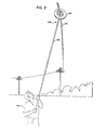
- toroidal shaped sensor and transmitter modules 20 are mounted on live power conductors 22 by use of a special, detachable hot-stick tool 108 (see Figure 2) which opens and closes a positively actuated hinging and clamping mechanism.
- Each module contains means for sensing one or more of a plurality of parameters associated with the power conductor 22 and its surrounding environment. These parameters include the temperature of the power conductor 22, the ambient air temperature near the conductor, the current flowing in the conductor, and the conductor's voltage, frequency, power factor and harmonic currents. Other parameters such as wind velocity and direction and solar thermal load could be sensed, if desired.
- each module 20 contains means for transmitting the sensed information to a local receiver 24.
- each toroidal module 20 is configured with an open, spoked area 26 surrounding the mounting hub 28 to permit free air circulation around the conductor 22 so that the conductor temperature is not disturbed.
- the power required to operate the module is collected from the power conductor by coupling its magnetic field to a transformer core encircling the line within the toroid.
- the signals produced by the various sensors are converted to their digital equivalents by the unit electronics and are transmitted to the ground receiver in periodic bursts of transmission, thus minimizing the average power required.
- One or more of these toroidal sensor units, or modules may be mounted to transmission lines within the capture range of the receiver and operated simultaneously on the same frequency channel. By slightly varying the intervals between transmissions on each module, keeping them integral numbers without a common factor and limiting the maximum number of modules in relation to these intervals, the statistical probability of interference between transmissions is controlled to an acceptable degree.
- one receiver, ground station 24, can collect data from a plurality of modules 20.
- the ground station 24 containing a receiver and its antenna 30, which processes the data received, stores the data until time to send or deliver it to another location, and provides the communication port indicated at 32 linking the system to such location.
- the processing of the data at the ground station 24 includes provisions for scaling factors, offsets, curve correction, waveform analysis and correlative and computational conversion of the data to the forms and parameters desired for transmission to the host location.
- the ground station processor is programmed to contain the specific calibration corrections required for each sensor in each module in its own system.
- the ground stations 24 are connected to the Power Control Center 54 by appropriate data transmission links 32 (radio, land lines or satellite channels) where the measured data is processed by a Dynamic State Estimator which then issues. appropriate control signals over other transmission links 33 to the switchgear 58 at electrical substations 44.
- the power supply to transmission lines may be varied in accordance with their measured temperatures and measured electrical parameters.
- transformer faults may be detected and the power supplied to the transformer controlled by the Dynamic State Estimator through switchgear.
- a Dynamic State Estimator may be located at one or more substations to control the supply of electrical power to the transformers located there or to perform other local control functions.
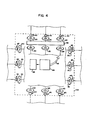
- an electrical substation 34 may be totally monitored by the electrically isolated modules 20 of the invention. Up to 15 of these modules may be connected as shown transmitting to a single receiver 24.
- the receiver may have associated therewith local control apparatus 36 for controlling the illustrative transformer bank 38 and the electrical switchgear indicated by the small squares 40.
- the modules 20 may be mounted to live conductors without the expense and inconvenience of disconnecting any circuits and require no wiring at the substation 34.
- the receiver 24 also transmits via its transmission link 32 the information received, from the modules 20 (for determining the total state of the electrical substation) to the Central Control Station 54 of the electrical delivery system.
- modules 20 are located throughout the delivery system monitoring transformer banks 40 and 42, substations 44 and 46, transmission lines generally indicated at 48 and 50, and feeder sections generally indicated at 52.
- a number of modules are preferably located along transmission lines such as lines 48 and 50, one per phase at each monitoring position. By monitoring the temperature of the conductors they indicate the instantaneous dynamic capacity of the transmission line. Since they are located at intervals along the transmission line they can be utilized to determine the nature and location of faults and thus facilitate more rapid and effective repair.
- the ground stations 24 collect the data from their local modules 20 and transmit it to the Power Control Center 54 on transmission links 33.
- the Power Control Center controls automatic switching devices 56, 58 and 60 to control the system.
- ground station 24 located at transformer bank 42 may be utilized to control the power supplied to transformer bank 42 via a motorized tap system generally indicated at 62.
- the module 20 comprises two halves of a magnetic core 64 and 66, and a power takeoff coil 68, and two spring loaded temperature probes 70 and 72 which contact the conductor and an ambient temperature probe 74.
- a spring 78 is provided, which engages the conductor 22 and remains engaged with the conductor and connects it to the case 76 before and during contact of the probes 70 and 72 with the conductor. Alternatively, or simultaneously, contact may be maintained through conductive inputs in the hub 28.
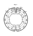
- the electrical current in the conductor is measured by a Rogowski coil 80 shown in Figure 7.
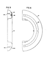
- the voltage of the conductor is measured by a pair of arcuate capacitor plates 82 in the cover portions of the donut, only one of which is shown in Figures 8 and 9.
- the electronics is contained in sealed boxes 84 within the donut 20 as shown in Figure 10.
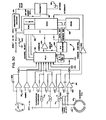
- Block diagrams of the electronics of the donut 20 are shown in Figures 28 and 30.
- the voltage sensing plates 82 are connected to one of a plurality of input amplifiers generally indicated at 86.
- the input amplifier 86 connected to the voltage sensing plates 82 measures the current between them and local ground indicated at 88, which is the electrical potential of the conductor 22 on which the donut 20 is mounted.
- the amplifier 86 provides a measure of the current flowing between the plates 82 and the earth through a capacitance C1 (see Figures 32 and 33). That is, it measures the current collected by the plates 86 which would otherwise flow to local ground. This is a direct measure of the voltage of the conductor with respect to earth.
- the temperature transducers 70, 72, and 74, and Rogowski coil 80 are each connected to one of the input amplifiers 86.
- An additional temperature transducer may be connected to one of the spare amplifiers 86 to measure the temperature of the electronics in the donut.
- the outputs of the amplifiers are multiplexed by multiplexer 90 and supplied to a digital-to-analog converter and computer generally indicated at 92, coded by encoder 94, and transmitted by transmitter 96 via antenna 98, which may be a patch antenna on the surface of the donut as illustrated in Figure 3.
- the current and voltage are sampled by the computer 92 nine times at one-ninth intervals of the current wave form; each measurement being taken in a successive cycle.
- the computer initially goes through nine cycles to adjust the one-ninth interval timing period to match the exact frequency of the current at that time, and then makes the nine measurements.
- These measurements are transmitted to the ground station 24 and another computer 334 at the ground station ( Figure 62) calculates the current, voltage, power, reactive power, power factor, and harmonics as desired; provides these to a communications board 106; and thus to a communications link 32.
- the relative transmission intervals can be chosen to be between 37/60ths and 79/60ths of a second; each transmission interval being an integral number of 60ths of a second which do not have a common factor. This form of semi-random transmission will insure 76% successful transmission with less than two seconds between successful transmissions from the same donut in the worst case.
- the hot stick mounting tool generally indicated at 108 in Figure 3 is shown in detail in Figures 25, 26, and 27. It comprises a Allen wrench portion 110 and a threaded portion 112, mounted to a universal generally indicated at 114. Universal 114 is mounted within a shell 116 which in turn is mounted to a conventional hot stick mounting coupling generally indicated at 118; and thus the hot stick 176.
- hinge pins 140 and 142 are located near the outer edge of the donut 20 and fixed pins 146 and 148 are affixed to the donut more inwardly, if the pins 146 and 148 are spread apart, the donut will open to the position shown in Figure 6 and if the pins 146 and 148 are brought together, the donut will close.
- the pins 142 and 146 and 140 and 148 are joined by respective ramp arms 150 and 152. When cable clamp 130 is separated from nut 132, the ramp arms, and thus pins 146 and 148, are spread apart by the wedge portions 154 and 156 of cable clamp 130.
- the threaded portion 112 of the hot stick tool 108 engages the threaded portion 144 of nut 132 so that the donut 20 is securely mounted to the tool 108.
- a cable 158 passes around pins 146 and 148 and is held in cable clamp 130 by cable terminating caps 160 and 162.
- the cable 158 pulls fixed pins 146 and 148 together to securely close the donut 20 and clamp it about the conductor 22.
- the threaded portion of the hot stick tool 108 disengages the threaded portion 144 of nut 132 by continued turning in the same direction.
- Tool 164 has a file 166 mounted thereon for this purpose. It may also be provided with a threaded portion 168 to engage the threaded portion 144 of nut 132 after the cable 158 has been severed.
- the preferred embodiment of the invention provides a system predominantly employing radio transmitting modules mounted to power conductors so as to reduce greatly, if not eliminate, the use of wiring to transmit measurements at an electrical substation.
- the state of a substation and the power delivery system is determined dynamically.
- thermal line ratings are determined dynamically.
- a system for monitoring and controlling the status of electrical power station equipment and in which the sensors are capable of measuring, as required, current, voltage, frequency, phase angle, the Fourier components of current and voltage from which other quantities may be calculated, the temperature of the conductor to which they are attached, or the temperature of the ambient air surrounding the conductor to which they are attached.
- the preferred state estimator module senses various power quantities including those necessary for dynamic line ratings, and can be rapidly, safely and reliably installed and removed from an energized high voltage transmission facility, up to 345KV line to line. Such installation and removal makes use of standard utility "hot stick” tools with an adaptor tailored for the module and for operation by a single lineman or robot.
- the "hot stick” mountable unit is light in weight, compact in size, can be remotely calibrated, and is toroidal in shape with a metallic housing comprising of a central hub suitable for various conductor sizes with the "hot stick” tool capable of opening and closing the toroidal housing around the conductor.
- the hub is provided with ventilating apertures and thermally insulated inserts which grip the transmission line.
- Such a module of the above character can be brought to conductor potential before delicate electric equipment contacts the conductor.
- the module maintains positive engagement with a hot stick mountable tool except when it is "snap shut" around the conductor.
- a hinge clamp is preferably used that may be opened by an alternative hot stick mounted tool in case of failure of the hinge clamp.
- the preferred system provides an electrically isolated voltage sensor for a state estimator module of the above form. Further, the system incorporates an unsynchronized single channel radio transmission system for a plurality of modules of the above form.
- the state estimator modules 20 clamp to a high-tension power conductor 22 and telemeter power parameters to a ground station 24 (Figure 1). Each module obtains its operating power from the magnetic field generated by the current flowing in the high-tension conductor 22. Each module is relatively small and shaped like a donut, with a 12 5/8" major diameter and a maximum thickness of 4 3/4". It weighs approximately 16 pounds and may be mounted in the field in a matter of minutes using a "hot stick" ( Figure 2).
- donuts 20 are used on a circuit; one for each phase. Each donut is equipped to measure line current, line to neutral voltage, frequency, phase angle, conductor temperature and ambient temperature. Digital data is transmitted by means of a 950 MHz FM radio link in a 5-10 millisecond burst. A microcomputer at the ground station 24 processes data from the 3 phase set and calculates any desired power parameter such as total circuit kilowatts, kilo-vars, and volt-amps. Individual conductor current and voltage is also available. This data may then be passed on to a central monitoring host computer (typically once a second) over a data link 32.
- a central monitoring host computer typically once a second
- One ground station 24 may receive data from as many as 15 donuts 20, all on the same RF frequency ( Figure 4). Each donut transmits with a different interval between its successive transmission bursts, ranging from approximately 0.3 seconds to 0.7 seconds. Thus, there will be occasional collisions, but on the average, greater than 70% of all transmissions will get through.
- Environmental operating conditions include an ambient air temperature range of -40°F to +100°F; driving rain, sleet, snow, and ice buildup; falling ice from conductor overhead; sun loading; and vibrations of conductors 22.
- the module weighs approximately 16 pounds. It is provided with clamping inserts for different conductor diameters which are easily removeable and replaceable. The conductor clamping does not damage the conductor, even after prolonged conductor vibration due to the use of neoprene conductor facings 170 in the inserts 186 ( Figure 13).
- the special hot stick tool 108 is inserted into the donut 20. Turning of the hot stick causes the donut to split so that it may be placed over a conductor. Turning the hot stick in the opposite direction causes the donut to ' close over a conductor and clamp onto it tightly. The tool 108 may then be removed by simply pulling it away. Reinsertion and turning will open the donut and allow it to be removed from the line.
- Conductor temperature probes 70 and 72 are spring loaded against the conductor when the donut is installed.
- the contacting tip 174 ( Figure 10) is beryllia and inhibits corrosion and yet conducts heat efficiently to the temperature transducer within. It is also a non-conductor of electricity so as not to create a low resistance path from the conductor to the electronics.
- the hub and spoke area in the center of the donut 20 and the temperature probe placement are designed with as much free space as possible so as not to affect the temperature of the conductor.
- the radio frequency transmitter power of the donut 20 is typically 100 milliwatts. However, it may be as high as 4 watts.
- the donut 20 is protected against lightning surges by MOV devices and proper grounding and shielding practice. All analog and digital circuitry is CMOS to minimize power. consumption.
- Each donut is jumper programmable for current ranges of 80-3000 amperes or 80-1500 amperes.
- Power to operate donut electronics is derived from a winding 68 on a laminated iron core 64-66 which surrounds the line conductor. This core is split to accommodate the opening of the donut when it clamps around the conductor.
- the top and bottom portions of the aluminum outer casing of the donut are partially insulated from each other so as not to form a short circuited turn. The insulation is shunted at high frequency by capacitors 176 ( Figure 10) to insure that the top and bottom portions 76 and 81 are at the same radio frequency potential.
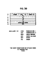
- Each message comprises the latest measured Fourier components of voltage and current and another measured condition called the auxiliary parameter, as well as an auxiliary parameter number to identify each of the five possible auxiliary parameters.
- auxiliary parameter another measured condition
- each message format is as follows:
- the auxiliary parameter rotates among 5 items on each successive transmission as follows:
- the hot stick tool 108 may be mounted on a conventional hot stick 176 so that the module 20 may be mounted on an energized conductor 22 by a man 178.
- FIG 3 it can be seen how the hot stick tool 108 provided with an Allen wrench portion 110 and a threaded portion 112 fits within a hole 122 provided in the donut 20 mounted on conductor 22.
- the donut comprises two bottom portions 76 and two covers, or top portions 81, held together by six bolts 180.
- Each bottom portion 76 is provided with a top hub 182 and a bottom hub 184 (see also Figure 13), supported on three relatively open spokes 185.
- Identical clamping inserts 186 are held within opposed hubs 182 and 184 (see Figure 13) and clamp conductor 22 with hard rubber facings 170 provided therein.
- the tops 81 ( Figure 3) are each provided with an arcuate flat flush conductor 82 insulated from the housing for measuring voltage and one of the bottom portions 76 is provided with a patch antenna 98 for transmitting data to the ground station.
- top portions 81 are each provided with a non-conductive rubber seal 188 ( Figure 7) and the area around the hinge is closed by cover plates 190, water escape vents are provided in and around the access opening 122, which due to the hot stick mounting is always at the lower portion of the donut 20 when installed on a conductor 22.
- a hinge mechanism is provided, generally indicated at 192. It comprises hinge pins 140 and 142, mounted in a top plate 136 and a bottom plate 138 (see Figure 23).
- the bottom portions 76 along with their covers 81 rotate about pins 140 and 142.
- the two halves of the donut 76-76 are drawn together to clamp the conductor by bringing fixed pins 146 and 148 together by means of cable 158. They are separated by pushing a wedge against wedge arms 150 and 152 to separate pins 146 and 148 which are affixed to the bottom portion 76-76.
- a spring 78 is provided which continuously contacts the conductor during use and contacts it before it comes in contact with the temperature probes 70 and 72, protecting them against arcing.
- a locating pin 194 and locating opening 196 are provided.
- the multi-layer power transformer cores 64 and 66 come together with their faces in abutting relationship when the unit is closed. They are spring loaded against each other and mounted for slight relative rotations so that the flat faces, such as the upper faces 198 shown in Figure 6 will fit together with a minimum air gap when the unit is closed.
- the temperature probes 70 and 72 are spring loaded so that they press against the conductor when the unit is closed.
- the ambient probe 74 is provided with a-shield 200 covering the hub area so that it looks at the temperature of the shield 200 rather than the temperature of the conductor.
- the temperature probes 70 and 72 are located in alignment with opposed spokes 185 so as to provide the least amount of wind resistance so that the conductor at the probes 70 and 72 will be cooled by the ambient air in substantially the same way as the conductor a distance away from the module 20. ,
- the ten radio frequency shunting capacitors 176 can also be seen in Figure 6, as well as the patch antenna 98.
- a Rogowski coil 80 is affixed to the covers 81 by eight brackets 202 and is connected by lead 203 to the electronics in the bottom portions 76 (Figure 10).
- the non-conductive rubber seal 188 may be seen in Figure 7, as well as recesses 206 for stainless steel fiber contacting pads 202 which contact the RF shunting capacitors 176 ( Figure 10).
- the capacitor plate 82 can be seen mounted flush with the surface of one of the covers 81. It may also be seen in Figure 9 how the openings 206-208 for the Rogowski coil are provided with slots 210 to prevent the formation of a short circuiting path around it.
- the arcuate capacitor plates 82 are insulated from the case 81 by teflon or other non-conducting material 212.
- the surface gap between the capacitor plate 82 and the surface of the case 81 is .005 inches.
- the plates 82 are mounted to the tops 81 by means of screws 214 passing through insulated bushings 216 and nuts 218, or by other comparable insulated mounting means. Connection between the capacitor plates 82 and the electronics may be made by means of the screws 214.
- a stainless steel wool pad 202 may be seen in Figure 10 connecting to the shunt capacitor 176 which may be in the form of a feed through capacitor.
- the insulating seal 188 is shown next to the shunt capacitor 176.
- the temperature probe 70 comprises an Analog Device AD-590 sensor 220 mounted against a beryllia insert 174 which contacts the conductor 22.
- the three conductors generally indicated at 222 connect the electronics to the sensor 220 through an MOV 224.
- the sensor 220 and beryllia insert 174 are mounted in a probe head 226 which in turn is mounted to a generally cylindrical carriage 227 pushed out by spring 228 to force the beryllia insert 174 against the conductor.
- a rubber boot 229 protects the interior of the probe 70.
- the probe head 226 is formed of an electrical and heat insulating material.
- the probe 72 is mounted in a cylindrical post 230 which preferably is adjustable in and out of the lower casing 76 for adjustment to engage conductors of differing diameters.
- the other conductor temperature probe 72 is identical.
- An electronics box 84 is mounted within each of the two bottom portions 76 and top portion 81.
- the boxes 84 are hermetically sealed.
- the power pickup transformer core 66 and its mating transformer core 64 ( Figure 6) in the other half of the module is pressed by leaf spring 232 against the mating core 64 and is pushed against post 234 by means of spring 236 so that the flat faces 198 of the two cores 64 and 66, shown in Figure 6, will come together in a flat face to face alignment when the module is closed.
- Opening 242 is provided for electrical wiring connecting the sealed circuit containers 84 in both halves of the device. It should be noted how opening 242 is open, again to prevent encircling the wiring.
- the opening 244 for the ambient sensor 74 and the opening 246 for the conductor sensor 70 may be seen in Figure 11.
- the hubs 182 and 184 and spokes 185 may be seen in Figures 10 and 11 although the openings 248 in the spoke 185 of Figure 10 are not shown in order that the temperature probe 70 may be shown in detail.
- FIG. 12 and 13 it can be seen how the clamping inserts 186 fit within the hubs 182 and 184 and how the f acings 170 fit within the inserts 186.
- the inserts 186 are made in sets having differing inner diameters to accommodate conductors 22 of differing diameters.
- the clamping inserts 186 are provided with alignment tabs 250 which fit into the hubs 182 and 184.
- Each of the inserts 186 is identical, one being upside down with respect to the other when installed as shown in Figure 14.
- Each is provided with a screw hole 252 for screw mounting them within hubs 182 and 184 and are provided with a raceway 254 for insertion of and to hold the hard conducting neoprene rubber facings 170, which may be of material, having a hardness of 70 durometer on the Shore A scale.
- the facings 170 are preferably filled with a conducting powder, such as graphite, to establish electrical contact with the conductor 22.
- pins 142 of the hinge is shown in Figure 18. All of the pins are provided with a non-conducting ceramic coating 256 which may be plasma sprayed thereon, so that the pins do not provide, together with the plates 136 and 138 of the hinge ( Figure 23), a shorted turn.
- an emergency hot stick mountable tool 164 can be used to open the donut 20 if for any reason the hinge clamp jams.
- This tool comprises an elongated file 166 used to cut the cable 158. After the cable 158 has been cut, a threaded portion 168 of the emergency tool may be threaded into the thread portion 144 of nut 132 (see Figure 24) to remove the opened donut 20.
- the cable clamp 130 is provided with a raised key portion 258 which guides the cable clamp's motion in a guideway opening 260 in the top plate 136.
- the circular opening 262 in the top plate 136 may be seen, in which the boss 134 of nut 132 fits to keep it from moving.
- a similar boss on the bottom of the nut 132 fits into a circular opening in bottom plate 138, as does a similar key 264 on the bottom of cable clamp 130 fit into a guiding opening in bottom plate 138.
- the plates 136 and 138 are secured together by bolts 266 and 268 and are held apart by spacers 270 and 272 ( Figures 21 and 23) about the bolts 266 and 268.
- Cover plate 136 is machined with openings 274 and ribs 276 to make it as strong and light as possible.
- Figure 21 shows the hinge clamp mechanism with the top plate 136 removed and the donut 20 closed, the cable 158 pulling pins 146 and 148 tightly together.
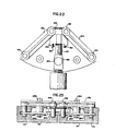
- FIG 22 the hinge clamp mechanism is shown with top plate 136 removed and the cable clamp 130 spread apart from the nut 132 by the barrel 124.
- the wedges 154 and 156 have pushed ramp arms 150 and 154 to spread apart fixed pins 146 and 148, to open the donut.
- hinge pins 140 and 142 fit into receiving portions 278 and 280 of each bottom portion 76 of the donut 20.
- fixed pins 146 and 148 fit into portions 282 which are shown partly cut away in Figure 23. Portions 282 are located closer to the central axis of the donut 20 than hinge pins 142.
- the hot stick tool 108 ( Figures 25, 26 and 27) for mounting to a conventional hot stick 176 comprises a conventional hot stick mounting coupling 118, a barrel portion 116, a universal joint 114 which accommodates misalignment of the line of the stick 120 and the receiving opening 122 (see Figure 3) in the donut 20.
- the donut engaging Allen wrench portion 110 and threaded portion 112 of the hot stick tool 108 and the sleeve 116 which holds the base 288 of the universal 114 rigidly to the mounting 290 for the hot stick tool mounted portion of the coupling 118.
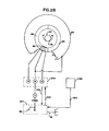
- the state estimator module electronics are shown in their overall configuration in Figure 28. They comprise a power supply 292, digitizing and transmitting electronics 294, sensors indicated by the box 296, and antenna 98.
- the center tap 9 of the power pickoff coil 68 is connected to the aluminum shell of the module 20, which in turn is connected directly to the power conductor 22 by spring 78 and by the conducting facings 170 ( Figures 12 and 13).
- the power conductor 22 becomes the local ground as shown at 88 for the electronics 294.
- the power supply supplies regulated +5 and -8 volts to the electronics 294 and an additional switched 5.75 volts for the transmitter as indicated at 300.
- the electronics 294 provides a transmitter control signal on line 302 to control the power supply to the transmitter.
- the sensors 296 provide analog signals as indicated at 304 to the electronics 294.
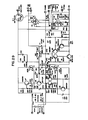
- the detailed schematic electrical circuit diagram of the power supply 292 is shown in Figure 29.
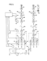
- FIG. 30 is a schematic block diagram of the electronics 294.
- the Rogowski coil 80 is connected to one of a plurality of input amplifiers 86 through current range select resistors 306.
- the voltage sensing plates 82 are connected to the uppermost amplifier which is provided with a capacitor 308 in the feedback circuit which sets gain and provides an amplifier output voltage in phase with line to neutral high tension voltage. It also provides integrator action for the measurement of current the same way as the amplifier connected to the Rogowski coil.
- amplifier 86 connected to the voltage sensing plate 82 is a low impedance current measuring means connected between the power conductor 22 (i.e., ground 88) and the plates 82.
- Each of the temperature transducers 72 and 74 is connected to a separate one of the amplifiers 86 as shown. Spare amplifiers are provided for measurement of additional characteristics such as the interior temperature of the donut 20.
- Each of the amplifiers 86 is connected for comparison with the output of digital analog converter means 310, 2.5 volt reference source 312 at comparator 314 by the multiplexer 90 under control of the digital computer 316.
- the digital computer may be a Motorola CMOS 6805 microprocessor having I/O, RAM, and timer components.
- a programmable read only memory 318 is connected thereto for storing the program.
- a zero crossing detector 320 detects the zero crossings of the current in the Rogowski coil 80 and provide basic synchronization.
- the donut ID number is selected by jumpers generally indicated at 322.
- the digitized data assembled into appropriate messages is encoded in Manchester code by the encoder 94 and supplied to a 950 megahertz transmitter 96 which then supplies it to the antenna 98.
- FIG. 31 The schematic electrical circuit diagram of the electronics 294 is shown in Figure 31, comprising Figures 31A through 31D which may be put together to form Figure 31 as shown in Figure 31E.
- the grounds therein are shown as triangles. A inside the triangle indicates an analog ground and D a digital ground. Both are connected to the common terminal as indicated in Figures 28 and 31C.
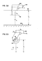
- the operation of the voltage sensor may be understood with reference to Figure 32.
- the metal plates 82 form one plate of a capacitive divider between conductor 22 and ground, comprising the equivalent capacitor Cl between ground and plate 82 and equivalent C2 between conductor 22 and the plate 82.
- the low impedance integrating operational amplifier of the invention shunts capacitance C2 and effectively eliminates it from the circuit.
- the potential of plates 82 is therefore made to be the same as that of conductor 22 through the operational amplifier 326.
- the potential between the plates 82 and ground 324 is the potential V L between the line 22 and the ground 324. Therefore, the current in the capacitance C 1 is now directly proportional to the voltage V L . Therefore, the low impedance integrater connected operational amplifier 326 will provide an AC output voltage exactly proportional to the current in the capacitance C 1 and thus directly proportional to the high voltage V L on the conductor 22.
- the width and length of the sensing plates must be made very large in comparison with the width of the gap separating them from the housing and if any protective coating is used over the sensing plate it must have no appreciable thickness. Furthermore, the outer surface of the sensing plate must conform, as closely as possible, with the outer surface of the housing 81.
- sensing plates 82 shown in Figures 8, 9, and 10 are made very long and have gaps to the housing at their ends of only .020 inches and gaps 212 along them of .005 inches in width.
- the plates 82 are approximately 3/8ths of an inch in width, which is of course very much greater than the gaps of .05 inches and .020 inches.
- the state estimator module 20 Since the state estimator module 20 is mounted in isolation on a high-tension transmission line it is desirable to derive as much information as possible from the sensors contained within it with a minimum of complexity and to transmit this raw data to the ground station 24 ( Figure 1). Calculation of various desired quantities may then be made on the ground.
- the ground station can then easily compute the quantities of interest, for example, RMS amplitude of voltage and current, their relative phase and harmonic content.
- the data transmissions take place in a five to ten second millisecond interval, which is synchronized with the zero crossing of the donut 20.
- the relative phase of three phases of a transmission line as shown in Figure 1 may be derived.
- V A and V B and I A and I B which are: where S T equals the total number of samples in the apparatus disclosed 9, S equals the sample, and V S and IS are the value of the measured voltage and current at each sample S. From these the RMS voltage V and current I may be derived by the formulas: real power is: and reactive power is:
- a single substation 34 may have as many as fifteen donuts 20 transmitting data to a single receiver 24. Since radio receivers are expensive and radio frequency channel allocations are hard to obtain, it is desirable to have all units share a single channel. For weight and economy it is desirable to minimize the equipment in the donuts 20 at the expense of complicating the receiver 24.
- Our donuts 20 are programmed to send out short burst transmissions at "random" with respect to each other, and to do so often enough that occasional interference between two or more transmissions does not destroy a significant portion of the data. This is accomplised by assigning to each donut 20 transmitting to a single receiver 24 a fixed transmission repetition interval so that no synchronization is required. The interval between transmissions of each of the donuts is an integral number and these numbers are chosen so that no two have a common factor.
- FIG. 4 A timing diagram is shown in Figure 4, where the sine wave is the current as measured by the Rogowski coil. At zero crossing labeled ⁇ timing is started. During the next cycle labled 1 and succeeding cycles through the eighth, the nine successive Fourier measurements I S and V S are made. During the ninth cycle the period of the previous eight cycles is utilized to define the sampling interval and the Fourier samples of the current and voltage are again taken during the next eight cycles. These measurements are utilized to compute V A , V B , I A and I B . At the end of the next cycle labeled 9 at the ⁇ crossings, twenty-one cycles have occurred.
- the program loads shift registers with the identification number of the donut, the auxiliary number, the Fourier components V A , V B , I A' I B' the digitized auxiliary parameters and the CRC (a check sum).
- the transmission 328 begins and takes place over a short interval of 5 to 10 milliseconds, (approximately 5 milliseconds in the apparatus disclosed). Then at the ⁇ crossing at the end of the cycle beginning at W - 1, that is after W cycles, the program is reset to ⁇ going back to the left hand side of the timing diagram of Figure 34.
- the state estimator module 20 (sometimes called herein the substation monitor) is a MC146805E2 microprocessor device.
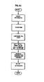
- Donut The "Donut” software specification is divided into three major sections, reflecting the three tasks performed by the software. They are:
- the background processing that performs the bulk of the "Donut” operations. Included are transmitter control, sample rate timing, analog value conversion, and general "housekeeping",
- the interrupt processing. that handles A.C. power zero-crossing interrupts and maintains the on-board clock which is used for cycle timing, and
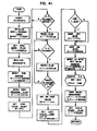
- Program modules are described via flowcharts and an accompanying narrative.
- the flowcharts use standard symbols, and within each symbol is noted the function being performed, and often a detailed logic statement.
- Subroutine calls contain the name of the subroutine, a statement of the sub-outline, a statement of its function, and the flowchart section which describes it as shown in Figure 35.
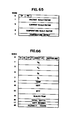
- the memory map is shown in Figure 36, the PIA Definitions in Figure 37, and the Data Transmission Format in Figure 38.
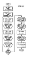
- PURPOSE MAIN is the monitor background processing loop.
- ENTRY POINT MAIN CALLING SEQUENCE: JMP MAIN (from RESET) REGISTER STATUS: A, X not preserved. TABLES USED: None.
- MAIN calls SYNC to time the AC frequency and compute the sampling rates ⁇ HKEEP to perform general initialization, and GETVAL to sample the analog values.
- COMPUT is called to finish the Fourier calculations, the watchdog timer is kicked, and CRC12 is called to calculate the CRC value for the data to be transmitted.
- SHIFT is called to load the shift register, XMIT is called to transmit the data to the ground station, the watchdog is kicked* and the entire cycle is repeated.
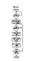
- PUPPOSE SYNC times the AC frequency and calculates the sampling interval.
- ENTRY POINT SYNC CALLING SEQUENCE: JSR SYNC Return REGISTER STATUS: A, X not preserved. TABLES USED: None.
- CALLED BY MAIN CALLS: DIV3X9 EXCEPTION CONDITIONS: None.
- SYNC initializes the zero crossing count and sets the sync mode flag.
- the sum buffer is cleared for use as a time accumulator, the zero crossing occurred flag is resets and the cycle counter is set to 10.
- the zero crossing occurred flag is monitored until 10 zero crossing interrupts have occurred, at which point the time value is moved to the sum buffer.
- DIV3X2 is called to divide the 10 cycle time by 9, the quotient is saved as the sampling time, the start flag is set, and a return is executed.
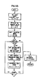
- PURPOSE HKEEP performs cycle initialization.
- ENTRY POINT HKEEP CALLING SEQUENCE: JSR HKEEP Return REGISTER STATUS: A, X not preserved.
- HKEEP releases the DAC tracking register, clears the sum buffers, and resets the tiding value remainder.
- the Donut I. D. number is read and stored in the data buffers the cycle interval time is retrieved from the TIMTBL based on the I. D. number, and the .auxilliary data I. D. number is bumped. A return is then executed.
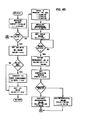
- PUEPDSE GETVAL reads the nine data samples.
- ENTRY POINT GETVAL CALLING SEQUENCE: JSR GETVAL Return REGISTER STATUS: A. X not preserved. TABLES USED: None.
- GETVAL monitors the time-to-sample flag. When set, the flag is resets SAMPLE is called to sample the analog values, and the watchdog timer is kicked. When the cycle has been repeated nine times, a return is executed.
- PURPOSE SAMPLE reads and saves the analog values.
- ENTRY POINT SAMPLE CALLING SEQUENCE: JSR SAMPLE Return REGISTER STATUS: A, X not preserved. TABLES USED: None.
- CALLED BY GETVAL CALLS: READAC, SUMS EXCEPTION CONDITIONS: None.
- SAMPLE calls READAC to read the current and voltage values and SUMS to update the Fourier sums, A return is executed unless all nine samples have been taken, in which case READAC is called to read the auxilliary data value.
- the analog value tracking register is released, and a return is executed.
- the trial valu is written to the DAC as three four-bit values, and the DAC conversion is initiated.
- a short register-decrement delay loop allows the DAC time to convert, the Incremental value is divided by two, and the comparator. input is checked. The incremental value is subtracted/added to the test value if the test value was higher/lower than the actual analog value.
- PURPOSE SUMS multiplies the analog values by the trigonometric values of the phase angles and sums the results.
- ENTRY POINT SUMS CALLING SEQUENCE: JSR SUMS Return REGISTER STATUS: A, X not preserved.
- TABLES USED COSINE - Table of cosine values .
- SUMS calls ABSVAL to move the absolute value of the analog value to the multiply buffers moves the trig value to the buffer, and calls MULT to perform the multiplication.
- ADDCOS or ADDSIN is called to add the product to the appropriate sum buffer. This cycle is repeated for the sine and cosine values for both voltage and current.
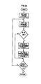
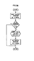
- PURPOSE COMPUT performs necessary scaling functions.
- ENTRY POI 'T COMPUT CALLING SEQUENCE: JSR COMPUT Return REGISTER STATUS: A, X not preserved. TABLES USED: None.
- CALLED BY MAIN CALLS: DIVABS, DIVAX2, DIVCNV EXCEPTION CONDITIONS: None.
- COMPUT moves the scale factor to the divide buffer, calls DIVABS to move the absolute value of the fourier sum to the buffers and calls DIV4X2 to perform the division.
- DIVCNV is called to apply the proper sign to the quotient, and the value . is moved to the data buffer. This cycle is repeated for each of the four fourier sums, and a return is executed.
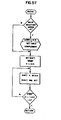
- PURPOSE CRC12 computes the CRC value.
- ENTRY POINT CRC12 CALLING SEQUENCE: JSR CRC12 Return REGISTER STATUS: A, X not preserved. TABLES USED: None.
- CALLED BY MAIN CALLS: Local Subroutine: CPOLY Figure 51 EXCEPTION CONDITIONS: None.,
- CRC12 sets a counter to the number of bytes in the data bvffer, initializes the CRC value, and gets the data buffer start address. Each 6 bit group of data is exclusively 'or'ed into the CRC value, -and CPOLY is called to "or" the resulting value with the polynomial value. When all bits have been processed, a return is executed.
- CPOLY sets a shift counter for 6 bits.
- the CRC value is shifted left one bit. If the bit shifted .out is a one, the CRC value is exclusively 'or'ed with the polynomial value.
- a return is executed.
- PURPOSE SHIFT loads the shift register with the data to be transmitted.
- ENTRY POINT SHIFT , CALLING SEQUENCE: JSR SHIFT Return REGISTER STATUS: A, X not preserved. TABLES USED: None.
- CALLED BY MAIN CALLS: Local Subroutine: SHIFTE/SHFAGN - Figure 53 EXCEPTION CONDITIONS: None.
- SHIFT calls SHIFTS4 successively to shift four bits of data at a time into the shift register, starting with the most significant bit.
- SHIFT4 and SHF AGN are called to fill the shift register with trailing seroes and a return is executed.
- SHIFT4 shifts the four data bits in A(0-3) into the hardware shift register by setting/resetting the data bit and toggling the register clock bit. When four bits have been shifted, a return is executed.
- SHFAGN is a special entry to SHIFT4 which allows the desired bit count (1-4) to be passed in X.
- PURPOSE XHIT transmits the contents of the shift register to the ground station.
- ENTRY POINT XMIT CALLING SEQUENCE: JSR XMIT Return REGISTER STATUS: A, X not preserved. TABLES USED: None.
- CALLED BY MAIN CALLS: None.
- XMIT monitors the zero-crossing count. When the count reaches the time-to-transmit count, the transmitter is enabled, and a one millisecond warmup delay is executed.
- the processor clock is initialized for external oscillator, and the clock value is set to the bit count plus shut-off delay.
- MULT performs a double precision multiplication by shifting a bit out of the multiplier, successively adding the multiplicand to the product, and shifting the product.
- the watchdog timer is kicked, and a return is executed.
- DIVABS gets the absolute value of the value at X and sets the sign flag.
- CALLED BY COMPUT CALLS: COMP2 EXCEPTION CONDITIONS: None.
- DIVABS resets the sign flag and tests the most significant bit of the value at X. If set, COMP2 is called to find the two's complement cf the four byte value, and the sign flag is set to $FF. A return is then executed.
- DIVCNV applies the sign and divides the value by sixteen.
- CALLED BY COMPUT CALLS: COMP2 EXCEPTION CONDITIONS: None.
- DIVCNV tests the sign flag, AbSIGN, If non-zero, COMP2 is called to find the two's complement of the four byte value at X. The value is then shifted right four bits, and a return is executed.
- PURPOSE COHP2 finds the two's complement value of the vblue at X.
- CALLED BY DIVABS, DIVCNV CALLS: None.
- COMP2 complements each byte of the four byte value at X, adds one to the least significant byte, and propagates the carry through 'the regaining bytes.
- Zero Crossing Interrupts Figure 59
- PURPOSE ZCINT processes zero crossing interrupts.
- ENTRY POINT ZCINT CALLING SEQUENCE: From IRO Vector Return (RTI) REGISTER STATUS: A, X are preserved. TABLES USED: None.
- CALLED BY Hardware IRQ Vector CALLS: None.
- ZCINT tests the cycle start flag. If set, the analog tracking register is frozen, the cycle start flag is resets the time-to-sample flag is set, and the clock is set to the 1-1/9 cycle time.
- start synchronize flag is set, the clock prescaler is reset, the colck is reset to maximum value, and the start synchronize flag is reset.
- the elapsed clock time is saved as the last cycle timer the zero-crossing-occurred flag is set, the zero-crossing count is bumped, and a return is executed.
- PURPOSE CLINT processes clock interrupts.
- ENTRY POINT CLINT CALLING SEQUENCE: From IRQ Vector Return (RTI) REGISTER STATUS: A, X are preserved. TABLES USED: None.
- CALLED E Y: Hardware Clock IRQ Vector CALLS: None.
- CLINT freezes the analog tracking register, resets the clock IRQ flag, and sets the time-to-sample flag.
- the cycle time remainder value is added into the time accumulator. If a carry results, the 1-1/9 cycle time is increased by one.
- the clock is reset to the cycle time, and a return is executed.
- PURPOSE RESET performs Power-on initialization.
- ENTRY POINT RESET CALLING SEQUENCE: From Harduare Reset Vector JMF MAIN REGISTER STATUS: A, X not preserved. TABLES USED: None.
- CALLED BY Haroware Reset Vector CALLS: MAIN EXCEPTION CONDITIONS: None.
- RESET inhibits interrupts, clears RAM to zeroes, and initializes the internal clock and PIA's.
- the initial time values are initialized, and the Manchester encoder and transmitter are disabled. Interrupts are realloued, and a jump to the background processing loop is executed.
- the receiver 24 at a substation 34 as shown in Figure 4 receives data from fifteen donuts.
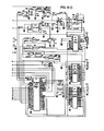
- FIG 62 there is shown an overall circuit block diagram for such a receiver 24.
- the receiver 24 can also receive analog data from up to 48 current transformers and potential transformers generally indicated at 332.
- the receiver 24 is operated by a type 68000 Central Processing Unit 334.
- the Manchester coded transmissions from the donuts 20 received by the receiver 330 are transmitted via line 336 to a communication board 106 and thence on data bus 338 to the 68000 CPU 334.
- the transformer inputs 332 are conditioned in analog board 340 comprising conditioning amplifiers, sample and hold, multiplexing and analog-to-digital conversion circuits under control of analog control board 342.
- the digitized data is supplied on data bus 338 to the CPU 334.
- the CPU 334 is provided with a random access memory 346, a programmable read only memory 348 for storing its program, and an electrically erasable read only memory 349 for storing the scaling factors and personality tables.
- the central processing unit 334 may be provided with a keyboard 350 and a 16 character single line display 352. It is also provided with an RS232 port 354 for loading and unloading so walled personality tables comprising scaling factors and the like for the donuts 20 and the transformer inputs 332.
- the receiver 24 which is sometimes called herein a remote terminal unit interface, supplies data to a remote terminal unit via current loop 356 from an RS232 communications port on communications board 106.
- the remote terminal unit may be a Moore MPS-9000-S manufactured by Moore Systems, Inc., 1730 Technology Drive, San Jose, California 95110, modified to receive and store a table of digital data each second sent on line 357.
- the MPS-900-S receives inputs from potential and current transformers, temperature sensors and the like at a substation, and converts these measurements to a digital table for transmission to a power control center 54 ( Figure 5) or for use in local substation control.
- An integral part of commercial power generation is monitoring the amount of power delivered to customers and, if necessary, purchase of power from other companies during peak demand periods. It is advantageous to the power company to be able to make measurements at remote substations, and be able to relay all the measurements to a central point for monitoring. Because of the large voltages and currents involved in commercial power distribution, direct measurement is not feasible. Instead, these values are scaled down to easily measured values through the use of Potential Transformers (PT's) for voltage, and Current Transformers (CT's) for current. Recently, we have developed another means for monitoring power line voltage and current. This is the Remote Line Monitor, a donut shaped (hence the nickname "donut”) device which clamps around the power line itself, and transmits the measured values to a radio receiver on the ground.
- PT's Potential Transformers
- CT's Current Transformers
- the Remote Terminal Interface monitors power line voltage, current, and temperature by means of Potential Transformers (PT's), Current Transformers (CT's), and temperature transducers respectively. These parameters may also be obtained from Remote Line Monitors, or "donuts" which are attached to the power lines themselves. It is the job of the RTI to receive this data, and in the case of PT's, CT's and temperature transducers, digitize and analyze the data. This data is then used to calculate desired output parameters which include voltage, current, temperature, frequency, kilowatt hours, watts, va, and vars, (the last three being measures of power). These values are then sent to the Remote Terminal Unit (RTU), and are updated once per second.
- RTU Remote Terminal Unit
- the program listings for the receiver remote terminal interface are found in Appendix B. They comprise a number of subroutines on separately numbered sets of pages. The subroutines are in alphabetical order in Appendix B. At the top of page 1 of each subroutine the name of the subroutine is given, (e.g., ACIA at the top of the first page of Appendix B).
- the routine INIT initializes the computer and begins all tasks.
- Appendix C comprises equates and macro definitions used in the system. Those headed STCEQU are for the system timing controller (an AM9513 chip). Those headed XECEQU are for the Executive program EXEC in Appendix B. Those headed RTIEQU are unique to the remote terminal interface and used throughout the programs of Appendix B.
- Analog voltages and currents will be digitized to a 12 bit bipolar value ranging from -2018 to 2047.
- Analog temperature will also be digitized to a 12 bit value which may or may not be bipolar.
- All incoming digital' data will be 12 bit values ranging from -2048 to 2047.
- the analog inputs may monitor no more than 5 separate groups.
- a group is defined as a circuit whose voltage is used for the frequency reference and power calculations
- the donvts way be !:sed to monitor a maximum of 5 additional groups.
- Analog data can come from three sources: Potential Transformers, (PT's), Current Transformers (CT's), or temperature transducers. The order of sampling will be determined by the outputs desired. (see Date Output) For voltage and curtent r 9 equally spaced samples must be taken over the space of a power line voltage cycle for the purposes of data analysis. (see Data Processing). For each voltage group (maximum of 5), a timer must be maintained to provide proper sampling intervals. This timer will be checked each sampling period and adjusted if necessary The first phase of the voltage sampled will be used as the reference for checking the sampling period timer.
- the input task knows it may begin sampling for a given group of inputs (cluster) when all of the input buffers connected with it are ready for input.
- the necessary data is collected from the A/D converterv and stored in the appropriate input buffer.
- the buffer is marked as unavailable for further input, and rade available for Fourier analysis.
- the sampling timer is then adjusted if necessary, and the input task then proceeds to the next group of buffers in the Inpvt Sequence Table.
- Input from the 'donuts' is alreadv digitized and analvzed. It is only necessary to apply a scaling factor (unique for each parsmater from each donut) to the data, and convert it to 2's comp-plement form. After this has been done, the data is in a suitable form to calculate output data..
- Donut input is not solicited* but rather is transmitted in a con-tinous stream to the RTI.
- Nhen data is received from a donut, the processor is interrupted. The incoming data is then collected in a local buffer until a full message from a donut is received and validated. If the data is not valid, the transmission is ignored, and normal processing continues. If the buffer has alreadv received valid input data for this sampling period, the transmission is ignored. Otherwise, the new data is moved from the receive buffer into the appropriate date ouffer, the age count is cleared, is marked as uaiting to be processed, end is made available for effective valve calculations.
- a Cvclical Redundancy Checl. (CRC) word vill be provided at the end of each donut transaission. If the CRC fails, the last good data transmitted tw that particular donut will be reused. If the cutput test references the buffer before new data comes in, the old date will be reused. If a donut should fail more than N (to be defined) conseoutive times, that donut will be considered to be bad, and its data will be reset to zero.
- Analog date must be subjected to Fourier transformation to e::tract the sine and cosine components of the voltage and current prior to calculating output values.
- the sine and cosine components must be scaled by a factor between 5 and 20. This scaling factor is found in the Input Personality Table, and is unique to each input.
- the effective value and the Fourier components must be scaled by one of four factors ranging between. .6 and 2.0. The scale factor used is dependent on the raw value of the effective current (Ieff). Each current input has a unique set of four factors. These may also be found in the Input Personality Table.
- the buffer is an analog input buffer
- the 9 samples are analvzed, yielding the sine and cosine components of the fundamental.
- the effective value of the waveform is then computed and stored in the buffer. The buffer is then marked as being ready for more raw data.
- the buffer is a digital (donut) buffer, then only the effective voltage and current are computed and stored in the buffer. When these calculstions are complete, the buffer is marked as being ready for more raw data.
- the output values may be calculated. Parameters thet may be calculated are: voltage, current, kilowatt hours, watts, va, and vars. Also, temperature, and frequency may be output. (These are measured, not calculated parameters.)
- Output data will be transmitted to the host in serial fashion. Data to be transmitted to the host will be stored in a circuler FIFD buffer to be emptied by the transmission routine which will be interropt driven. All d F ta must be converted to offset binary and formetted before transmission. A new set of output data will be transmitted to the host once Per second.
- the output task When a buffer is ready to be output, the wattage must be calculated (If it hasn't been already) and stored in the buffer corresponding to the phase 1 of the current involved in the calculation. When the wattage is calculated, the kilowatt hour value is updated also. After calculating Power and updating KWH, the output task will calculate the requested output parameter and output it (if the appropriate buffers to perform the calculation are ready). The output task will then proceed to the next entry in the Output Personality Table. When the end of the table is reached, all buffers, both analog and digital, are marked as ready for analysis. In addition, the output tesk will enable the transmission of the block of data Just calculated. and wait until the start of the next one second interval before starting at the top of the table again.
- the parameter will be calculated uosing the Breaker-and-a-half method. (see glossary)
- the RTI will be supplied with an integral 16 Yey keypad, and single line (16 column) display. From this kevboerd, the ' . ' set mav:
- the RTI will have the capability to upload/download any EEFROK based table through the auxiliary port upon request from the host. All programming of the RTI (configuration and sealing factor entry) uill be Performed throuph this link. Communications protocols will be defined in the design spec.
- Host interface monitor (ecv HALF OF ACIG 1)
- VARS (Va ⁇ Ib) - (Vb ⁇ Ia) (per phase) Total VAFS caloulated as per total watts above.
- This table is EEPROM based, and binds a specific input number to an input type (voltape, current, temperature), group 1, phase ir and set of correction factors.
- This table is of a fixed size and may have no more than 18 entries. Unused entries will have a value of 0. The values in this table will'be determined at installation time.
- the Output Personality Table is an EEPROM based table which defines each of the parameters to be outputs and which Parameters are necessary to calculate them.
- the number of entries (up to 61) in the table is unique to the site, and is determined at installation time.
- the entries are arranged in the order in which they are to be output. There may be no more than 61 entries in this table.
- both voltage and current readings from the selected donut(s) will be used for power (volt-amp) calculations. (ie. using voltage from a donut and current from a CT will not be permitted)
- Donuts shall have ID's ranging from 1 to 15. Each installation using donuts must start the donut ID's from 1.
- Donuts must be used in groups of three. (Their output is suitable only for use in the 3 wattmeter method.) The ID's of the donuts must be consecutive, the lowest numbered one being assumed to be Phase one, and the highest numbered one will be assumed to be phase 3.
- the Input Sequence Table is RAM based, and built at RTU startup timer based on the Output and Input Personality tables. For each group, this table specifies which inputs must be sampled simultaneously to calculate the desired outputs. The groups are entered into the table in order of their first reference in the Output Personality Table. The Input Personality Table is then referenced to find the input numbers of all phases of a given input type (ie. current) for snv group. Escis group is terminated bv a zero word. The table is terminated by a word set to all ones.
- This table is EEPROM based and contains the donut's group number-and scaling factors to be applied to donut inputs. Scale factors are unioue to each parameter input from each donut.
- the temp-perature input may also have an offset from -1021 to 1023 added to it. This offset is added after the scaling factor has been E pplied.
- the entries are arranged in order of donut ID's.
- a state diagram for the program of the central processing unit 334 of Figure 62 of the receiver 24 is shown in Figure 64. Processing tasks are indicated by the six-sided blocks. Tables stored in the electrically erasable read only memory 349 are indicated by the elongated oval boxes. Data paths are shown by dotted lines and peripheral interfaces are indicated by zig-zag lines. The transformer inputs 332 and donut input 336 are shown in the upper left. The RS232 port 354 is shown in the lower right and the output RS232 port 32 is indicated in the middle of the diagram.
- the donut scale factor table is shown in Figure 65. Since donuts are normally operated in groups of three for three-phased power measurement, word ⁇ comprises the group number of the donut (GP), followed by the phase number of the donut (PH). The following words are the voltage scale factor, current scale factor, temperature scale factors, and temperature offset respectively. Temperature offset is an 11 bit value, sign extended to 16 bits. All two word values are a floating point. There is, of course, a separate scale factor table for each of the fifteen donuts provided for. The donut scale factor tables are stored in the electrically erasable read only memory 349.
- Figure 66 is a table of the digital input buffers. There are sixteen required, one to store the received value of each of the fifteen donuts and one to act as a receiver buffer for the serial port of the communication board 106.
- Word ⁇ comprises, in addition to the donut ID and a number called buffer age, indicating how long since the information in the buffer has been updated; the following flags:
- All single word values are 12 bits, sign extended to 16 bits. All double word values are floating point. Buffer age is the number of times this data has been used.
- the first buffer (buffer ⁇ ) is used to assemble incoming donut data. Words 14-16 are defined for ⁇ 1 donuts only. Word ⁇ in the buffer number ⁇ is used for the donut status map.
- the digital input buffers are stored in the read only memory 346.
- Figure 67 is the input personality table of which there are 48 corresponding to the 48 potential transformer and current transformer inputs.
- IT identifies the input type which may be voltage, current, or temperature.
- Link is the input number of the next phase of this group of donuts. It is -1 if there are no other donuts in the group.
- Correction factor number 1 is used for correcting voltage values.
- Each of the four correction factors corresponds to a range of input values from the current transformers.
- the group number identifies groups of transformers associated with a single power line and PH identifies the phase number of the particular transformer.
- VG identifies the voltage group that the current is to be associated (that is, sampled) with. It is used, of course, only when the table is used to store values from a current transformer.
- the input personality tables are stored in the electrically erasable read only memory 349.
- 48 analog input buffers are provided to store measurements received from the 48 current potential transformers.
- the form of each of these buffers is shown in Figure 68.
- transmissions are received randomly from the donuts 20, transmitted in Manchester code to the serial port to the communications board 106.
- the checked sum (CRC) is calculated and if it agrees with the check sum (CRC) received, an interrupt is provided to the central processing unit 334, which then transfers the data to data bus 338.
- the central processing unit 68000 applies the scale factors and temperature offset to the received values, and calcu- lates the Temperature, effective Voltage (V EFF ) ' effective Current (I EFF ) ' Scaled Temperature, Total Watts, Watt Seconds and Kilowatt hours from the received data and stores the data in the appropriate Digital Input Buffer in random access memory 346.
- each of the 48 transformer inputs is sampled in turn. After its condition has been converted to digital form, an interrupt is generated, and the data is supplied to data bus 338.
- the analog board 340 causes the inputs from the potential and current transformers 332 to be Fourier sampled nine times just as current and voltage are sampled in the donuts (see Figure 34).
- the data supplied to the data bus 338 from the analog board 340 comprises 9 successive values over nine alternating current cycles. After all nine have been stored in the random access memory 346, and the appropriate correction factors ( Figure 67) applied, the fundamental sine and cosine Fourier components are calculated just as in the donuts 20.
- the appropriate donut scale factors ( Figure 65) are loaded through RS232 port 354 into the electrical erasable read only memory 349, and these are used to modify the values received from the donuts 20 before they are recorded in the digital input buffers of the random access memory 346.
- an input personality table ( Figure 67) is stored in the electrical erasable read only memory 349 corresponding to each of the current and potential transformers and this is utilized to apply the appropriate corrections to the data received by the analog board 340 before it is recorded in the analog input buffers of the random access memory 346.
- the scaled data stored in the digital input buffers and the corrected data stored in the analog input buffers is then assembled into a frame or message containing all of the defined data from all of the donuts 20 and all of the transformers 332 and transmitted via transmission link 32 to a receiver which may be the remote terminal interface of the prior art as previously described.
- the form of the analog-to-digital, multiplexed input sample and hold circuitry and program in the receiver 24 may be essentially the same as that in the donut. The same is true for the Fourier component calculation program and the calculation of the check sum (CRC).
- the programs are appropriately modified to run in the 68000 central processing unit with its associated memories.
- harmonic data is desired, then higher Fourier harmonics are calculated in the donuts 20 and transmitted to the receiver 24.
- the receiver uses the higher harmonic values to calculate the amplitude of each harmonic it is desired to measure.
- the frequency at any donut 20 may be determined, if desired, by measuring the time between transmissions received from the donut as these are an integral multiple (W, see Figure 34) of the line frequency at the donut.
- the donut may employ an accurate quartz clock to measure the time between zero crossings ( Figure 34) and transmit this frequency measurement to the receiver.
- power factor may be calculated from the Fourier components and stored in the input buffers ( Figures 66 and 68).
- Reactive power may be calculated from the Fourier components rather than real power (Watts) as selected by an additional flag in each of the Donut Scale Factor Tables ( Figure 65) and the Input Personality Table ( Figure 67).
- all of these calculations and others, as well as other information such as frequency may be stored in expanded Input Buffers ( Figures 66 and 68).
- the electrical erasable read only memory 349 may be unloaded through the RS232 port 354 when desired to check the values stored therein. They may also be displayed in the display 352 and entered or changed by means of the keyboard 350.
- the output from the receiver 24 is a frame of 64 (for example) data values from the Input Buffers ( Figures 66 and 68) chosen by an output Personality Table (not shown) stored in the electrically erasable read only memory 349. This frame of values is transmitted to the Moore remote terminal unit once each second.
- the output personality table may be displayed on display 352 and entered by keyboard 350 or entered on read out through RS232 port 354.
- a module is capable of measuring the temperature of the power line, the ambient temperature, the voltage and current of the line; the frequency and harmonic content of the line; and transmits this information to a receiver where power information such as real and reactive power and power factor may be calculated.
- a state estimator module which may be installed to all of the live power lines leading to and from a substation and to both sides of power transformers in the substation, and thus provide the totality of information required for complete remote control of the power station from a power centre, and also provide for local control.
- Our estimator modules may be installed on live monitored circuits in an existing substation having current and voltage transformers and our receiver used to collect this totality of information and transmit it to a remote terminal unit and thence to a power system control centre.
- the metallic toroidal housing for the module (which is a high frequency but not a low frequency shunt about its contents); the supporting hub and spoke means; spring loaded temperature sensors; novel voltage measuring means; transmission of Fourier components; random burst transmission on a single radio channel with the timing between bursts being artfully chosen to minimize simultaneous transmissions from two or more donuts; novel hinge clamp which may be operated by a novel hot stick mounted tool facilitating the mounting of the module to a energized power conductor; and the concept that such hot stick mounted modules when distributed throughout a power delivery system, can provide for total automatic dynamic state estimator control.
Abstract
Description
- This invention relates to apparatus for measuring the potential of a transmission line conductor, primarily a conductor in a bulk electrical power delivery system. More particularly it relates to transmission-line-mounted radio transmitting electrically isolated apparatus.
- Various power line monitoring sensors have been disclosed in the prior art. For example, see United States Patent Nos. 3,428,896, 3,633,191, 3,983,477, 4,268,818. It has been proposed to use sensors of this type for dynamic line rating of electrical power transmission lines. See for example, papers numbered 82 SM 377-0 and 83 SM 378-8 entitled DYNAMIC THERMAL LINE RATINGS, PART I, DYNAMIC AMPACITY RATING ALGORITHM: and, DYNAMIC THERMAL LINE RATINGS, PART II, CONDUCTOR TEMPERATURE SENSOR AND LABORATORY FIELD TEST EVALUATION; papers presented at the International Association of Electrical and Electronic Engineers P.E.S. 1982 summer meeting. These papers are incorporated herein by reference. However, the full potential of this new technology has not been realised. Further sensors of the type shown in the above prior art are disclosed, albeit in a much improved form, in U.S. Patent No. 4,384,229, the contents of which are incorporated in this specification by reference.
- Today, for control and protection, power supply to and from an electrical substation over various transmission lines is monitored by separate devices (current transformers, potential transformers and reactive power transducers) for measuring electrical potential, power factor and current in the conductors of the transmission line and the conductors connected to substation power transformers. These measurements are transmitted in analog fashion by various wires to a central console at the substation where their values may or may not be digitized and sent to a central station for control of the entire power system. The wiring of these devices is difficult and expensive, and every excess wire in a substation presents an additional electrical shock hazard or an induction point for electromagnetic interference on protection/telemetry circuits. Furthermore, when a failure occurs, these sensor lines may be abruptly raised to higher voltages, thus increasing the possibility of shock and failure in the measurement system.
- The high cost of capital, uncertain utility load growth trends, coupled with increasing constraints in acquiring and licensing new facilities including right-of-way for transmission lines make greater use of existing power delivery facilities (remote generating stations, the EHV bulk power network, subtransmission and distribution facilities) a paramount consideration. With deferrals that have occurred in new generation and power transmission facilities, all elements of the power system will be strained to a greater degree than in the past. In order to maintain current reliability levels under these conditions, additional real-time monitoring will be required to assist the dispatch operator and other bulk network functions conducted through a modern Power Control Centre.
- Some of the functions in a hierarchical modern Power Control Centre, operating through Regional Control Centres down to the distribution level, that require a real-time Supervisory Control and Data Acquisition System are as follows:-
- 1. State Estimation
- 2. On-Line Load Flow Detection
- 3. Optimum Power Flow Control for Real and Reactive Power Dispatch
- 4. Security (i.e. Stability) Constrained Economic Dispatch
- 5. Contingency Analysis
- 6. Automatic Generation Control and Minimum Area Control Error
- 7. Dynamic System Security Analysis
- 8. Energy Interchange Billing
- 9. System Restoration After an Emergency
- 10. Load Shedding and Generation Redispatch
- 11. Determination of Effects of Voltage Reduction and Real and Reactive Power
- 12. Synchronization of System Load Profiles to validate various computer models and to provide snap shots of maximum, minimum loads, peak day real and reactive powers on lines and equipment
- 13. Maintain Power Delivery Quality Including Harmonic Content for Critical Loads and Power Factor
- 14. Limit checking of voltage, line thermal loadings and rate of change under contingency conditions
- 15. Protective Relaying.
- The key parameters that require measurement for a modern Power Control Centre State Estimator and On-Line Load Flow that provide the input data base for the various functions listed above are:
- Line and Transformer Bank or Bus Power (MW) Flows Line and Transformer Bank or Bus Reactive Power (MVAR) Flow
- Branch Currents (I), Bus Voltage and Phase Angles Bus MW and MVAR Injections
- Energy (MWh) and Reactive Energy (MVAR-h) Circuit Breaker Status
- Manual Switch Positions
- Tap Changer Positions
- Frequency (f)
- Protective Relaying (Differential Currents, etc.) Operation
- Power Line Dynamic Ratings Based on Conductor Thermal (Temperature) Limits or Sag
- Ambient Temperature/Wind Speed
- Line and Equipment Power Factors
- Sequence-of-Events Monitoring
- One of the major problems in implementing a modern Power Control System is to add instrumentation throughout the bulk transmission network at Extra High Voltage (up to 765 kV) line voltages and at distribution substations and feeders. This must be done without disrupting existing operations of equipment and facilities that are largely in place.
- According to one aspect of the present invention there is provided means for measuring the potential of a high voltage power conductor comprising:- (A) a metallic case adjacent to the conductor and in electrical contact therewith; (B) at least one metallic plate located in the surface of said metallic case; and (C) insulating material separating said plate from said case, the separation between them along the surface of said case being very much smaller than the size of said plate.
- According to a second aspect of the invention, an electrical power line state estimator module comprises (A) a generally toroidal shaped housing mounted about the conductor, and (B) a potential sensor comprising (a) a capacitor plate mounted to the outer surface of said housing, and (b) low impedance current measuring means connected between the conductor and said capacitor plate.
- In the case of a power delivery network including a plurality of power conductors connected on the primary and secondary side of a power transformer, sensor modules may be attached on both sides of the transformer, whereby the state of the transformer may be determined. Where the network has a plurality of substations, including power transformers, a plurality of sensor modules may be provided at one substation on the primary and the secondary side of the relevant power transformer, and, likewise, sensor modules may be provided on both sides of such a transformer at another substation coupled to the first substation by a transmission line. Both substations have associated therewith respective radio receivers and state determining apparatus for determining the state of the respective transformers, with the substation state determining apparatus being connected via communications link to a central station having system state determining apparatus. Control apparatus coupled to the system state determining apparatus is provided for controlling the network in accordance with the state of the network as determined by the system state determining apparatus.
- In preferred embodiments of the system of the invention, the number of modules or transducers is limited to avoid altering the burden on existing current transformers and degrading accuracy of existing metering or relaying instrumentation. In a preferred embodiment, the modules comprise toroidal conductor State Estimator Modules associated with a ground station processor, and a receiver/transmitter. These units can be so arranged to eliminate the necessity for the multiple wiring of transducers required with conventional current and potential transformers and collect all the data required from lines and station buses with a compact system. Use of the system as described in the present specification can result in significant investment, installation labour and time savings. It completely eliminates the need for multiple transducers, hard-wiring to current transformers and potential transformers and any degrading effects on existing relaying or metering links. The system can be retrofitted on existing lines or stations or new installations with equal ease and measures:
- Line Voltage
- Power Factor or Phase Angle
- Power Per Phase
- Line Current
- Reactive Power Per Phase
- Conductor Temperature
- Ambient Temperature
- Wind Speed
- Harmonic Currents
- Frequency
- MW-h and MVAR-h (processed quantities)
- Profiles of above quantities from stored values
- The state-estimator data collection system described in this application enables power utilities to implement modern power control systems more rapidly, at lower cost and with considerable flexibility, since the devices can be moved around using hot-sticks without having to interrupt power flow. The devices can be calibrated and checked through the radio link and the digital output can be multiplexed with other station data to a central processor via remote communication link.
- In its preferred form the state estimator module includes a positive acting mechanism for hinging the two parts of the module and securely clamping and unclamping them about a live conductor while supported by a hot stick. The module allows measurement of the voltage of the conductor in a self-contained electrically isolated assembly which is small and light and uses a single radio channel in common with other modules so that up to fifteen may- be used at a single substation.
- Such hot stick activated hinge and clamp mechanisms do not exist in the prior art. The voltage transformers and capacitive dividers of the prior art are not electrically isolated. Separate measurements of all electrical quantities desired would require too much apparatus in the module. Synchronization of module transmissios would require a radio receiver in each module.
- The main features of the preferred system are as follows.
- Referring to Figure 1, toroidal shaped sensor and
transmitter modules 20 are mounted onlive power conductors 22 by use of a special, detachable hot-stick tool 108 (see Figure 2) which opens and closes a positively actuated hinging and clamping mechanism. Each module contains means for sensing one or more of a plurality of parameters associated with thepower conductor 22 and its surrounding environment. These parameters include the temperature of thepower conductor 22, the ambient air temperature near the conductor, the current flowing in the conductor, and the conductor's voltage, frequency, power factor and harmonic currents. Other parameters such as wind velocity and direction and solar thermal load could be sensed, if desired. In addition, eachmodule 20 contains means for transmitting the sensed information to alocal receiver 24. - Referring to Figure 3, each
toroidal module 20 is configured with an open,spoked area 26 surrounding the mountinghub 28 to permit free air circulation around theconductor 22 so that the conductor temperature is not disturbed. The power required to operate the module is collected from the power conductor by coupling its magnetic field to a transformer core encircling the line within the toroid. The signals produced by the various sensors are converted to their digital equivalents by the unit electronics and are transmitted to the ground receiver in periodic bursts of transmission, thus minimizing the average power required. - One or more of these toroidal sensor units, or modules, may be mounted to transmission lines within the capture range of the receiver and operated simultaneously on the same frequency channel. By slightly varying the intervals between transmissions on each module, keeping them integral numbers without a common factor and limiting the maximum number of modules in relation to these intervals, the statistical probability of interference between transmissions is controlled to an acceptable degree. Thus, one receiver,
ground station 24, can collect data from a plurality ofmodules 20. - The
ground station 24, containing a receiver and itsantenna 30, which processes the data received, stores the data until time to send or deliver it to another location, and provides the communication port indicated at 32 linking the system to such location. The processing of the data at theground station 24 includes provisions for scaling factors, offsets, curve correction, waveform analysis and correlative and computational conversion of the data to the forms and parameters desired for transmission to the host location. The ground station processor is programmed to contain the specific calibration corrections required for each sensor in each module in its own system. - Referring to Figure 5, the
ground stations 24 are connected to the Power Control Center 54 by appropriate data transmission links 32 (radio, land lines or satellite channels) where the measured data is processed by a Dynamic State Estimator which then issues. appropriate control signals overother transmission links 33 to the switchgear 58 at electrical substations 44. Thus the power supply to transmission lines may be varied in accordance with their measured temperatures and measured electrical parameters. Similarly, when sensors are located in both the primary and secondary circuits of power transformers, transformer faults may be detected and the power supplied to the transformer controlled by the Dynamic State Estimator through switchgear. - A Dynamic State Estimator may be located at one or more substations to control the supply of electrical power to the transformers located there or to perform other local control functions.
- Thus, as shown in Figure 4, an
electrical substation 34 may be totally monitored by the electricallyisolated modules 20 of the invention. Up to 15 of these modules may be connected as shown transmitting to asingle receiver 24. The receiver may have associated therewith local control apparatus 36 for controlling theillustrative transformer bank 38 and the electrical switchgear indicated by thesmall squares 40. Themodules 20 may be mounted to live conductors without the expense and inconvenience of disconnecting any circuits and require no wiring at thesubstation 34. Thereceiver 24 also transmits via itstransmission link 32 the information received, from the modules 20 (for determining the total state of the electrical substation) to the Central Control Station 54 of the electrical delivery system. - The system is adapted for total monitoring and control of a bulk electrical power delivery system as illustrated in Figure 5. Here,
modules 20 are located throughout the delivery system monitoringtransformer banks - A number of modules are preferably located along transmission lines such as
lines 48 and 50, one per phase at each monitoring position. By monitoring the temperature of the conductors they indicate the instantaneous dynamic capacity of the transmission line. Since they are located at intervals along the transmission line they can be utilized to determine the nature and location of faults and thus facilitate more rapid and effective repair. - The
ground stations 24 collect the data from theirlocal modules 20 and transmit it to the Power Control Center 54 ontransmission links 33. The Power Control Center, in turn, controlsautomatic switching devices - As illustrated in Figure 5,
ground station 24 located attransformer bank 42 may be utilized to control the power supplied totransformer bank 42 via a motorized tap system generally indicated at 62. - As shown in Figure 6, the
module 20
comprises two halves of amagnetic core power takeoff coil 68, and two spring loaded temperature probes 70 and 72 which contact the conductor and anambient temperature probe 74. - In order to insure that the
case 76 is precisely at the potential of theconductor 22 when the conductors are contacted by theprobes 70 and 72, aspring 78 is provided, which engages theconductor 22 and remains engaged with the conductor and connects it to thecase 76 before and during contact of theprobes 70 and 72 with the conductor. Alternatively, or simultaneously, contact may be maintained through conductive inputs in thehub 28. - The electrical current in the conductor is measured by a
Rogowski coil 80 shown in Figure 7. - The voltage of the conductor is measured by a pair of
arcuate capacitor plates 82 in the cover portions of the donut, only one of which is shown in Figures 8 and 9. The electronics is contained in sealedboxes 84 within thedonut 20 as shown in Figure 10. - Block diagrams of the electronics of the
donut 20 are shown in Figures 28 and 30. - Referring to Figure 30, the
voltage sensing plates 82 are connected to one of a plurality of input amplifiers generally indicated at 86. Theinput amplifier 86 connected to thevoltage sensing plates 82 measures the current between them and local ground indicated at 88, which is the electrical potential of theconductor 22 on which thedonut 20 is mounted. Thus theamplifier 86 provides a measure of the current flowing between theplates 82 and the earth through a capacitance C1 (see Figures 32 and 33). That is, it measures the current collected by theplates 86 which would otherwise flow to local ground. This is a direct measure of the voltage of the conductor with respect to earth. - As also shown in Figure 30, the
temperature transducers Rogowski coil 80 are each connected to one of theinput amplifiers 86. An additional temperature transducer may be connected to one of thespare amplifiers 86 to measure the temperature of the electronics in the donut. The outputs of the amplifiers are multiplexed bymultiplexer 90 and supplied to a digital-to-analog converter and computer generally indicated at 92, coded by encoder 94, and transmitted by transmitter 96 viaantenna 98, which may be a patch antenna on the surface of the donut as illustrated in Figure 3. - As illustrated in the timing diagram of Figure 34, the current and voltage are sampled by the
computer 92 nine times at one-ninth intervals of the current wave form; each measurement being taken in a successive cycle. The computer initially goes through nine cycles to adjust the one-ninth interval timing period to match the exact frequency of the current at that time, and then makes the nine measurements. These measurements are transmitted to theground station 24 and anothercomputer 334 at the ground station (Figure 62) calculates the current, voltage, power, reactive power, power factor, and harmonics as desired; provides these to acommunications board 106; and thus to acommunications link 32. - For a maximum of fifteen donuts for which it is desired to transmit information each second or two, the relative transmission intervals can be chosen to be between 37/60ths and 79/60ths of a second; each transmission interval being an integral number of 60ths of a second which do not have a common factor. This form of semi-random transmission will insure 76% successful transmission with less than two seconds between successful transmissions from the same donut in the worst case.
- The hot stick mounting tool generally
indicated at 108 in Figure 3 is shown in detail in Figures 25, 26, and 27. It comprises aAllen wrench portion 110 and a threadedportion 112, mounted to a universal generally indicated at 114.Universal 114 is mounted within ashell 116 which in turn is mounted to a conventional hot stick mounting coupling generally indicated at 118; and thus thehot stick 176. - When the
hot stick tool 108, as shown in Figure 3, is inserted into theopening 122 in thedonut 20, the Allen wrench portion engages barrel 124 (Figure 24) which is oppositely threaded on each of itsends portion 126 is engaged with a mating threaded portion of acable clamp 130 and threadedportion 128 engages a mating threadedportion 144 of anut 132. Thenut 132 is fixed by means ofbosses 134 inplates pins 140 and 142 (Figure 23). Thus, when thehot stick tool 108 is inserted, andbarrel 124 rotated in one direction,cable clamp 130 is brought towardsnut 132, while whenbarrel 124 is rotated in the other direction,cable clamp 130 moves away fromnut 132. Threadedportion 144 ofnut 132 engages the threadedportion 112 of thehot stick tool 108, such that whencable clamp 130 andnut 132 are spread apart the threadedportion 112 of the hot stick tool is threaded intonut 132 so that thedonut module 20 may be supported on thetool 108. - Since hinge pins 140 and 142 are located near the outer edge of the
donut 20 and fixedpins pins pins pins respective ramp arms cable clamp 130 is separated fromnut 132, the ramp arms, and thus pins 146 and 148, are spread apart by thewedge portions cable clamp 130. At the same time the threadedportion 112 of thehot stick tool 108 engages the threadedportion 144 ofnut 132 so that thedonut 20 is securely mounted to thetool 108. Acable 158 passes aroundpins cable clamp 130 bycable terminating caps cable clamp 130 andnut 132 are brought together, thecable 158 pulls fixedpins donut 20 and clamp it about theconductor 22. Shortly after it is drawn tight, the threaded portion of thehot stick tool 108 disengages the threadedportion 144 ofnut 132 by continued turning in the same direction. - If for any reason the
donut 20 cannot be removed from aconductor 22 by using thehot stick tool 108, another hot stick tool generally indicated at 164 in Figure 20 may be used to cut thecable 158.Tool 164 has afile 166 mounted thereon for this purpose. It may also be provided with a threadedportion 168 to engage the threadedportion 144 ofnut 132 after thecable 158 has been severed. - The preferred embodiment of the invention provides a system predominantly employing radio transmitting modules mounted to power conductors so as to reduce greatly, if not eliminate, the use of wiring to transmit measurements at an electrical substation. The state of a substation and the power delivery system is determined dynamically. In addition thermal line ratings are determined dynamically. Also provided is a system for monitoring and controlling the status of electrical power station equipment, and in which the sensors are capable of measuring, as required, current, voltage, frequency, phase angle, the Fourier components of current and voltage from which other quantities may be calculated, the temperature of the conductor to which they are attached, or the temperature of the ambient air surrounding the conductor to which they are attached.
- The preferred state estimator module senses various power quantities including those necessary for dynamic line ratings, and can be rapidly, safely and reliably installed and removed from an energized high voltage transmission facility, up to 345KV line to line. Such installation and removal makes use of standard utility "hot stick" tools with an adaptor tailored for the module and for operation by a single lineman or robot. The "hot stick" mountable unit is light in weight, compact in size, can be remotely calibrated, and is toroidal in shape with a metallic housing comprising of a central hub suitable for various conductor sizes with the "hot stick" tool capable of opening and closing the toroidal housing around the conductor. The hub is provided with ventilating apertures and thermally insulated inserts which grip the transmission line. Such a module of the above character can be brought to conductor potential before delicate electric equipment contacts the conductor. The module maintains positive engagement with a hot stick mountable tool except when it is "snap shut" around the conductor. A hinge clamp is preferably used that may be opened by an alternative hot stick mounted tool in case of failure of the hinge clamp.
- The preferred system provides an electrically isolated voltage sensor for a state estimator module of the above form. Further, the system incorporates an unsynchronized single channel radio transmission system for a plurality of modules of the above form.
- The invention will now be described by way of example with reference to the drawings in which:-
- Figure 1 is a perspective view of a state estimator module installed on an electrical transmission line;
- Figure 2 is a perspective view showing how the state estimator module may be hot stick mounted to a live conductor;
- Figure 3 is a perspective view of the state estimator module mounted to a conductor;
- Figure 4 is a diagrammatic view of a substation;
- Figure 5 is a diagrammatic schematic view of a monitored and controlled power delivery system in accordance with the invention;
- Figure 6 is a top view of a state estimator module with its covers thereof removed;
- Figure 7 is a bottom view of the covers of the state estimator module;
- Figure 8 is a top view of one of the covers;
- Figure 9 is a side view of one of the covers, partly in cross section;
- Figure 10 is an enlarged cross sectional view taken along the line 10-10 of Figure 6 with the cover in place;
- Figure 11 is an enlarged cross sectional view taken along the line 11-11 of Figure 6 with the cover in place;
- Figure 12 is an enlarged fragmentary view of the hub portion of the state estimator module of Figure 6;
- Figure 13 is a cross sectional view taken along the line 13-13 of Figure 12;
- Figure 14 is an enlarged view of the conductor clamping jaws shown in Figure 12;
- Figure 15 is a cross section taken along the line 15-15 of Figure 14;
- Figure 16 is a side view showing the inside of one of the jaws shown in Figure 14;
- Figure 17 is a enlarged perspective view of one of the jaws of Figure 14;
- Figure 18 is a view of one of the pins of a hinge clamp mechanism ;
- Figure 19 is a cross sectional view thereof taken along the line 19-19 of Figure 18;
- Figure 20 is a fragmented partially diagrammatic top view of the hinge clamp and the tool utilized to open it if it jams;
- Figure 21 is a top view similar to Figure 20 showing the hinge clamp mechanism when the state estimator module is clamped about a conductor;
- Figure 22 is a view similar to Figure 21 showing the hinge clamp mechanism when the state estimator module
is opened for engagement or removal from a conductor; - Figure 23 is a fragmentary side view, partially in cross section taken from the top of Figure 22;
- Figure 24 is an exploded cross sectional view of the working mechanism of the hinge clamp;
- Figure 25 is a diagrammatic front view of a hot stick hinge clamp operating tool;
- Figure 26 is a back view thereof;
- Figure 27 is a side view thereof;
- Figure 28 is a schematic block diagram of the electronics of a state estimator ;
- Figure 29 is a detailed schematic electrical circuit diagram of the power supply of the state estimator;
- Figure 30 is a detailed electrical schematic block diagram of a portion of the electronics illustrated in Figure 28;
- Figure 31, comprising Figures 31A through 31D which may be put together as shown in Figure 31E, is a detailed schematic electrical circuit diagram of the electronics shown in Figure 30;
- Figures 32 and 33 are schematic electrical circuit diagrams illustrating a voltage measurement system;
- Figure 34 is a timing diagram of the electronics illustrated in Figure 30;
- Figure 35 shows a sub-routine call as utilized in the flow charts of Figures 40 through 61;
- Figure 36 is a memory map of the program;
- Figure 37 is a diagram of PIA port assignments of the program;
- Figure 38 is a diagram of the message transmitted by the
donuts 20; - Figure 39 is a diagram of task management of the program;
- Figures 40 through 61 are flow charts of the sub-routines of a program that may be utilized in the
donuts 20; - Figure 62 is an overall block diagram of a ground station receiver remote terminal interface;
- Figure 63 is a diagram of a type of substation that may be monitored by the electronics shown in Figure 62;
- Figure 64 is a state diagram of a program that may be utilized in the
receiver 24; and - Figures 65, 66, 67, and 68 are diagrams of tables and buffers utilized in the program of Figure 64.
- The same reference characters refer to the same elements throughout the several views of the drawings.
- The state estimator modules 20 ("Donuts") clamp to a high-
tension power conductor 22 and telemeter power parameters to a ground station 24 (Figure 1). Each module obtains its operating power from the magnetic field generated by the current flowing in the high-tension conductor 22. Each module is relatively small and shaped like a donut, with a 12 5/8" major diameter and a maximum thickness of 4 3/4". It weighs approximately 16 pounds and may be mounted in the field in a matter of minutes using a "hot stick" (Figure 2). - Typically, three
donuts 20 are used on a circuit; one for each phase. Each donut is equipped to measure line current, line to neutral voltage, frequency, phase angle, conductor temperature and ambient temperature. Digital data is transmitted by means of a 950 MHz FM radio link in a 5-10 millisecond burst. A microcomputer at theground station 24 processes data from the 3 phase set and calculates any desired power parameter such as total circuit kilowatts, kilo-vars, and volt-amps. Individual conductor current and voltage is also available. This data may then be passed on to a central monitoring host computer (typically once a second) over adata link 32. - One
ground station 24 may receive data from as many as 15donuts 20, all on the same RF frequency (Figure 4). Each donut transmits with a different interval between its successive transmission bursts, ranging from approximately 0.3 seconds to 0.7 seconds. Thus, there will be occasional collisions, but on the average, greater than 70% of all transmissions will get through. - Environmental operating conditions include an ambient air temperature range of -40°F to +100°F; driving rain, sleet, snow, and ice buildup; falling ice from conductor overhead; sun loading; and vibrations of
conductors 22. - Current measurements over a range of 80-3000 amperes must be accurate to within 0.5%. Voltage measurements over a range of 2.4-345KV (line-line) must be accurate to within 0.5%. Conductor diameters range from 0.5 to 2 inches.
- All exterior surfaces are rounded and free from sharp edges so as to prevent corona. The module weighs approximately 16 pounds. It is provided with clamping inserts for different conductor diameters which are easily removeable and replaceable. The conductor clamping does not damage the conductor, even after prolonged conductor vibration due to the use of
neoprene conductor facings 170 in the inserts 186 (Figure 13). - The special
hot stick tool 108 is inserted into thedonut 20. Turning of the hot stick causes the donut to split so that it may be placed over a conductor. Turning the hot stick in the opposite direction causes the donut to ' close over a conductor and clamp onto it tightly. Thetool 108 may then be removed by simply pulling it away. Reinsertion and turning will open the donut and allow it to be removed from the line. - Conductor temperature probes 70 and 72 (Figure 6) are spring loaded against the conductor when the donut is installed. The contacting tip 174 (Figure 10) is beryllia and inhibits corrosion and yet conducts heat efficiently to the temperature transducer within. It is also a non-conductor of electricity so as not to create a low resistance path from the conductor to the electronics.
- The hub and spoke area in the center of the
donut 20 and the temperature probe placement are designed with as much free space as possible so as not to affect the temperature of the conductor. - All electronics within the donut are sealed in watertight compartments 84 (Figure 10).
- The radio frequency transmitter power of the
donut 20 is typically 100 milliwatts. However, it may be as high as 4 watts. Thedonut 20 is protected against lightning surges by MOV devices and proper grounding and shielding practice. All analog and digital circuitry is CMOS to minimize power. consumption. - No potentiometers or other variable devices are used for calibration in
donut 20. All calibration is done by theground station 24 by scaling factors recorded in computer memory. - Each donut is jumper programmable for current ranges of 80-3000 amperes or 80-1500 amperes.
- Current is measured by using a Rogowski coil 80 (Figure 7). Voltage is measured by two .electrically insulated strips of metal 82 (Figure 8) imbedded flush on the exterior of one face of the donut. These strips act as one plate of a capacitor at the potential of the conductor. The other plate is the rest of the universe and is essentially at calibrated ground (neutral) potential with respect to the donut. The amount of current collected by the donut plate from ground is thus proportional to the potential of the donut and the conductor on which it is mounted.
- Power to operate donut electronics is derived from a winding 68 on a laminated iron core 64-66 which surrounds the line conductor. This core is split to accommodate the opening of the donut when it clamps around the conductor. The top and bottom portions of the aluminum outer casing of the donut are partially insulated from each other so as not to form a short circuited turn. The insulation is shunted at high frequency by capacitors 176 (Figure 10) to insure that the top and
bottom portions - The data is transmitted in Manchester code. Each message comprises the latest measured Fourier components of voltage and current and another measured condition called the auxiliary parameter, as well as an auxiliary parameter number to identify each of the five possible auxiliary parameters. Thus, each message format is as follows:

- The auxiliary parameter rotates among 5 items on each successive transmission as follows:
-

- More specifically, and referring to Figure 2, the
hot stick tool 108 may be mounted on a conventionalhot stick 176 so that themodule 20 may be mounted on an energizedconductor 22 by aman 178. - In Figure 3 it can be seen how the
hot stick tool 108 provided with anAllen wrench portion 110 and a threadedportion 112 fits within ahole 122 provided in thedonut 20 mounted onconductor 22. The donut comprises twobottom portions 76 and two covers, ortop portions 81, held together by sixbolts 180. Eachbottom portion 76 is provided with atop hub 182 and a bottom hub 184 (see also Figure 13), supported on three relativelyopen spokes 185. - Conductor temperature probes 70 and 72 (see also Figure
- Identical clamping inserts 186 are held within opposed
hubs 182 and 184 (see Figure 13) and clampconductor 22 withhard rubber facings 170 provided therein. The tops 81 (Figure 3) are each provided with an arcuate flatflush conductor 82 insulated from the housing for measuring voltage and one of thebottom portions 76 is provided with apatch antenna 98 for transmitting data to the ground station. - Although the
top portions 81 are each provided with a non-conductive rubber seal 188 (Figure 7) and the area around the hinge is closed bycover plates 190, water escape vents are provided in and around the access opening 122, which due to the hot stick mounting is always at the lower portion of thedonut 20 when installed on aconductor 22. - Now referring to Figure 6, a hinge mechanism is provided, generally indicated at 192. It comprises hinge pins 140 and 142, mounted in a
top plate 136 and a bottom plate 138 (see Figure 23). When opening or closing, thebottom portions 76 along with theircovers 81 rotate aboutpins pins cable 158. They are separated by pushing a wedge againstwedge arms separate pins - To make certain that the bottom portions 76-76 of the
donut 20 are at the potential of the conductor, aspring 78 is provided which continuously contacts the conductor during use and contacts it before it comes in contact with the temperature probes 70 and 72, protecting them against arcing. - To insure that the unit comes together precisely, a locating
pin 194 and locatingopening 196 are provided. The multi-layerpower transformer cores ambient probe 74 is provided witha-shield 200 covering the hub area so that it looks at the temperature of theshield 200 rather than the temperature of the conductor. - The temperature probes 70 and 72 are located in alignment with
opposed spokes 185 so as to provide the least amount of wind resistance so that the conductor at theprobes 70 and 72 will be cooled by the ambient air in substantially the same way as the conductor a distance away from themodule 20. , - The ten radio
frequency shunting capacitors 176 can also be seen in Figure 6, as well as thepatch antenna 98. - Now referring to Figure 7, a
Rogowski coil 80 is affixed to thecovers 81 by eightbrackets 202 and is connected bylead 203 to the electronics in the bottom portions 76 (Figure 10). Thenon-conductive rubber seal 188 may be seen in Figure 7, as well asrecesses 206 for stainless steelfiber contacting pads 202 which contact the RF shunting capacitors 176 (Figure 10). - Now referring to Figures 8 and 9, the
capacitor plate 82 can be seen mounted flush with the surface of one of thecovers 81. It may also be seen in Figure 9 how the openings 206-208 for the Rogowski coil are provided withslots 210 to prevent the formation of a short circuiting path around it. - Now referring to Figure 10, the
arcuate capacitor plates 82 are insulated from thecase 81 by teflon or othernon-conducting material 212. The surface gap between thecapacitor plate 82 and the surface of thecase 81 is .005 inches. Theplates 82 are mounted to the tops 81 by means ofscrews 214 passing throughinsulated bushings 216 andnuts 218, or by other comparable insulated mounting means. Connection between thecapacitor plates 82 and the electronics may be made by means of thescrews 214. A stainlesssteel wool pad 202 may be seen in Figure 10 connecting to theshunt capacitor 176 which may be in the form of a feed through capacitor. The insulatingseal 188 is shown next to theshunt capacitor 176. - The temperature probe 70 comprises an Analog Device AD-590
sensor 220 mounted against aberyllia insert 174 which contacts theconductor 22. The three conductors generally indicated at 222 connect the electronics to thesensor 220 through anMOV 224. - The
sensor 220 and beryllia insert 174 are mounted in aprobe head 226 which in turn is mounted to a generallycylindrical carriage 227 pushed out byspring 228 to force the beryllia insert 174 against the conductor. Arubber boot 229 protects the interior of the probe 70. Theprobe head 226 is formed of an electrical and heat insulating material. Theprobe 72 is mounted in acylindrical post 230 which preferably is adjustable in and out of thelower casing 76 for adjustment to engage conductors of differing diameters. The otherconductor temperature probe 72 is identical. - An
electronics box 84 is mounted within each of the twobottom portions 76 andtop portion 81. Theboxes 84 are hermetically sealed. The powerpickup transformer core 66 and its mating transformer core 64 (Figure 6) in the other half of the module is pressed byleaf spring 232 against themating core 64 and is pushed againstpost 234 by means ofspring 236 so that the flat faces 198 of the twocores - Referring now to Figure 11, it can be seen how the end face 238 of the core 66 passes through the
end plate 240 oflower portion 76.Opening 242 is provided for electrical wiring connecting the sealedcircuit containers 84 in both halves of the device. It should be noted howopening 242 is open, again to prevent encircling the wiring. - The
opening 244 for theambient sensor 74 and theopening 246 for the conductor sensor 70 may be seen in Figure 11. Thehubs spokes 185 may be seen in Figures 10 and 11 although theopenings 248 in thespoke 185 of Figure 10 are not shown in order that the temperature probe 70 may be shown in detail. - Now referring to Figure 12 and 13, it can be seen how the clamping inserts 186 fit within the
hubs f acings 170 fit within theinserts 186. Theinserts 186 are made in sets having differing inner diameters to accommodateconductors 22 of differing diameters. - As shown in Figures 15 through 17, the clamping inserts 186 are provided with
alignment tabs 250 which fit into thehubs inserts 186 is identical, one being upside down with respect to the other when installed as shown in Figure 14. Each is provided with ascrew hole 252 for screw mounting them withinhubs raceway 254 for insertion of and to hold the hard conductingneoprene rubber facings 170, which may be of material, having a hardness of 70 durometer on the Shore A scale. Thefacings 170 are preferably filled with a conducting powder, such as graphite, to establish electrical contact with theconductor 22. - One of the
pins 142 of the hinge is shown in Figure 18. All of the pins are provided with a non-conductingceramic coating 256 which may be plasma sprayed thereon, so that the pins do not provide, together with theplates - Now referring to Figure 20, an emergency hot stick
mountable tool 164 can be used to open thedonut 20 if for any reason the hinge clamp jams. This tool comprises anelongated file 166 used to cut thecable 158. After thecable 158 has been cut, a threadedportion 168 of the emergency tool may be threaded into thethread portion 144 of nut 132 (see Figure 24) to remove the openeddonut 20. - Also, in Figure 20, it can be seen how the
cable clamp 130 is provided with a raisedkey portion 258 which guides the cable clamp's motion in aguideway opening 260 in thetop plate 136. Also, thecircular opening 262 in thetop plate 136 may be seen, in which theboss 134 ofnut 132 fits to keep it from moving. A similar boss on the bottom of thenut 132 fits into a circular opening inbottom plate 138, as does a similar key 264 on the bottom ofcable clamp 130 fit into a guiding opening inbottom plate 138. Theplates bolts spacers 270 and 272 (Figures 21 and 23) about thebolts Cover plate 136 is machined withopenings 274 andribs 276 to make it as strong and light as possible. - Figure 21 shows the hinge clamp mechanism with the
top plate 136 removed and thedonut 20 closed, thecable 158 pullingpins - In Figure 22 the hinge clamp mechanism is shown with
top plate 136 removed and thecable clamp 130 spread apart from thenut 132 by thebarrel 124. Thewedges ramp arms pins - In Figure 23 it can be seen how hinge pins 140 and 142 fit into receiving
portions bottom portion 76 of thedonut 20. Similarly, fixedpins portions 282 which are shown partly cut away in Figure 23.Portions 282 are located closer to the central axis of thedonut 20 than hinge pins 142. - Also seen in Figure 23 are the
nuts bolts - As previously described the hot stick tool 108 (Figures 25, 26 and 27) for mounting to a conventional
hot stick 176 comprises a conventional hotstick mounting coupling 118, abarrel portion 116, auniversal joint 114 which accommodates misalignment of the line of the stick 120 and the receiving opening 122 (see Figure 3) in thedonut 20. Also seen in Figures 25, 26, and 27 are the donut engagingAllen wrench portion 110 and threadedportion 112 of thehot stick tool 108, and thesleeve 116 which holds thebase 288 of the universal 114 rigidly to the mounting 290 for the hot stick tool mounted portion of thecoupling 118. - The state estimator module electronics are shown in their overall configuration in Figure 28. They comprise a
power supply 292, digitizing and transmittingelectronics 294, sensors indicated by thebox 296, andantenna 98. - The
center tap 9 of thepower pickoff coil 68 is connected to the aluminum shell of themodule 20, which in turn is connected directly to thepower conductor 22 byspring 78 and by the conducting facings 170 (Figures 12 and 13). Thus, thepower conductor 22 becomes the local ground as shown at 88 for theelectronics 294. The power supply supplies regulated +5 and -8 volts to theelectronics 294 and an additional switched 5.75 volts for the transmitter as indicated at 300. Theelectronics 294 provides a transmitter control signal online 302 to control the power supply to the transmitter. Thesensors 296 provide analog signals as indicated at 304 to theelectronics 294. The detailed schematic electrical circuit diagram of thepower supply 292 is shown in Figure 29. - Figure 30 is a schematic block diagram of the
electronics 294. As shown therein, theRogowski coil 80 is connected to one of a plurality ofinput amplifiers 86 through current rangeselect resistors 306. Thevoltage sensing plates 82 are connected to the uppermost amplifier which is provided with acapacitor 308 in the feedback circuit which sets gain and provides an amplifier output voltage in phase with line to neutral high tension voltage. It also provides integrator action for the measurement of current the same way as the amplifier connected to the Rogowski coil. Thusamplifier 86 connected to thevoltage sensing plate 82 is a low impedance current measuring means connected between the power conductor 22 (i.e., ground 88) and theplates 82. - Each of the
temperature transducers amplifiers 86 as shown. Spare amplifiers are provided for measurement of additional characteristics such as the interior temperature of thedonut 20. Each of theamplifiers 86 is connected for comparison with the output of digital analog converter means 310, 2.5volt reference source 312 atcomparator 314 by themultiplexer 90 under control of thedigital computer 316. The digital computer may be aMotorola CMOS 6805 microprocessor having I/O, RAM, and timer components. A programmable read onlymemory 318 is connected thereto for storing the program. A zerocrossing detector 320 detects the zero crossings of the current in theRogowski coil 80 and provide basic synchronization. The donut ID number is selected by jumpers generally indicated at 322. The digitized data assembled into appropriate messages is encoded in Manchester code by the encoder 94 and supplied to a 950 megahertz transmitter 96 which then supplies it to theantenna 98. - The schematic electrical circuit diagram of the
electronics 294 is shown in Figure 31, comprising Figures 31A through 31D which may be put together to form Figure 31 as shown in Figure 31E. The grounds therein are shown as triangles. A inside the triangle indicates an analog ground and D a digital ground. Both are connected to the common terminal as indicated in Figures 28 and 31C. - The operation of the voltage sensor may be understood with reference to Figure 32. We wish to measure the alternating current voltage VL between the
conductor 22 and the ground 324. Themetal plates 82 form one plate of a capacitive divider betweenconductor 22 and ground, comprising the equivalent capacitor Cl between ground andplate 82 and equivalent C2 betweenconductor 22 and theplate 82. - The voltage VL between ground and the
conductor 22 is thus divided across the equivalent capacitor Cl and C2. - Prior art methods have attempted to measure the potential developed across capacitance C2. However this capacitance can change value and affect the accuracy of the measurement. It may also develop a spurious voltage across it due to the high electric field in the vicinity of the
high voltage conductor 22. The low impedance integrating operational amplifier of the invention, generally indicated at 326, shunts capacitance C2 and effectively eliminates it from the circuit. The potential ofplates 82 is therefore made to be the same as that ofconductor 22 through theoperational amplifier 326. Now the potential between theplates 82 and ground 324 is the potential VL between theline 22 and the ground 324. Therefore, the current in the capacitance C1 is now directly proportional to the voltage VL. Therefore, the low impedance integrater connectedoperational amplifier 326 will provide an AC output voltage exactly proportional to the current in the capacitance C1 and thus directly proportional to the high voltage VL on theconductor 22. - Now referring to Figure 33, all of the circuitry including the integrater connected
operational amplifier 326 is housed within ametal housing 81, which is connected to theconductor 22 via thespring 78. Theplates 82 are on the outside of thehousing 81 and must be electrically insulated from it. Theplates 82 cannot protrude from thehousing 81 since this would invite corona on very high voltage lines. It therefore must either be flush with the surface of thehousing 81 or recessed slightly in it. - Unfortunately rain water or snow collecting on the surface will provide a path of high dielectric constant shunting the high electric field about the
conductor 22 so that the current I2 to theoperational amplifier 326 will not be equal to the current I1 in the capacitance C.. Thus the measurement will be in error. - In order to minimize this effect the width and length of the sensing plates must be made very large in comparison with the width of the gap separating them from the housing and if any protective coating is used over the sensing plate it must have no appreciable thickness. Furthermore, the outer surface of the sensing plate must conform, as closely as possible, with the outer surface of the
housing 81. - Thus the
sensing plates 82 shown in Figures 8, 9, and 10, are made very long and have gaps to the housing at their ends of only .020 inches andgaps 212 along them of .005 inches in width. Theplates 82 are approximately 3/8ths of an inch in width, which is of course very much greater than the gaps of .05 inches and .020 inches. - When constructed in this manner, water droplets covering the metallic sensing plate and bridging the adjacent housing do not materially affect the measurement of VL. This is true because:
- 1. the
sensing plates 82 are directly exposed and water overlying them which has a high dielectric constant, simply conducts the capacitive current 11 directly to the plate; - 2. the amount of current shunted by water at the gap between the
plates 82 and thehousing 81 is very small in proportion to the amount collected by the much larger area sensing plates themselves; - 3. the alternating current lost through the shunt path across the gap between the
plates 82 andhousing 81 is very small because of the low input impedance of the integrater connectedoperational amplifier 326. - Since the
state estimator module 20 is mounted in isolation on a high-tension transmission line it is desirable to derive as much information as possible from the sensors contained within it with a minimum of complexity and to transmit this raw data to the ground station 24 (Figure 1). Calculation of various desired quantities may then be made on the ground. - It is therefore convenient to sample and hold both the current and voltage simultaneously and to send these quantities to the ground sequentially by pulse code modulation.
- When it is desired to derive phase and harmonic data rather than merely transmitting the root mean square of the voltage and current to the ground, the shape of the waveforms and their relative phase must be transmitted.
- We do this by transmitting Fourier components. We sample the waveform of both current and voltage at intervals of 1/9th of a cycle. However, rather than doing this during one cycle, we do this making one measurement at each cycle, changing the interval over nine cycles.
- The ground station can then easily compute the quantities of interest, for example, RMS amplitude of voltage and current, their relative phase and harmonic content.
- Since current and voltage are sampled simultaneously, their relative phases are the same as the relative phases of the sample sequence. The harmonic structures are also the same, so that, except for brief phenomena, any desired analysis may be made by the ground station.
- The data transmissions take place in a five to ten second millisecond interval, which is synchronized with the zero crossing of the
donut 20. With this information, the relative phase of three phases of a transmission line as shown in Figure 1 may be derived. - In the embodiment disclosed herein we only compute the fundamental Fourier components of VA and VB and IA and IB which are:


- If it is desired to have information about the shape of the waveform (that is harmonic data) more samples may be taken and the desired Fourier harmonic components calculated and transmitted.
- As shown in Figure 4 , a
single substation 34 may have as many as fifteendonuts 20 transmitting data to asingle receiver 24. Since radio receivers are expensive and radio frequency channel allocations are hard to obtain, it is desirable to have all units share a single channel. For weight and economy it is desirable to minimize the equipment in thedonuts 20 at the expense of complicating thereceiver 24. - Idealy, all
donuts 20 transmitting on a single channel would transmit, in turn, in assigned time slots. Unfortunately, the only way to synchronize them according to the prior art would be to provide them each with a radio receiver. - Our
donuts 20 are programmed to send out short burst transmissions at "random" with respect to each other, and to do so often enough that occasional interference between two or more transmissions does not destroy a significant portion of the data. This is accomplised by assigning to eachdonut 20 transmitting to a single receiver 24 a fixed transmission repetition interval so that no synchronization is required. The interval between transmissions of each of the donuts is an integral number and these numbers are chosen so that no two have a common factor. - For example, for fifteen donuts, we choose the intervals W measured in sixtieths of a second according to the following table:

- It is desirable that the message length be reduced to a bare minimum in order to minimize simultaneous message transmission. One way we accomplish this is to transmit "auxiliary" information in repeating cycles of five transmissions.
- A timing diagram is shown in Figure 4, where the sine wave is the current as measured by the Rogowski coil. At zero crossing labeled φ timing is started. During the next cycle labled 1 and succeeding cycles through the eighth, the nine successive Fourier measurements IS and VS are made. During the ninth cycle the period of the previous eight cycles is utilized to define the sampling interval and the Fourier samples of the current and voltage are again taken during the next eight cycles. These measurements are utilized to compute VA, VB, IA and IB. At the end of the next cycle labeled 9 at the φ crossings, twenty-one cycles have occurred. During the followup period of time, up to a total of W - 1 cycles, the program loads shift registers with the identification number of the donut, the auxiliary number, the Fourier components VA, VB, IA' IB' the digitized auxiliary parameters and the CRC (a check sum). At W - 1 the
transmission 328 begins and takes place over a short interval of 5 to 10 milliseconds, (approximately 5 milliseconds in the apparatus disclosed). Then at the φ crossing at the end of the cycle beginning at W - 1, that is after W cycles, the program is reset to φ going back to the left hand side of the timing diagram of Figure 34. - In the program discussed below there is a timer labeled Z which is set to φ at the far left, beginning φ cross over. It is reset to Z = 21 at the end of the twenty-first cycle, the second nine to the right in Figure 34.
- The state estimator module 20 (sometimes called herein the substation monitor) is a MC146805E2 microprocessor device.
- The "Donut" software specification is divided into three major sections, reflecting the three tasks performed by the software. They are:
- Data structures,
- The background processing that performs the bulk of the "Donut" operations. Included are transmitter control, sample rate timing, analog value conversion, and general "housekeeping",
- The interrupt processing. that handles A.C. power zero-crossing interrupts and maintains the on-board clock which is used for cycle timing, and
- The restart processing that occurs whenever the microprocessor is restarted.
- Program modules are described via flowcharts and an accompanying narrative. The flowcharts use standard symbols, and within each symbol is noted the function being performed, and often a detailed logic statement.
- Detailed statements conform to the following conventions:

- For instance:

- Subroutine calls contain the name of the subroutine, a statement of the sub-outline, a statement of its function, and the flowchart section which describes it as shown in Figure 35.
- The memory map is shown in Figure 36, the PIA Definitions in Figure 37, and the Data Transmission Format in Figure 38.
- The Background Processing Hierarchy is shown in Figure 39.
- PURPOSE: MAIN is the monitor background processing loop.
ENTRY POINT: MAIN
CALLING SEQUENCE: JMP MAIN (from RESET)
REGISTER STATUS: A, X not preserved.
TABLES USED: None.
CALLED E:Y: RESET
CALLS: SYNC, HKEEP, GETVAL, COMPUT, CRC12, SHIFT, XMIT
EXCEPTION CONDITIONS: None. - MAIN calls SYNC to time the AC frequency and compute the sampling rates· HKEEP to perform general initialization, and GETVAL to sample the analog values. COMPUT is called to finish the Fourier calculations, the watchdog timer is kicked, and CRC12 is called to calculate the CRC value for the data to be transmitted. SHIFT is called to load the shift register, XMIT is called to transmit the data to the ground station, the watchdog is kicked* and the entire cycle is repeated.
- PUPPOSE: SYNC times the AC frequency and calculates the sampling interval.
ENTRY POINT: SYNC
CALLING SEQUENCE: JSR SYNC Return
REGISTER STATUS: A, X not preserved.
TABLES USED: None.
CALLED BY: MAIN
CALLS: DIV3X9
EXCEPTION CONDITIONS: None. - SYNC initializes the zero crossing count and sets the sync mode flag. The sum buffer is cleared for use as a time accumulator, the zero crossing occurred flag is resets and the cycle counter is set to 10. The zero crossing occurred flag is monitored until 10 zero crossing interrupts have occurred, at which point the time value is moved to the sum buffer. DIV3X2 is called to divide the 10 cycle time by 9, the quotient is saved as the sampling time, the start flag is set, and a return is executed.
- PURPOSE: HKEEP performs cycle initialization.
ENTRY POINT: HKEEP
CALLING SEQUENCE: JSR HKEEP Return
REGISTER STATUS: A, X not preserved.
TABLES USED: TIMTE: - Timing Interval Table
CALLED BY: MAIN
CALLS: None.
EXCEPTION CONDITIONS: None. - HKEEP releases the DAC tracking register, clears the sum buffers, and resets the tiding value remainder. The Donut I. D. number is read and stored in the data buffers the cycle interval time is retrieved from the TIMTBL based on the I. D. number, and the .auxilliary data I. D. number is bumped. A return is then executed.
- PUEPDSE: GETVAL reads the nine data samples.
ENTRY POINT: GETVAL
CALLING SEQUENCE: JSR GETVAL Return
REGISTER STATUS: A. X not preserved.
TABLES USED: None.
CALLED E:Y: MAIN
CALLS: SAMPLE
EXCEPTION CONDITIONS: None. - GETVAL monitors the time-to-sample flag. When set, the flag is resets SAMPLE is called to sample the analog values, and the watchdog timer is kicked. When the cycle has been repeated nine times, a return is executed.
- PURPOSE: SAMPLE reads and saves the analog values.
ENTRY POINT: SAMPLE
CALLING SEQUENCE: JSR SAMPLE Return
REGISTER STATUS: A, X not preserved.
TABLES USED: None.
CALLED BY: GETVAL
CALLS: READAC, SUMS
EXCEPTION CONDITIONS: None. - . SAMPLE calls READAC to read the current and voltage values and SUMS to update the Fourier sums, A return is executed unless all nine samples have been taken, in which case READAC is called to read the auxilliary data value. The analog value tracking register is released, and a return is executed.
-

- initializes the trial and incremental values. The trial valu is written to the DAC as three four-bit values, and the DAC conversion is initiated. A short register-decrement delay loop allows the DAC time to convert, the Incremental value is divided by two, and the comparator. input is checked. The incremental value is subtracted/added to the test value if the test value was higher/lower than the actual analog value.
- When the incremental value reaches zero, the value is converte to true two's complement and a return is executed with the value in A, X.
- PURPOSE: SUMS multiplies the analog values by the trigonometric values of the phase angles and sums the results.
ENTRY POINT: SUMS
CALLING SEQUENCE: JSR SUMS Return
REGISTER STATUS: A, X not preserved.
TABLES USED: COSINE - Table of cosine values . SINES - Table of sine values
CALLED BY: GETVAL
CALLS: MULT Local subroutines: ABSVAL, ADDCOS/ADDSIN - Figure 47 & 48
EXCEPTION CONDITIONS: None. - SUMS calls ABSVAL to move the absolute value of the analog value to the multiply buffers moves the trig value to the buffer, and calls MULT to perform the multiplication. ADDCOS or ADDSIN is called to add the product to the appropriate sum buffer. This cycle is repeated for the sine and cosine values for both voltage and current.
- PURPOSE: COMPUT performs necessary scaling functions.
ENTRY POI 'T: COMPUT
CALLING SEQUENCE: JSR COMPUT Return
REGISTER STATUS: A, X not preserved.
TABLES USED: None.
CALLED BY: MAIN
CALLS: DIVABS, DIVAX2, DIVCNV
EXCEPTION CONDITIONS: None. - COMPUT moves the scale factor to the divide buffer, calls DIVABS to move the absolute value of the fourier sum to the buffers and calls DIV4X2 to perform the division. DIVCNV is called to apply the proper sign to the quotient, and the value . is moved to the data buffer. This cycle is repeated for each of the four fourier sums, and a return is executed.
- PURPOSE: CRC12 computes the CRC value.
ENTRY POINT: CRC12
CALLING SEQUENCE: JSR CRC12 Return
REGISTER STATUS: A, X not preserved.
TABLES USED: None.
CALLED BY: MAIN
CALLS: Local Subroutine: CPOLY Figure 51
EXCEPTION CONDITIONS: None., - CRC12 sets a counter to the number of bytes in the data bvffer, initializes the CRC value, and gets the data buffer start address. Each 6 bit group of data is exclusively 'or'ed into the CRC value, -and CPOLY is called to "or" the resulting value with the polynomial value. When all bits have been processed, a return is executed.
- CPOLY sets a shift counter for 6 bits. The CRC value is shifted left one bit. If the bit shifted .out is a one, the CRC value is exclusively 'or'ed with the polynomial value. When 6 bits have been shifted, a return is executed.
- PURPOSE: SHIFT loads the shift register with the data to be transmitted.
ENTRY POINT: SHIFT ,
CALLING SEQUENCE: JSR SHIFT Return
REGISTER STATUS: A, X not preserved.
TABLES USED: None.
CALLED BY: MAIN
CALLS: Local Subroutine: SHIFTE/SHFAGN - Figure 53
EXCEPTION CONDITIONS: None. - SHIFT calls SHIFTS4 successively to shift four bits of data at a time into the shift register, starting with the most significant bit. When all twelve-bit values have been shifted ins SHIFT4 and SHF AGN are called to fill the shift register with trailing seroes and a return is executed.
- SHIFT4 shifts the four data bits in A(0-3) into the hardware shift register by setting/resetting the data bit and toggling the register clock bit. When four bits have been shifted, a return is executed.
- SHFAGN is a special entry to SHIFT4 which allows the desired bit count (1-4) to be passed in X.
- PURPOSE: XHIT transmits the contents of the shift register to the ground station.
ENTRY POINT: XMIT
CALLING SEQUENCE: JSR XMIT Return
REGISTER STATUS: A, X not preserved.
TABLES USED: None.
CALLED BY: MAIN
CALLS: None.
EXCEPTION CONDITIONS: None. - XMIT monitors the zero-crossing count. When the count reaches the time-to-transmit count, the transmitter is enabled, and a one millisecond warmup delay is executed. The processor clock is initialized for external oscillator, and the clock value is set to the bit count plus shut-off delay. The Manchester encoder is enabled and the watchdog timer is kicked wnile monitoring the clock. When all data has been sent (clock = 0), the Manchester encoder and transmitter are disabled, the timer is reconfigured for itsunternal oscillator, and a return is executed.
-

- DESCRIPTION: MULT performs a double precision multiplication by shifting a bit out of the multiplier, successively adding the multiplicand to the product, and shifting the product. When finished, the watchdog timer is kicked, and a return is executed.
- PURPOSE: DIVABS gets the absolute value of the value at X and sets the sign flag.
ENTRY POINT: DIVABS
CALLING SEQUENCE: X = Value Address JSR DIVABS Return ASSIGN = Sign flag ($FF = negative)
REGISTER STATUS: X is preserved.
TABLES USED: None.
CALLED BY: COMPUT
CALLS: COMP2
EXCEPTION CONDITIONS: None. - DIVABS resets the sign flag and tests the most significant bit of the value at X. If set, COMP2 is called to find the two's complement cf the four byte value, and the sign flag is set to $FF. A return is then executed.
- PURPOSE: DIVCNV applies the sign and divides the value by sixteen.
ENTRY POINT: DIVCNV
CALLING SEQUENCE: X = Value Address JSR DIVCNV Return
REGISTER STATUS: A, X not preserved,
TABLES USED: None.
CALLED BY: COMPUT
CALLS: COMP2
EXCEPTION CONDITIONS: None. - DIVCNV tests the sign flag, AbSIGN, If non-zero, COMP2 is called to find the two's complement of the four byte value at X. The value is then shifted right four bits, and a return is executed.
- PURPOSE: COHP2 finds the two's complement value of the vblue at X.
ENTRY POINT: COMP2
CALLING SEQUENCE: X = Value Address JSR COMP2 Return
REGISTER STATUS: X is Preserved.
TABLES USED: None.
CALLED BY: DIVABS, DIVCNV
CALLS: None.
EXCEPTION CONDITIONS: None. - COMP2 complements each byte of the four byte value at X, adds one to the least significant byte, and propagates the carry through 'the regaining bytes.
- PURPOSE: ZCINT processes zero crossing interrupts.
ENTRY POINT: ZCINT
CALLING SEQUENCE: From IRO Vector Return (RTI)
REGISTER STATUS: A, X are preserved.
TABLES USED: None. ,
CALLED BY: Hardware IRQ Vector
CALLS: None.
EXCEPTION CONDITIONS: None. - ZCINT tests the cycle start flag. If set, the analog tracking register is frozen, the cycle start flag is resets the time-to-sample flag is set, and the clock is set to the 1-1/9 cycle time.
- If the start synchronize flag is set, the clock prescaler is reset, the colck is reset to maximum value, and the start synchronize flag is reset.
- The elapsed clock time is saved as the last cycle timer the zero-crossing-occurred flag is set, the zero-crossing count is bumped, and a return is executed.
- PURPOSE: CLINT processes clock interrupts.
ENTRY POINT: CLINT
CALLING SEQUENCE: From IRQ Vector Return (RTI)
REGISTER STATUS: A, X are preserved.
TABLES USED: None.
CALLED E:Y: Hardware Clock IRQ Vector
CALLS: None.
EXCEPTION CONDITIONS: None. - CLINT freezes the analog tracking register, resets the clock IRQ flag, and sets the time-to-sample flag. The cycle time remainder value is added into the time accumulator. If a carry results, the 1-1/9 cycle time is increased by one. The clock is reset to the cycle time, and a return is executed.
- PURPOSE: RESET performs Power-on initialization.
ENTRY POINT: RESET
CALLING SEQUENCE: From Harduare Reset Vector JMF MAIN
REGISTER STATUS: A, X not preserved.
TABLES USED: None.
CALLED BY: Haroware Reset Vector
CALLS: MAIN
EXCEPTION CONDITIONS: None. - RESET inhibits interrupts, clears RAM to zeroes, and initializes the internal clock and PIA's. The initial time values are initialized, and the Manchester encoder and transmitter are disabled. Interrupts are realloued, and a jump to the background processing loop is executed.
- The
receiver 24 at asubstation 34 as shown in Figure 4 receives data from fifteen donuts. - In Figure 62 there is shown an overall circuit block diagram for such a
receiver 24. - In addition to receiving transmissions from up to fifteen
donuts 20, via itsantenna 30 andradio receiver 330, thereceiver 24 can also receive analog data from up to 48 current transformers and potential transformers generally indicated at 332. Thereceiver 24 is operated by atype 68000Central Processing Unit 334. The Manchester coded transmissions from thedonuts 20 received by thereceiver 330 are transmitted vialine 336 to acommunication board 106 and thence on data bus 338 to the 68000CPU 334. Thetransformer inputs 332 are conditioned inanalog board 340 comprising conditioning amplifiers, sample and hold, multiplexing and analog-to-digital conversion circuits under control ofanalog control board 342. The digitized data is supplied on data bus 338 to theCPU 334. TheCPU 334 is provided with a random access memory 346, a programmable read onlymemory 348 for storing its program, and an electrically erasable read only memory 349 for storing the scaling factors and personality tables. - The
central processing unit 334 may be provided with akeyboard 350 and a 16 charactersingle line display 352. It is also provided with an RS232 port 354 for loading and unloading so walled personality tables comprising scaling factors and the like for thedonuts 20 and thetransformer inputs 332. Thereceiver 24 which is sometimes called herein a remote terminal unit interface, supplies data to a remote terminal unit viacurrent loop 356 from an RS232 communications port oncommunications board 106. - The remote terminal unit may be a Moore MPS-9000-S manufactured by Moore Systems, Inc., 1730 Technology Drive, San Jose, California 95110, modified to receive and store a table of digital data each second sent on
line 357. Unmodified, the MPS-900-S receives inputs from potential and current transformers, temperature sensors and the like at a substation, and converts these measurements to a digital table for transmission to a power control center 54 (Figure 5) or for use in local substation control. - Simultaneous transmissions from two or
more donuts 20 are ignored since the garbled message received will not produce a check sum (CRC) that matches the check sum as received. The CRC check portion of the circuit is shown at 337. - An integral part of commercial power generation is monitoring the amount of power delivered to customers and, if necessary, purchase of power from other companies during peak demand periods. It is advantageous to the power company to be able to make measurements at remote substations, and be able to relay all the measurements to a central point for monitoring. Because of the large voltages and currents involved in commercial power distribution, direct measurement is not feasible. Instead, these values are scaled down to easily measured values through the use of Potential Transformers (PT's) for voltage, and Current Transformers (CT's) for current. Recently, we have developed another means for monitoring power line voltage and current. This is the Remote Line Monitor, a donut shaped (hence the nickname "donut") device which clamps around the power line itself, and transmits the measured values to a radio receiver on the ground.
- The Remote Terminal Interface (RTI) monitors power line voltage, current, and temperature by means of Potential Transformers (PT's), Current Transformers (CT's), and temperature transducers respectively. These parameters may also be obtained from Remote Line Monitors, or "donuts" which are attached to the power lines themselves. It is the job of the RTI to receive this data, and in the case of PT's, CT's and temperature transducers, digitize and analyze the data. This data is then used to calculate desired output parameters which include voltage, current, temperature, frequency, kilowatt hours, watts, va, and vars, (the last three being measures of power). These values are then sent to the Remote Terminal Unit (RTU), and are updated once per second.
- Data obtained from PT's, CT's, and temperature transducers must be digitized by the RTI before it can be used. Data obtained in this way is termed "analog" data. Donuts, on the other hand, send their data to the RTI in digital form. For this reason, input received from donuts is said to be "digital" input. Each donut supplies three parameters, (voltage, current, and temperature) thus it is equivalent to three analog inputs.
- Virtually all commercial power systems in the United States today are three phase systems. There are two configurations used: the 3 conductor or delta configuration, and the 4 conductor or wye configuration. To calculate power (va, vars) it is necessary to measure the voltage and current in all but one of the conductors. That one conductor is used as a reference point for all voltages measured. For a delta configuration, voltage and current in two of the three conductors must be measured (only two phases) . This is referred to as the two wattmeter method. It is desirable to use the two wattmeter method whenever possible because only 2 PT's and CT's are required. For a wye configuration however, voltage and current must be measured in all 3 phases. (The fourth conductor is an ex- . plicit reference point. No such reference is provided in the delta configuration, so one of the phases must be used instead.) This latter method is known as the three wattmeter method.
- The program listings for the receiver remote terminal interface are found in Appendix B. They comprise a number of subroutines on separately numbered sets of pages. The subroutines are in alphabetical order in Appendix B. At the top of
page 1 of each subroutine the name of the subroutine is given, (e.g., ACIA at the top of the first page of Appendix B). The routine INIT initializes the computer and begins all tasks. - Appendix C comprises equates and macro definitions used in the system. Those headed STCEQU are for the system timing controller (an AM9513 chip). Those headed XECEQU are for the Executive program EXEC in Appendix B. Those headed RTIEQU are unique to the remote terminal interface and used throughout the programs of Appendix B.
- All calculations will be performed to 5 significant digits, representing an accuracy of 01% of full scale.
- Analog voltages and currents will be digitized to a 12 bit bipolar value ranging from -2018 to 2047.
- Analog temperature will also be digitized to a 12 bit value which may or may not be bipolar.
- All incoming digital' data will be 12 bit values ranging from -2048 to 2047.
- There shall be no more than 48 analog inputs and 15 digital insuts, and no more than 64 outputs. The analog inputs may monitor no more than 5 separate groups. (A group is defined as a circuit whose voltage is used for the frequency reference and power calculations) The donvts way be !:sed to monitor a maximum of 5 additional groups.
- Digital inputs, if used, will be supplied by 'donuts'. (see donut documentation)
-
- 1. Range of donut scaling factors will be from .5 to 2. In addition, the texmperature value mav also have an offset from -1025 to +1023 added to it.
- 2. Each PT has a scaling factor associated with it. This factor may range fro. .5 to 2.0.
- 3. Each CT has four scaling factors associated with it. These factors may Each tange from .5 to 2.0.
- Analog data can come from three sources: Potential Transformers, (PT's), Current Transformers (CT's), or temperature transducers. The order of sampling will be determined by the outputs desired. (see Date Output) For voltage and
curtent r 9 equally spaced samples must be taken over the space of a power line voltage cycle for the purposes of data analysis. (see Data Processing). For each voltage group (maximum of 5), a timer must be maintained to provide proper sampling intervals. This timer will be checked each sampling period and adjusted if necessary The first phase of the voltage sampled will be used as the reference for checking the sampling period timer. - The input task knows it may begin sampling for a given group of inputs (cluster) when all of the input buffers connected with it are ready for input. The necessary data is collected from the A/D converterv and stored in the appropriate input buffer. When this sampling is complete, the buffer is marked as unavailable for further input, and rade available for Fourier analysis. The sampling timer is then adjusted if necessary, and the input task then proceeds to the next group of buffers in the Inpvt Sequence Table.
- Input from the 'donuts' (if used) is alreadv digitized and analvzed. It is only necessary to apply a scaling factor (unique for each parsmater from each donut) to the data, and convert it to 2's comp-plement form. After this has been done, the data is in a suitable form to calculate output data..
- Donut input is not solicited* but rather is transmitted in a con-tinous stream to the RTI. Nhen data is received from a donut, the processor is interrupted. The incoming data is then collected in a local buffer until a full message from a donut is received and validated. If the data is not valid, the transmission is ignored, and normal processing continues. If the buffer has alreadv received valid input data for this sampling period, the transmission is ignored. Otherwise, the new data is moved from the receive buffer into the appropriate date ouffer, the age count is cleared, is marked as uaiting to be processed, end is made available for effective valve calculations.
- A Cvclical Redundancy Checl. (CRC) word vill be provided at the end of each donut transaission. If the CRC fails, the last good data transmitted tw that particular donut will be reused. If the cutput test references the buffer before new data comes in, the old date will be reused. If a donut should fail more than N (to be defined) conseoutive times, that donut will be considered to be bad, and its data will be reset to zero.
- Analog date must be subjected to Fourier transformation to e::tract the sine and cosine components of the voltage and current prior to calculating output values. Also, if the input was a voltage, the sine and cosine components must be scaled by a factor between 5 and 20. This scaling factor is found in the Input Personality Table, and is unique to each input. If the input was a current, the effective value and the Fourier components must be scaled by one of four factors ranging between. .6 and 2.0. The scale factor used is dependent on the raw value of the effective current (Ieff). Each current input has a unique set of four factors. These may also be found in the Input Personality Table.
- The purpose of Fourier transformation is to extract the peak sine and cosine components of an input waveform. These components are then used to calculate the amplitude (effective value) of the waveform. For this applicatiorty we are only concerned with the components of the fundamental (60Hz) line frequency.
- If the buffer is an analog input buffer, then the 9 samples are analvzed, yielding the sine and cosine components of the fundamental. The effective value of the waveform is then computed and stored in the buffer. The buffer is then marked as being ready for more raw data.
- If the buffer is a digital (donut) buffer, then only the effective voltage and current are computed and stored in the buffer. When these calculstions are complete, the buffer is marked as being ready for more raw data.
- After the data has been appropriately processed, then the output values may be calculated. Parameters thet may be calculated are: voltage, current, kilowatt hours, watts, va, and vars. Also, temperature, and frequency may be output. (These are measured, not calculated parameters.)
- None.
- Output data will be transmitted to the host in serial fashion. Data to be transmitted to the host will be stored in a circuler FIFD buffer to be emptied by the transmission routine which will be interropt driven. All dFta must be converted to offset binary and formetted before transmission. A new set of output data will be transmitted to the host once Per second.
- When a buffer is ready to be output, the wattage must be calculated (If it hasn't been already) and stored in the buffer corresponding to the
phase 1 of the current involved in the calculation. When the wattage is calculated, the kilowatt hour value is updated also. After calculating Power and updating KWH, the output task will calculate the requested output parameter and output it (if the appropriate buffers to perform the calculation are ready). The output task will then proceed to the next entry in the Output Personality Table. When the end of the table is reached, all buffers, both analog and digital, are marked as ready for analysis. In addition, the output tesk will enable the transmission of the block of data Just calculated. and wait until the start of the next one second interval before starting at the top of the table again. - If the second current input specifier in the output table entry is not -1, the parameter will be calculated uosing the Breaker-and-a-half method. (see glossary)
- If the requested paramater cannot be calculated because the requisite buffers art not yet ready, and the output buffer is empty, we have a fatal error in that we haven't been able to calculate the requisite data in time for transmission. For now we'll just wait until the data does come along.
- The RTI will be supplied with an integral 16 Yey keypad, and single line (16 column) display. From this kevboerd, the '.'set mav:
- - continuously monitor any particular output value (the display being updated once per second).
- - display all diagnostic error counts.
- - transmit an upload request to the host thru the auxiliary port.
- In addition, the RTI will have the capability to upload/download any EEFROK based table through the auxiliary port upon request from the host. All programming of the RTI (configuration and sealing factor entry) uill be Performed throuph this link. Communications protocols will be defined in the design spec.
- When each table is up/down loaded, a 16 bit CRC word is transmitted with it. Should this CRC check fail on down load, the RTI will request a retransmission and the table in EEPROM will not be updated. On upload, it is the responsibility of the host to request a retransmission.
- A. Various hardware must be initialized prior to start of operation. Presently defined hardware is:
- STC (Svstem Tiding Controller).
The STC consists of 5 independent timers, any one of which may be selected to generate an interrupt upon timing out. This is used to insure that the analog samples are taken at the prover time. The STC is made by Advanced Micro Devices, and its part number is 9513. - PI/T:
Set timer to provide interrupts at one second intervals to signal the start of data transmission to the host. - ACIA 1: Host interface
1800 baud
Odd carity
1 stop bii
8 data bits - Host interface monitor (ecv HALF OF ACIG 1)
- ACIA 2: Auxiliary lint.
To be defined. - Error Detection / Action:
- None.
- B. Software initialization:
- The analog and digital buffers must be initialized at startup time. Also at this time, the Input Sequence Table end Cluster Status Masks are built. Finally, the various tasks must be initialized and started.
- Equations:
- Fourier analysis (voltage and current):
Va (cosine component) =Vs × cos(s × 10°)/1.5
Vb (sine component) =Vs x sin(
s x 10°)/1.5 Where s it the sample nomber. - Note: sin(s ×10°)/1.5 and cos(
s x 10°)/1.5 are constants, and may be stored in a table. - Effective voltage (current):

- Temperature: no calculation - the input value is just passed on.
- Power :
- Watts: per phase: Watts - = (Vb × Ib) + (Va × Ia)
- Total power: (this applies to Watts, VASSr and VA)
Three phase (wattmeter) method:- pur = (
Phase 1 pwr +Phase 2 pwr +Phase 3 pwr)/6114
- pur = (
- Tuc phase (wattmeter) method:
- pwr = (
Phase 1 pwr +Phase 2 pwr)/1096
where pwr may be WATTS, VARS, or VA. - Note: The constants 6144 and 1096 above are included so that full scale voltage and full scale current will vield full scale Power. Proper scaling to actual watts, vars, va, or watt-hours will be performed bv the host.
- VARS = (Va × Ib) - (Vb × Ia) (per phase)
Total VAFS caloulated as per total watts above. - VA:
- 'JA = Veff × Ieff
- Total VA calculated es Per total watts above.
- This table is EEPROM based, and binds a specific input number to an input type (voltape, current, temperature),
group 1, phase ir and set of correction factors. This table is of a fixed size and may have no more than 18 entries. Unused entries will have a value of 0. The values in this table will'be determined at installation time. - The Output Personality Table is an EEPROM based table which defines each of the parameters to be outputs and which Parameters are necessary to calculate them. The number of entries (up to 61) in the table is unique to the site, and is determined at installation time. The entries are arranged in the order in which they are to be output. There may be no more than 61 entries in this table.
- When donuts are used, both voltage and current readings from the selected donut(s) will be used for power (volt-amp) calculations. (ie. using voltage from a donut and current from a CT will not be permitted)
- Donuts shall have ID's ranging from 1 to 15. Each installation using donuts must start the donut ID's from 1.
- Donuts must be used in groups of three. (Their output is suitable only for use in the 3 wattmeter method.) The ID's of the donuts must be consecutive, the lowest numbered one being assumed to be Phase one, and the highest numbered one will be assumed to be
phase 3. - Zero entries in the table will be ignored.
- The Input Sequence Table is RAM based, and built at RTU startup timer based on the Output and Input Personality tables. For each group, this table specifies which inputs must be sampled simultaneously to calculate the desired outputs. The groups are entered into the table in order of their first reference in the Output Personality Table. The Input Personality Table is then referenced to find the input numbers of all phases of a given input type (ie. current) for snv group. Escis group is terminated bv a zero word. The table is terminated by a word set to all ones.
- This table is EEPROM based and contains the donut's group number-and scaling factors to be applied to donut inputs. Scale factors are unioue to each parameter input from each donut. In addition, the temp-perature input may also have an offset from -1021 to 1023 added to it. This offset is added after the scaling factor has been Epplied. The entries are arranged in order of donut ID's.
- Data Formats:
- A. Incoming Donut Data Format: uord bits function
- 1 11-8 don't care
7-1 donut id
3-0 aux. id - 2 11-0 Va (cosine component of voltage)
- 3 11-0 Vb (sine component of voltage)
- 1 11-0 In (cosine components of current)
- 5 11-0 Ib (sine component of current)
- 6 11-0 Aux
- 7 11-0 CRC word
- 1 11-8 don't care
- B Host Transmission Format
- For data types 0-6:
- word bits function
- 1 7-6 always zero
5-0 value # - 2 7-6 always one
5-0MS 6 bits of value - 3 7-6 always one
5-0LS 6 bits of value
- For data type 7 (KWH):
- word bits function
- 1 7 always one
6 always zero
5-0 value # - 2 7-6 always one
5-0MS 6 bits of value - 3 7-6 always one
5-0LS 6 bits of value
- For data types 0-6:
- C. Upload/Download format:
- byte bits tunction
- 0-5 0-7 svnc character - SYH (S16)
- S 0-7 table I.D. - A.SCII digit v-3 where:
- 0 - I.D. table
- - 1 - Inout Fersonality Table
- 2 - Dutout Fersonalitv Table
- 3 - Donut Scale Factor Table
- 6-7 0-7 byte count - t of bytes of table transmitted.
- B-N 0-7 table data - N = byte count + 8 N+1-
N+ 2 0-7 DEC word. CRC includesbytes 5 thro N
- byte bits tunction
- E. Fourier constant table
- In the Fourier analysis, the values sin(s * 40 )4.5 and costs x 10 )/4.5 (where s ranges from 1 to 9) are constinis, and thus may be stored in a table. This avoids needless computation. Each entry will be a 32 bit floating point number. There will be 9 entries for each table. (sine and cosine)
- F. Analog Input Buffer
- There are 1B of these buffers, one per A/D channel. The number of buffers actually used is installation dependent. These buffers accept raw input from the A/Di and hold the results of intermediate calculations until output time. The intermediate values are the cosine and sine components oo the Fourier analysis of the 9 input samples, the effective value (computed from these components), total wattage, watt seconds, and kilowatt hours. The last three Parameters are onlv defined for Analog Input buffers corresponding to
phase 1 CT's.
- There are 1B of these buffers, one per A/D channel. The number of buffers actually used is installation dependent. These buffers accept raw input from the A/Di and hold the results of intermediate calculations until output time. The intermediate values are the cosine and sine components oo the Fourier analysis of the 9 input samples, the effective value (computed from these components), total wattage, watt seconds, and kilowatt hours. The last three Parameters are onlv defined for Analog Input buffers corresponding to
- G. Digital Input Buffer
- There are 16 digital input buffers in the system. The number of buffers actually used is installation dependent. These buffers are similar in function to the analog input buffers, but their format is different due to the fact that data from donuts has already been analyzed, and voltage, current and temperature data are sent from each donut, being equivalent to three analog inputs. The data contained in these tables are the cosine and sine components of voltage, cosine and sine components of current, temperature, effective voltage and current, total watts, watt seconds, and kilowatt hours. The last three parameters are used only in buffers corresponding to donuts connected to phase one of a group.
- Method used to calculate parameters when the substation bus is configured as shown in Fig. 63 Such a configuration is called a Ring Bus. In this configuration, any given circuit is fed from two sources. As a result, two CT's are used to calculate the current in the circuit, one CT on each source. As a result, any parameter requiring current must be calculated in a special way. The currents from each source must be summed and then used in the calculation. This is true whether the effective value (Ieft) is used, or the components (Ia, Ib) are used. To calculate power? then, the results of 3 inputs are nou necessar rather than two as before. Circuit breakers are identified as 358.
- Circuit: Three (or four) wires whose purpose is to transmit power from the Power company. Also called a bus.
- Cluster: A collection of inputs which must be sampled at the same time due to phase considerations, (ie. A given voltage group and all the currents related to it through the output personality table constitute a cluster. Alsor an 'entry' in the input sequence table)
- Current Group : A three phase circuit (3 or 1 conductor) whose current is measured. There may be a maximua of 23 current groups.
- Donut: Remote power line monitoring device - linked to RTI via radio line.
- I : Current (abbr.)
- Ia : Cosine component of current waveform.
- Ib : Sine component of current waveform.
-
- Phase: 1. A Power carrying wire in a circuit or bus.
- 2. Time relationship between two signals, (often voltage and current) usually expressed in degrees or radians. (ie. The phase relationship between any two phaser of a three phase circuit is 120 degrees)
- v : Voltage (abbr.)
- Va : Cosine component of voltage waveform.
- Vb : Sine component of voltage waveform.
- 'JA : Volt Amps - The vector sum of resistive (watts) and reactive power (VARS).
- Voltage Group : A three phase circuit (3 or A conductor) whose voltage is used both as a frequency reference and as a voltage reference for subsegvent calculations. There may be a maximum of five of these voltage groups (1 per cluster).
- A state diagram for the program of the
central processing unit 334 of Figure 62 of thereceiver 24 is shown in Figure 64. Processing tasks are indicated by the six-sided blocks. Tables stored in the electrically erasable read only memory 349 are indicated by the elongated oval boxes. Data paths are shown by dotted lines and peripheral interfaces are indicated by zig-zag lines. Thetransformer inputs 332 anddonut input 336 are shown in the upper left. The RS232 port 354 is shown in the lower right and theoutput RS232 port 32 is indicated in the middle of the diagram. - The donut scale factor table is shown in Figure 65. Since donuts are normally operated in groups of three for three-phased power measurement, word φ comprises the group number of the donut (GP), followed by the phase number of the donut (PH). The following words are the voltage scale factor, current scale factor, temperature scale factors, and temperature offset respectively. Temperature offset is an 11 bit value, sign extended to 16 bits. All two word values are a floating point. There is, of course, a separate scale factor table for each of the fifteen donuts provided for. The donut scale factor tables are stored in the electrically erasable read only memory 349.
- Figure 66 is a table of the digital input buffers. There are sixteen required, one to store the received value of each of the fifteen donuts and one to act as a receiver buffer for the serial port of the
communication board 106. - Word φ comprises, in addition to the donut ID and a number called buffer age, indicating how long since the information in the buffer has been updated; the following flags:
- DI (Data In) - Set when all data has been received and is ready for analysis. Clear when ready for new data.
- AC(Analysis Complete) - Set when effective value and temperature scaling calculations are complete.
- VP(Valid Power) - Set if total watts has already been calculated.
- IT(Input Type) - Always 3. Identifies this buffer as donut input.
- All single word values are 12 bits, sign extended to 16 bits. All double word values are floating point. Buffer age is the number of times this data has been used. The first buffer (buffer φ) is used to assemble incoming donut data. Words 14-16 are defined for
φ 1 donuts only. Word φ in the buffer number φ is used for the donut status map. The digital input buffers are stored in the read only memory 346. - Figure 67 is the input personality table of which there are 48 corresponding to the 48 potential transformer and current transformer inputs. IT identifies the input type which may be voltage, current, or temperature. Link is the input number of the next phase of this group of donuts. It is -1 if there are no other donuts in the group.
Correction factor number 1 is used for correcting voltage values. Each of the four correction factors corresponds to a range of input values from the current transformers. Again, as with the donuts, the group number identifies groups of transformers associated with a single power line and PH identifies the phase number of the particular transformer. VG identifies the voltage group that the current is to be associated (that is, sampled) with. It is used, of course, only when the table is used to store values from a current transformer. The input personality tables are stored in the electrically erasable read only memory 349. - 48 analog input buffers are provided to store measurements received from the 48 current potential transformers. The form of each of these buffers is shown in Figure 68.
- The follow flags are provided:
- DI (Data In) - Set when all raw data has been received and sign extended. Clear when buffer is ready for more data.
- AC(Analysis Complete) - Set when Fourier analysis and effective value computations are complete.
- VP(Valid Power) - Set if total watts value has already been calculated.
- IT(Input Type) - φ = voltage, 1 = current, 2 = temperature.
- Words 1-9 and 10-18 are 12 bit values, sign extended to 16 bits. All 2 word values are floating point. Words 16-18 are defined for
φ 1 of current inputs only. Words 10-18 are undefined for temperature inputs. VP only applies to buffers associated with 0 1 current inputs. If IT = 2 (temperature), the first sample will be converted to floating point and stored at offset 1φ. - In operation, transmissions are received randomly from the
donuts 20, transmitted in Manchester code to the serial port to thecommunications board 106. The checked sum (CRC) is calculated and if it agrees with the check sum (CRC) received, an interrupt is provided to thecentral processing unit 334, which then transfers the data to data bus 338. Thecentral processing unit 68000 applies the scale factors and temperature offset to the received values, and calcu-lates the Temperature, effective Voltage (VEFF)' effective Current (IEFF)' Scaled Temperature, Total Watts, Watt Seconds and Kilowatt hours from the received data and stores the data in the appropriate Digital Input Buffer in random access memory 346. - In the
analog board 340, each of the 48 transformer inputs is sampled in turn. After its condition has been converted to digital form, an interrupt is generated, and the data is supplied to data bus 338. It should be noted that theanalog board 340 causes the inputs from the potential andcurrent transformers 332 to be Fourier sampled nine times just as current and voltage are sampled in the donuts (see Figure 34). Thus, the data supplied to the data bus 338 from theanalog board 340 comprises 9 successive values over nine alternating current cycles. After all nine have been stored in the random access memory 346, and the appropriate correction factors (Figure 67) applied, the fundamental sine and cosine Fourier components are calculated just as in thedonuts 20. - Then the effective value of current or voltage is calculated and, if appropriate, the Total Watts, Watt Seconds, and Kilowatt hours, and the entire table (Figure 68) stored in the random access memory 346.
- When the
receiver 24 is initially set up, the appropriate donut scale factors (Figure 65) are loaded through RS232 port 354 into the electrical erasable read only memory 349, and these are used to modify the values received from thedonuts 20 before they are recorded in the digital input buffers of the random access memory 346. Similarly, an input personality table (Figure 67) is stored in the electrical erasable read only memory 349 corresponding to each of the current and potential transformers and this is utilized to apply the appropriate corrections to the data received by theanalog board 340 before it is recorded in the analog input buffers of the random access memory 346. The scaled data stored in the digital input buffers and the corrected data stored in the analog input buffers is then assembled into a frame or message containing all of the defined data from all of thedonuts 20 and all of thetransformers 332 and transmitted viatransmission link 32 to a receiver which may be the remote terminal interface of the prior art as previously described. - The form of the analog-to-digital, multiplexed input sample and hold circuitry and program in the
receiver 24 may be essentially the same as that in the donut. The same is true for the Fourier component calculation program and the calculation of the check sum (CRC). The programs are appropriately modified to run in the 68000 central processing unit with its associated memories. - If harmonic data is desired, then higher Fourier harmonics are calculated in the
donuts 20 and transmitted to thereceiver 24. The receiver then uses the higher harmonic values to calculate the amplitude of each harmonic it is desired to measure. - The frequency at any
donut 20 may be determined, if desired, by measuring the time between transmissions received from the donut as these are an integral multiple (W, see Figure 34) of the line frequency at the donut. Alternatively, the donut may employ an accurate quartz clock to measure the time between zero crossings (Figure 34) and transmit this frequency measurement to the receiver. - If desired, power factor may be calculated from the Fourier components and stored in the input buffers (Figures 66 and 68). Reactive power (Vars) may be calculated from the Fourier components rather than real power (Watts) as selected by an additional flag in each of the Donut Scale Factor Tables (Figure 65) and the Input Personality Table (Figure 67). Alternatively, all of these calculations and others, as well as other information such as frequency, may be stored in expanded Input Buffers (Figures 66 and 68).
- The electrical erasable read only memory 349 may be unloaded through the RS232 port 354 when desired to check the values stored therein. They may also be displayed in the
display 352 and entered or changed by means of thekeyboard 350. - The output from the
receiver 24 is a frame of 64 (for example) data values from the Input Buffers (Figures 66 and 68) chosen by an output Personality Table (not shown) stored in the electrically erasable read only memory 349. This frame of values is transmitted to the Moore remote terminal unit once each second. The output personality table may be displayed ondisplay 352 and entered bykeyboard 350 or entered on read out through RS232 port 354. - It will thus be seen that a number of separate novel concepts have been applied to develop a practical state estimator module which may be applied to live power lines; a module is capable of measuring the temperature of the power line, the ambient temperature, the voltage and current of the line; the frequency and harmonic content of the line; and transmits this information to a receiver where power information such as real and reactive power and power factor may be calculated.
- Thus, we have provided a state estimator module which may be installed to all of the live power lines leading to and from a substation and to both sides of power transformers in the substation, and thus provide the totality of information required for complete remote control of the power station from a power centre, and also provide for local control. Our estimator modules may be installed on live monitored circuits in an existing substation having current and voltage transformers and our receiver used to collect this totality of information and transmit it to a remote terminal unit and thence to a power system control centre.
- Some of the important concepts which are included in the system are the metallic toroidal housing for the module (which is a high frequency but not a low frequency shunt about its contents); the supporting hub and spoke means; spring loaded temperature sensors; novel voltage measuring means; transmission of Fourier components; random burst transmission on a single radio channel with the timing between bursts being artfully chosen to minimize simultaneous transmissions from two or more donuts; novel hinge clamp which may be operated by a novel hot stick mounted tool facilitating the mounting of the module to a energized power conductor; and the concept that such hot stick mounted modules when distributed throughout a power delivery system, can provide for total automatic dynamic state estimator control.
Claims (15)
Priority Applications (1)
| Application Number | Priority Date | Filing Date | Title |
|---|---|---|---|
| AT86113755T ATE67037T1 (en) | 1983-04-13 | 1984-04-12 | DEVICE FOR MEASURING VOLTAGE ON A TRANSMISSION LINE. |
Applications Claiming Priority (2)
| Application Number | Priority Date | Filing Date | Title |
|---|---|---|---|
| US484681 | 1983-04-13 | ||
| US06/484,681 US4689752A (en) | 1983-04-13 | 1983-04-13 | System and apparatus for monitoring and control of a bulk electric power delivery system |
Related Parent Applications (2)
| Application Number | Title | Priority Date | Filing Date |
|---|---|---|---|
| EP84302514A Division-Into EP0125796B1 (en) | 1983-04-13 | 1984-04-12 | System and apparatus for monitoring and control of a bulk electric power delivery system |
| EP84302514.9 Division | 1984-04-12 |
Publications (3)
| Publication Number | Publication Date |
|---|---|
| EP0218221A2 true EP0218221A2 (en) | 1987-04-15 |
| EP0218221A3 EP0218221A3 (en) | 1988-03-02 |
| EP0218221B1 EP0218221B1 (en) | 1991-09-04 |
Family
ID=23925148
Family Applications (7)
| Application Number | Title | Priority Date | Filing Date |
|---|---|---|---|
| EP86113757A Withdrawn EP0218223A3 (en) | 1983-04-13 | 1984-04-12 | Hinge clamp for securing a sensor module on a power transmission line |
| EP84302514A Expired EP0125796B1 (en) | 1983-04-13 | 1984-04-12 | System and apparatus for monitoring and control of a bulk electric power delivery system |
| EP86113754A Expired - Lifetime EP0218220B1 (en) | 1983-04-13 | 1984-04-12 | Apparatus for measuring and calculating fourier components of a power line parameter |
| EP86113759A Withdrawn EP0218225A3 (en) | 1983-04-13 | 1984-04-12 | Transmission line mounted sensor module |
| EP86113758A Withdrawn EP0218224A3 (en) | 1983-04-13 | 1984-04-12 | Tool for mounting a sensor module on a live power transmission line |
| EP86113756A Expired - Lifetime EP0218222B1 (en) | 1983-04-13 | 1984-04-12 | Apparatus for data transmission from multiple sources on a single channel |
| EP86113755A Expired - Lifetime EP0218221B1 (en) | 1983-04-13 | 1984-04-12 | Apparatus for measuring the potential of a transmission conductor |
Family Applications Before (6)
| Application Number | Title | Priority Date | Filing Date |
|---|---|---|---|
| EP86113757A Withdrawn EP0218223A3 (en) | 1983-04-13 | 1984-04-12 | Hinge clamp for securing a sensor module on a power transmission line |
| EP84302514A Expired EP0125796B1 (en) | 1983-04-13 | 1984-04-12 | System and apparatus for monitoring and control of a bulk electric power delivery system |
| EP86113754A Expired - Lifetime EP0218220B1 (en) | 1983-04-13 | 1984-04-12 | Apparatus for measuring and calculating fourier components of a power line parameter |
| EP86113759A Withdrawn EP0218225A3 (en) | 1983-04-13 | 1984-04-12 | Transmission line mounted sensor module |
| EP86113758A Withdrawn EP0218224A3 (en) | 1983-04-13 | 1984-04-12 | Tool for mounting a sensor module on a live power transmission line |
| EP86113756A Expired - Lifetime EP0218222B1 (en) | 1983-04-13 | 1984-04-12 | Apparatus for data transmission from multiple sources on a single channel |
Country Status (6)
| Country | Link |
|---|---|
| US (2) | US4689752A (en) |
| EP (7) | EP0218223A3 (en) |
| JP (6) | JPS6043035A (en) |
| AT (4) | ATE29075T1 (en) |
| CA (2) | CA1258094C (en) |
| DE (4) | DE3484739D1 (en) |
Cited By (3)
| Publication number | Priority date | Publication date | Assignee | Title |
|---|---|---|---|---|
| US10120021B1 (en) | 2017-06-16 | 2018-11-06 | Fluke Corporation | Thermal non-contact voltage and non-contact current devices |
| US10352967B2 (en) | 2016-11-11 | 2019-07-16 | Fluke Corporation | Non-contact electrical parameter measurement systems |
| CN113049124A (en) * | 2021-02-08 | 2021-06-29 | 国网河北省电力有限公司衡水供电分公司 | Wire temperature measuring device |
Families Citing this family (412)
| Publication number | Priority date | Publication date | Assignee | Title |
|---|---|---|---|---|
| US4855671A (en) * | 1983-04-13 | 1989-08-08 | Fernandes Roosevelt A | Electrical power line and substation monitoring apparatus |
| US4799005A (en) * | 1983-04-13 | 1989-01-17 | Fernandes Roosevelt A | Electrical power line parameter measurement apparatus and systems, including compact, line-mounted modules |
| US4794328A (en) * | 1983-04-13 | 1988-12-27 | Niagara Mohawk Power Corporation | Tool for mounting a sensor module on a live power transmission line |
| CA1265844A (en) * | 1984-11-08 | 1990-02-13 | William Reid Smith-Vaniz | Line mounted apparatus for measuring line potential |
| US4803632A (en) * | 1986-05-09 | 1989-02-07 | Utility Systems Corporation | Intelligent utility meter system |
| US4808916A (en) * | 1986-11-14 | 1989-02-28 | Niagara Mohawk Power Corporation | Power supply magnetic shunt for transmission line sensor module |
| JPH07111757B2 (en) * | 1987-04-07 | 1995-11-29 | 明星電気株式会社 | Telemeter system and telemeter device |
| JP2614507B2 (en) * | 1987-05-22 | 1997-05-28 | オメガ エンジニアリング インコーポレーテッド | Test meter |
| US4847780A (en) * | 1987-08-21 | 1989-07-11 | Tennessee Valley Public Power Association | Current measuring apparatus |
| US5029101A (en) * | 1987-09-18 | 1991-07-02 | Fernandes Roosevelt A | High voltage conductor mounted line powered monitoring system |
| DE3788959D1 (en) * | 1987-11-06 | 1994-03-10 | Roosevelt A Fernandes | Monitoring device and system for an electrical power line. |
| EP0314850B1 (en) * | 1987-11-06 | 1994-03-30 | Roosevelt A. Fernandes | Electrical power line parameter measurement apparatus and systems, including compact, line-mounted modules |
| US5006846A (en) * | 1987-11-12 | 1991-04-09 | Granville J Michael | Power transmission line monitoring system |
| US4904996A (en) * | 1988-01-19 | 1990-02-27 | Fernandes Roosevelt A | Line-mounted, movable, power line monitoring system |
| JP2845535B2 (en) * | 1988-03-21 | 1999-01-13 | ウィリアム エリ バレット,デビット | Monitoring and fault protection of high-voltage switchyards |
| CA1331883C (en) * | 1988-03-21 | 1994-09-06 | David William Eli Blatt | Monitoring and fault protection of high voltage switch yards |
| JPH0247565A (en) * | 1988-07-18 | 1990-02-16 | A Fernandez Roosevelt | Power line and substation monitoring apparatus |
| JPH0737997B2 (en) * | 1988-10-31 | 1995-04-26 | 三菱電機株式会社 | Electricity detector |
| US5059896A (en) * | 1989-09-25 | 1991-10-22 | General Electric Company | Electronic watthour meter |
| US5001420A (en) * | 1989-09-25 | 1991-03-19 | General Electric Company | Modular construction for electronic energy meter |
| US5181026A (en) * | 1990-01-12 | 1993-01-19 | Granville Group, Inc., The | Power transmission line monitoring system |
| US5151866A (en) * | 1990-03-30 | 1992-09-29 | The Dow Chemical Company | High speed power analyzer |
| CH683721A5 (en) * | 1990-05-03 | 1994-04-29 | Landis & Gyr Business Support | Procedure for the determination of estimated values of the instantaneous values of parameters at least of a sinusoidal signal of constant frequency and of prior art. |
| US5237511A (en) * | 1990-10-29 | 1993-08-17 | Westronic, Inc. | Distribution automation smart remote terminal unit |
| DE4121654A1 (en) * | 1991-06-29 | 1993-01-07 | Asea Brown Boveri | COMBINED CURRENT AND VOLTAGE CONVERTER FOR A METAL-ENCLOSED GAS-INSULATED HIGH-VOLTAGE SYSTEM |
| US5384712A (en) * | 1991-08-15 | 1995-01-24 | Eaton Corporation | Energy monitoring system for a plurality of local stations with snapshot polling from a central station |
| WO1993012436A1 (en) * | 1991-12-09 | 1993-06-24 | Campbell Houston Keenan | Fault indicator for power lines |
| SE9202359D0 (en) * | 1992-08-12 | 1992-08-12 | Polytech Ab | DEVICE FOR AUTOMATIC CONTROL OF CABLES ON CABLES FOR ELECTRIC HIGH VOLTAGE |
| US5347464A (en) * | 1992-09-22 | 1994-09-13 | Basic Measuring Instruments | High-pass filter for enhancing the resolution of AC power line harmonic measurements |
| US5426416A (en) * | 1992-10-19 | 1995-06-20 | Westinghouse Electric Corporation | Automotive current sensor |
| US5351032A (en) * | 1993-02-19 | 1994-09-27 | Regents Of The University Of California | Power line detection system |
| US5737231A (en) * | 1993-11-30 | 1998-04-07 | Square D Company | Metering unit with enhanced DMA transfer |
| US5640180A (en) * | 1994-03-08 | 1997-06-17 | Sawgrass Systems, Inc. | Low energy heat activated transfer printing process |
| US5581471A (en) * | 1994-04-08 | 1996-12-03 | Mceachern; Alexander | Method and apparatus for storing electric power measurements |
| AU684945B2 (en) * | 1994-04-25 | 1998-01-08 | Foster-Miller Inc. | Self-powered powerline sensor |
| US5565783A (en) * | 1994-09-29 | 1996-10-15 | Pacific Gas And Electric Company | Fault sensor device with radio transceiver |
| US5557198A (en) * | 1994-11-14 | 1996-09-17 | Jack W. Matthews | Onboard digital locomotive multimeter |
| US5530738A (en) * | 1994-11-21 | 1996-06-25 | Infrastructure Instruments Inc. | Electric power measuring instrument with speech synthesis feature |
| WO1996030843A1 (en) * | 1995-03-31 | 1996-10-03 | Abb Power T & D Company Inc. | System for optimizing power network design reliability |
| US5747992A (en) * | 1995-06-07 | 1998-05-05 | Abb Power T&D Company Inc. | Materials characterization cell for polarization spectrum and streaming electrification measurements |
| DE19605013C2 (en) * | 1996-01-31 | 1998-04-02 | Siemens Ag | Process for forming a resistance value |
| US5794212A (en) * | 1996-04-10 | 1998-08-11 | Dominion Resources, Inc. | System and method for providing more efficient communications between energy suppliers, energy purchasers and transportation providers as necessary for an efficient and non-discriminatory energy market |
| US5808902A (en) * | 1996-05-23 | 1998-09-15 | Basic Measuring Instruments | Power quality transducer for use with supervisory control systems |
| JPH10123188A (en) * | 1996-08-28 | 1998-05-15 | Kansai Electric Power Co Inc:The | Higher-harmonic measuring system |
| US5764065A (en) * | 1996-09-20 | 1998-06-09 | Richards; Clyde N. | Remote contamination sensing device for determining contamination on insulation of power lines and substations |
| ES2128953B1 (en) * | 1996-09-24 | 2000-01-16 | Red Electrica De Espana S A | ELECTRONIC MEASURING TRANSFORMER. |
| US6015302A (en) * | 1996-10-24 | 2000-01-18 | Thomas & Betts International, Inc. | Power distribution center |
| US7158012B2 (en) * | 1996-11-01 | 2007-01-02 | Foster-Miller, Inc. | Non-invasive powerline communications system |
| US6067029A (en) * | 1997-03-04 | 2000-05-23 | Durston; Tom | Power check meter |
| US6141626A (en) * | 1997-05-09 | 2000-10-31 | Abb Power T&D Company Inc. | Two-element energy meter having systems for automatic service type detection |
| AU740932B2 (en) * | 1998-02-19 | 2001-11-15 | Queensland University Of Technology | Method and apparatus for monitoring AC circuits |
| AUPP192298A0 (en) * | 1998-02-19 | 1998-03-12 | Queensland University Of Technology | Methods and apparatus for monitoring ac circuits |
| US6373238B2 (en) * | 1998-07-06 | 2002-04-16 | Veris Industries, Llc | Three-phase electrical power measurement system including three transformers and a measurement circuit to calculate the power thereof |
| US6429785B1 (en) | 1999-01-08 | 2002-08-06 | Siemens Power Transmission & Distribution Inc. | Revenue meter having precision time clock |
| WO2000048149A1 (en) * | 1999-02-11 | 2000-08-17 | Dennis Scott Wilfong | Modular power quality monitoring device |
| US6677743B1 (en) | 1999-03-05 | 2004-01-13 | Foster-Miller, Inc. | High voltage powerline sensor with a plurality of voltage sensing devices |
| US6295190B1 (en) | 1999-10-26 | 2001-09-25 | Electric Boat Corporation | Circuit breaker arrangement with integrated protection, control and monitoring |
| DE10010494A1 (en) * | 2000-03-03 | 2001-09-13 | Siemens Ag | Supporting maintenance of group of technical systems involves centrally collecting information on spares holdings in spare parts stores, using to cover demand |
| FI108167B (en) * | 2000-03-21 | 2001-11-30 | Abb T & D Tech Ltd | Measurement of electrical conductivity |
| US6998962B2 (en) * | 2000-04-14 | 2006-02-14 | Current Technologies, Llc | Power line communication apparatus and method of using the same |
| WO2002008771A1 (en) * | 2000-07-20 | 2002-01-31 | Foster-Miller, Inc. | Modular, integrated powerline monitor for non-high voltage applications |
| WO2002086641A1 (en) * | 2001-04-17 | 2002-10-31 | Sanyo Electric Co., Ltd. | Temperature monitoring device |
| US6441603B1 (en) | 2001-05-03 | 2002-08-27 | Shaw Intellectual Property Holdings, Inc. | Overhead line rating monitor |
| US6859742B2 (en) | 2001-07-12 | 2005-02-22 | Landis+Gyr Inc. | Redundant precision time keeping for utility meters |
| JP2005502293A (en) * | 2001-08-30 | 2005-01-20 | ステューアト,ウイリアム,エル | Power management method and system |
| US7006010B2 (en) * | 2002-01-08 | 2006-02-28 | Kirk S. Thomas | Clamp assemblies and methods |
| RU2222858C1 (en) * | 2002-10-31 | 2004-01-27 | Механошин Борис Иосифович | Device for remote monitoring of overhead power transmission line conductors for condition (alternatives) |
| AU2002952426A0 (en) * | 2002-11-01 | 2002-11-21 | Fault Detectors Pty Ltd. | A sensor system and method |
| TW200407805A (en) * | 2002-11-04 | 2004-05-16 | you-duan Li | Power line warning light |
| EP3081947B1 (en) | 2003-01-31 | 2019-11-13 | FMC Tech Limited | A system for monitoring a medium voltage network |
| JP2004257893A (en) * | 2003-02-26 | 2004-09-16 | Mitsubishi Electric Corp | Voltage sensor |
| JP4289929B2 (en) * | 2003-05-29 | 2009-07-01 | 旭電機株式会社 | Conductive line judgment method |
| US7282944B2 (en) * | 2003-07-25 | 2007-10-16 | Power Measurement, Ltd. | Body capacitance electric field powered device for high voltage lines |
| US7902854B2 (en) * | 2003-07-25 | 2011-03-08 | Power Measurement, Ltd. | Body capacitance electric field powered device for high voltage lines |
| JP2005341755A (en) * | 2004-05-28 | 2005-12-08 | Toenec Corp | Indicator and its mounting method |
| US7265533B2 (en) * | 2004-06-15 | 2007-09-04 | Power Measurement Ltd. | Non-intrusive power monitor |
| US20050288877A1 (en) * | 2004-06-25 | 2005-12-29 | Power Measurement Ltd., | Method and apparatus for instrument transformer reclassification |
| US7337080B2 (en) * | 2004-06-25 | 2008-02-26 | Power Measurement, Ltd. | Method and apparatus for instrument transformer reclassification |
| US7288921B2 (en) | 2004-06-25 | 2007-10-30 | Emerson Process Management Power & Water Solutions, Inc. | Method and apparatus for providing economic analysis of power generation and distribution |
| US7304586B2 (en) | 2004-10-20 | 2007-12-04 | Electro Industries / Gauge Tech | On-line web accessed energy meter |
| US9080894B2 (en) | 2004-10-20 | 2015-07-14 | Electro Industries/Gauge Tech | Intelligent electronic device for receiving and sending data at high speeds over a network |
| US7187275B2 (en) * | 2004-10-21 | 2007-03-06 | Mccollough Jr Norman D | Method and apparatus for a remote electric power line conductor faulted circuit current, conductor temperature, conductor potential and conductor strain monitoring and alarm system |
| US7747733B2 (en) | 2004-10-25 | 2010-06-29 | Electro Industries/Gauge Tech | Power meter having multiple ethernet ports |
| US7557563B2 (en) * | 2005-01-19 | 2009-07-07 | Power Measurement Ltd. | Current sensor assembly |
| US7996171B2 (en) | 2005-01-27 | 2011-08-09 | Electro Industries/Gauge Tech | Intelligent electronic device with broad-range high accuracy |
| US8190381B2 (en) | 2005-01-27 | 2012-05-29 | Electro Industries/Gauge Tech | Intelligent electronic device with enhanced power quality monitoring and communications capabilities |
| US8160824B2 (en) | 2005-01-27 | 2012-04-17 | Electro Industries/Gauge Tech | Intelligent electronic device with enhanced power quality monitoring and communication capabilities |
| US8620608B2 (en) | 2005-01-27 | 2013-12-31 | Electro Industries/Gauge Tech | Intelligent electronic device and method thereof |
| US8930153B2 (en) | 2005-01-27 | 2015-01-06 | Electro Industries/Gauge Tech | Metering device with control functionality and method thereof |
| US7626497B2 (en) | 2005-05-25 | 2009-12-01 | Current Technologies, Llc | Power line communication vegetation management system and method |
| US7468657B2 (en) * | 2006-01-30 | 2008-12-23 | Current Technologies, Llc | System and method for detecting noise source in a power line communications system |
| US7692538B2 (en) * | 2006-05-19 | 2010-04-06 | Schweitzer Engineering Laboratories, Inc. | User interface for monitoring a plurality of faulted circuit indicators |
| NZ585731A (en) * | 2006-05-19 | 2012-02-24 | Schweitzer Engineering Lab Inc | Modifying memory locations within a power system device or fault indicator |
| WO2008066951A2 (en) * | 2006-05-19 | 2008-06-05 | Schweitzer Engineering Laboratories, Inc. | System and apparatus for optical communications through a semi-opaque material |
| US8059006B2 (en) | 2007-05-18 | 2011-11-15 | Schweitzer Engineering Laboratories, Inc. | System and method for communicating power system information through a radio frequency device |
| WO2007137192A2 (en) | 2006-05-19 | 2007-11-29 | Schweitzer Engineering Laboratories, Inc. | Apparatus and system for adjusting settings of a power system device using a magnetically coupled actuator |
| WO2007137188A2 (en) * | 2006-05-19 | 2007-11-29 | Schweitzer Engineering Laboratories, Inc. | An article and method for providing a seal for an encapsulated device |
| MX2008014645A (en) | 2006-05-19 | 2008-11-28 | Schweitzer Engineering Lab Inc | User interface for monitoring a plurality of faulted circuit indicators. |
| US7786894B2 (en) * | 2006-06-20 | 2010-08-31 | Battelle Energy Alliance, Llc | Methods, apparatus, and systems for monitoring transmission systems |
| US7795877B2 (en) | 2006-11-02 | 2010-09-14 | Current Technologies, Llc | Power line communication and power distribution parameter measurement system and method |
| US8587949B2 (en) * | 2007-03-27 | 2013-11-19 | Electro Industries/Gauge Tech | Electronic meter having user-interface and central processing functionality on a single printed circuit board |
| US10845399B2 (en) | 2007-04-03 | 2020-11-24 | Electro Industries/Gaugetech | System and method for performing data transfers in an intelligent electronic device |
| US9989618B2 (en) | 2007-04-03 | 2018-06-05 | Electro Industries/Gaugetech | Intelligent electronic device with constant calibration capabilities for high accuracy measurements |
| US20130275066A1 (en) | 2007-04-03 | 2013-10-17 | Electro Industries/Gaugetech | Digital power metering system |
| US11307227B2 (en) | 2007-04-03 | 2022-04-19 | Electro Industries/Gauge Tech | High speed digital transient waveform detection system and method for use in an intelligent electronic device |
| JP4798060B2 (en) * | 2007-05-11 | 2011-10-19 | トヨタ自動車株式会社 | Forging die |
| US7714566B2 (en) * | 2007-05-16 | 2010-05-11 | Perez Marcelo A | Clamp-on current and voltage module for a power monitoring system |
| CA2609619A1 (en) | 2007-09-10 | 2009-03-10 | Veris Industries, Llc | Status indicator |
| CA2609629A1 (en) | 2007-09-10 | 2009-03-10 | Veris Industries, Llc | Current switch with automatic calibration |
| CA2609611A1 (en) | 2007-09-10 | 2009-03-10 | Veris Industries, Llc | Split core status indicator |
| US8594956B2 (en) | 2007-11-02 | 2013-11-26 | Cooper Technologies Company | Power line energy harvesting power supply |
| US9383394B2 (en) * | 2007-11-02 | 2016-07-05 | Cooper Technologies Company | Overhead communicating device |
| US7714592B2 (en) * | 2007-11-07 | 2010-05-11 | Current Technologies, Llc | System and method for determining the impedance of a medium voltage power line |
| US20090289637A1 (en) * | 2007-11-07 | 2009-11-26 | Radtke William O | System and Method for Determining the Impedance of a Medium Voltage Power Line |
| US8077049B2 (en) * | 2008-01-20 | 2011-12-13 | Current Technologies, Llc | Method and apparatus for communicating power distribution event and location |
| US8566046B2 (en) * | 2008-01-21 | 2013-10-22 | Current Technologies, Llc | System, device and method for determining power line equipment degradation |
| US8212548B2 (en) | 2008-06-02 | 2012-07-03 | Veris Industries, Llc | Branch meter with configurable sensor strip arrangement |
| US8665102B2 (en) * | 2008-07-18 | 2014-03-04 | Schweitzer Engineering Laboratories Inc | Transceiver interface for power system monitoring |
| CA2742854C (en) | 2008-11-06 | 2017-01-24 | Southwire Company | Real-time power line rating |
| US8421443B2 (en) | 2008-11-21 | 2013-04-16 | Veris Industries, Llc | Branch current monitor with calibration |
| US8421639B2 (en) | 2008-11-21 | 2013-04-16 | Veris Industries, Llc | Branch current monitor with an alarm |
| CN101710158B (en) * | 2008-12-09 | 2011-08-17 | 北京机械工业学院 | Substation automation system (SAS) with insulation on-line monitoring function for high voltage electric power equipment |
| CA2694597C (en) | 2009-02-25 | 2017-02-21 | Robert Joseph Berry, Jr. | Universal remote machinery controller and monitor |
| US9335352B2 (en) | 2009-03-13 | 2016-05-10 | Veris Industries, Llc | Branch circuit monitor power measurement |
| BRPI0901121A2 (en) * | 2009-03-24 | 2010-12-21 | Ims Ind De Micro Sist S Eletronicos Ltda | electronic sensor for electrical signal capture |
| EP2294675A4 (en) * | 2009-04-13 | 2012-04-04 | Abb Research Ltd | Intelligent process interface and substation automation system |
| CN102549880B (en) | 2009-05-07 | 2016-01-20 | 道明尼资源公司 | Utilize the voltage saving that senior meter contact facility and transformer station's lumped voltage control |
| DE202009008896U1 (en) * | 2009-06-29 | 2009-12-17 | Toth, Laszlo | Temperature monitoring system for electrical systems |
| CA2769228C (en) * | 2009-07-30 | 2017-02-14 | Prysmian S.P.A. | Apparatus and method for generating electric energy in an electric power transmission system |
| US8395372B2 (en) * | 2009-10-28 | 2013-03-12 | Optisense Network, Llc | Method for measuring current in an electric power distribution system |
| US9134344B2 (en) | 2009-10-28 | 2015-09-15 | Gridview Optical Solutions, Llc. | Optical sensor assembly for installation on a current carrying cable |
| US8076925B2 (en) * | 2009-10-28 | 2011-12-13 | Optisense Network, Inc. | Optical sensor assembly for installation on a current carrying cable |
| US8626462B2 (en) * | 2009-12-02 | 2014-01-07 | General Electric Company | Phase identification system and method |
| US20110137483A1 (en) * | 2009-12-03 | 2011-06-09 | Alastar Jenkins | Method of real time remote control of transmission capacity of aerial power lines |
| US9397484B2 (en) * | 2009-12-09 | 2016-07-19 | Veris Industries, Llc | Method for mounting current sensors |
| US8493053B2 (en) * | 2009-12-18 | 2013-07-23 | GRID20/20, Inc. | System and device for measuring voltage in a conductor |
| CN102095938B (en) * | 2010-03-08 | 2012-11-21 | 北京信息科技大学 | High-precision signal processing method for insulation online monitoring of high-voltage electric-power capacitive equipment |
| US10205307B2 (en) | 2010-03-23 | 2019-02-12 | Southwire Company, Llc | Power line maintenance monitoring |
| US8749226B2 (en) | 2010-05-17 | 2014-06-10 | Abb Technology Ag | Line-powered instrument transformer |
| US8624747B2 (en) * | 2010-05-21 | 2014-01-07 | Edward Lee Davis | Roll-lock snap-on current transformer |
| US8738318B2 (en) | 2010-08-02 | 2014-05-27 | Lindsey Manufacturing Company | Dynamic electric power line monitoring system |
| MX2013001645A (en) | 2010-08-10 | 2013-08-29 | Cooper Technologies Co | Apparatus for mounting an overhead monitoring device. |
| US10228001B2 (en) | 2010-09-22 | 2019-03-12 | Hubbell Incorporated | Transmission line measuring device and method for connectivity |
| WO2012039767A1 (en) | 2010-09-22 | 2012-03-29 | Hubbell Incorporated | Transmission line measuring device and method for connectivity and monitoring |
| JP5583040B2 (en) * | 2011-01-31 | 2014-09-03 | 三菱電機株式会社 | Electrical device operation detection system, electrical device operation detection method, apparatus and program used therefor |
| JP5627487B2 (en) * | 2011-01-31 | 2014-11-19 | 三菱電機株式会社 | Signal generation device, device operation detection device, device operation detection system, device operation detection method, and program |
| US10006948B2 (en) | 2011-02-25 | 2018-06-26 | Veris Industries, Llc | Current meter with voltage awareness |
| US9146264B2 (en) | 2011-02-25 | 2015-09-29 | Veris Industries, Llc | Current meter with on board memory |
| FR2973881B1 (en) * | 2011-04-11 | 2013-11-08 | Schneider Electric Ind Sas | DEVICE AND ASSEMBLY FOR MEASURING AN ELECTRICAL CURRENT |
| US9329996B2 (en) | 2011-04-27 | 2016-05-03 | Veris Industries, Llc | Branch circuit monitor with paging register |
| US9250308B2 (en) | 2011-06-03 | 2016-02-02 | Veris Industries, Llc | Simplified energy meter configuration |
| NO344206B1 (en) * | 2011-08-31 | 2019-10-14 | Heimdall Power As | Sensor system for monitoring temperature loads on electrical supply systems |
| US20130054162A1 (en) | 2011-08-31 | 2013-02-28 | Tollgrade Communications, Inc. | Methods and apparatus for determining conditions of power lines |
| US9410552B2 (en) | 2011-10-05 | 2016-08-09 | Veris Industries, Llc | Current switch with automatic calibration |
| SE537691C2 (en) * | 2011-10-26 | 2015-09-29 | Creator Teknisk Utveckling Ab | Wireless sensor device for a high voltage environment and system incorporating such |
| US8526156B2 (en) | 2011-12-21 | 2013-09-03 | Schweitzer Engineering Laboratories Inc | High speed signaling of power system conditions |
| CA2864096C (en) | 2012-02-14 | 2021-03-23 | Tollgrade Communications, Inc. | Power line management system |
| US8588986B2 (en) * | 2012-02-24 | 2013-11-19 | Cra International, Inc. | Power transmission switching |
| US9685823B2 (en) * | 2012-03-30 | 2017-06-20 | General Electric Company | Method for calibrating sensors in a power system |
| MX2014013796A (en) * | 2012-05-13 | 2015-07-17 | Grid20 20 Inc | Power monitoring system and method. |
| CN102680142B (en) * | 2012-05-23 | 2015-02-04 | 浙江图维电力科技有限公司 | Cable temperature measuring device with temperature correction function |
| US20130342188A1 (en) * | 2012-06-21 | 2013-12-26 | Grid Sentry LLC | Disassociated Split Sensor Coil for Power Distribution Line Monitoring |
| US9774216B2 (en) * | 2012-07-10 | 2017-09-26 | Hitachi, Ltd. | System and method for controlling power system |
| US9535097B2 (en) | 2012-07-19 | 2017-01-03 | Gridview Optical Solutions, Llc. | Electro-optic current sensor with high dynamic range and accuracy |
| US9413156B2 (en) | 2012-07-27 | 2016-08-09 | San Diego Gas & Electric Company | System for detecting a falling electric power conductor and related methods |
| TWI462420B (en) * | 2012-10-05 | 2014-11-21 | Tatung Co | Power system, apparatus for remote control and method thereof |
| US9113347B2 (en) | 2012-12-05 | 2015-08-18 | At&T Intellectual Property I, Lp | Backhaul link for distributed antenna system |
| ES2855524T3 (en) | 2012-12-05 | 2021-09-23 | Schneider Electric Usa Inc | Isolated and self-calibrating voltage measurement sensor |
| US10009065B2 (en) | 2012-12-05 | 2018-06-26 | At&T Intellectual Property I, L.P. | Backhaul link for distributed antenna system |
| US9519014B2 (en) | 2012-12-06 | 2016-12-13 | Dynamic Engineers, Inc. | Systems and methods for calculating power transmission line capacity |
| RU2521778C1 (en) * | 2013-01-31 | 2014-07-10 | Константин Юрьевич Соловьев | Device for remote control of wire, lightning protection cable or cable of overhead transmission line |
| US9784766B2 (en) | 2013-03-12 | 2017-10-10 | Lindsey Manufacturing Company | Dynamic real time transmission line monitor and method of monitoring a transmission line using the same |
| US9379556B2 (en) | 2013-03-14 | 2016-06-28 | Cooper Technologies Company | Systems and methods for energy harvesting and current and voltage measurements |
| US9563218B2 (en) | 2013-03-15 | 2017-02-07 | Dominion Resources, Inc. | Electric power system control with measurement of energy demand and energy efficiency using t-distributions |
| US9582020B2 (en) | 2013-03-15 | 2017-02-28 | Dominion Resources, Inc. | Maximizing of energy delivery system compatibility with voltage optimization using AMI-based data control and analysis |
| US9553453B2 (en) | 2013-03-15 | 2017-01-24 | Dominion Resources, Inc. | Management of energy demand and energy efficiency savings from voltage optimization on electric power systems using AMI-based data analysis |
| US9678520B2 (en) | 2013-03-15 | 2017-06-13 | Dominion Resources, Inc. | Electric power system control with planning of energy demand and energy efficiency using AMI-based data analysis |
| KR101477209B1 (en) * | 2013-05-21 | 2014-12-29 | 주식회사 필룩스 | Apparatus for current-monitoring and system for current-monitoring using the same |
| US9999038B2 (en) | 2013-05-31 | 2018-06-12 | At&T Intellectual Property I, L.P. | Remote distributed antenna system |
| US9525524B2 (en) | 2013-05-31 | 2016-12-20 | At&T Intellectual Property I, L.P. | Remote distributed antenna system |
| JP5714659B2 (en) * | 2013-07-11 | 2015-05-07 | 中国電力株式会社 | Accident point search system |
| US9146358B2 (en) | 2013-07-16 | 2015-09-29 | Gridview Optical Solutions, Llc | Collimator holder for electro-optical sensor |
| US9424975B2 (en) | 2013-08-23 | 2016-08-23 | Veris Industries, Llc | Split core transformer with self-aligning cores |
| US10079915B2 (en) | 2013-10-03 | 2018-09-18 | Duke Energy Corporation | Methods of processing data corresponding to a device that corresponds to a gas, water, or electric grid, and related devices and computer program products |
| US8897697B1 (en) | 2013-11-06 | 2014-11-25 | At&T Intellectual Property I, Lp | Millimeter-wave surface-wave communications |
| US9209902B2 (en) | 2013-12-10 | 2015-12-08 | At&T Intellectual Property I, L.P. | Quasi-optical coupler |
| US9407324B2 (en) | 2013-12-23 | 2016-08-02 | Duke Energy Corporation | Communication nodes and sensor devices configured to use power line communication signals, and related methods of operation |
| US9607749B2 (en) | 2014-01-23 | 2017-03-28 | Veris Industries, Llc | Split core current transformer |
| US9588148B2 (en) | 2014-01-23 | 2017-03-07 | Veris Industries, Llc | Input circuit for current transformer |
| US9217762B2 (en) | 2014-02-07 | 2015-12-22 | Smart Wires Inc. | Detection of geomagnetically-induced currents with power line-mounted devices |
| WO2015153539A2 (en) | 2014-03-31 | 2015-10-08 | Tollgrade Communication, Inc. | Optical voltage sensing for underground medium voltage wires |
| US9347972B2 (en) | 2014-04-07 | 2016-05-24 | Foster-Miller, Inc. | Alternate voltage sensing method for increased weather robustness of ungrounded power line sensors |
| US9678115B2 (en) * | 2014-05-13 | 2017-06-13 | General Electric Company | Contactless voltage sensing devices |
| US9692101B2 (en) | 2014-08-26 | 2017-06-27 | At&T Intellectual Property I, L.P. | Guided wave couplers for coupling electromagnetic waves between a waveguide surface and a surface of a wire |
| WO2016033443A1 (en) | 2014-08-29 | 2016-03-03 | Tollgrade Communications, Inc. | Power extraction for a medium voltage sensor using a capacitive voltage divider |
| RU2564124C1 (en) * | 2014-09-04 | 2015-09-27 | Общество с ограниченной ответственностью Научно-производственное объединение "Логотех" | Current and voltage remote control system |
| US9768833B2 (en) | 2014-09-15 | 2017-09-19 | At&T Intellectual Property I, L.P. | Method and apparatus for sensing a condition in a transmission medium of electromagnetic waves |
| US10063280B2 (en) | 2014-09-17 | 2018-08-28 | At&T Intellectual Property I, L.P. | Monitoring and mitigating conditions in a communication network |
| US9628854B2 (en) | 2014-09-29 | 2017-04-18 | At&T Intellectual Property I, L.P. | Method and apparatus for distributing content in a communication network |
| US9615269B2 (en) | 2014-10-02 | 2017-04-04 | At&T Intellectual Property I, L.P. | Method and apparatus that provides fault tolerance in a communication network |
| US9685992B2 (en) | 2014-10-03 | 2017-06-20 | At&T Intellectual Property I, L.P. | Circuit panel network and methods thereof |
| US9503189B2 (en) | 2014-10-10 | 2016-11-22 | At&T Intellectual Property I, L.P. | Method and apparatus for arranging communication sessions in a communication system |
| US9762289B2 (en) | 2014-10-14 | 2017-09-12 | At&T Intellectual Property I, L.P. | Method and apparatus for transmitting or receiving signals in a transportation system |
| US9973299B2 (en) | 2014-10-14 | 2018-05-15 | At&T Intellectual Property I, L.P. | Method and apparatus for adjusting a mode of communication in a communication network |
| US9769020B2 (en) | 2014-10-21 | 2017-09-19 | At&T Intellectual Property I, L.P. | Method and apparatus for responding to events affecting communications in a communication network |
| US9780834B2 (en) | 2014-10-21 | 2017-10-03 | At&T Intellectual Property I, L.P. | Method and apparatus for transmitting electromagnetic waves |
| US9627768B2 (en) | 2014-10-21 | 2017-04-18 | At&T Intellectual Property I, L.P. | Guided-wave transmission device with non-fundamental mode propagation and methods for use therewith |
| US9653770B2 (en) | 2014-10-21 | 2017-05-16 | At&T Intellectual Property I, L.P. | Guided wave coupler, coupling module and methods for use therewith |
| US9577306B2 (en) | 2014-10-21 | 2017-02-21 | At&T Intellectual Property I, L.P. | Guided-wave transmission device and methods for use therewith |
| US9564947B2 (en) | 2014-10-21 | 2017-02-07 | At&T Intellectual Property I, L.P. | Guided-wave transmission device with diversity and methods for use therewith |
| US9312919B1 (en) | 2014-10-21 | 2016-04-12 | At&T Intellectual Property I, Lp | Transmission device with impairment compensation and methods for use therewith |
| US9520945B2 (en) | 2014-10-21 | 2016-12-13 | At&T Intellectual Property I, L.P. | Apparatus for providing communication services and methods thereof |
| US10009067B2 (en) | 2014-12-04 | 2018-06-26 | At&T Intellectual Property I, L.P. | Method and apparatus for configuring a communication interface |
| US9800327B2 (en) | 2014-11-20 | 2017-10-24 | At&T Intellectual Property I, L.P. | Apparatus for controlling operations of a communication device and methods thereof |
| US10243784B2 (en) | 2014-11-20 | 2019-03-26 | At&T Intellectual Property I, L.P. | System for generating topology information and methods thereof |
| US9954287B2 (en) | 2014-11-20 | 2018-04-24 | At&T Intellectual Property I, L.P. | Apparatus for converting wireless signals and electromagnetic waves and methods thereof |
| US9680670B2 (en) | 2014-11-20 | 2017-06-13 | At&T Intellectual Property I, L.P. | Transmission device with channel equalization and control and methods for use therewith |
| US9742462B2 (en) | 2014-12-04 | 2017-08-22 | At&T Intellectual Property I, L.P. | Transmission medium and communication interfaces and methods for use therewith |
| US9997819B2 (en) | 2015-06-09 | 2018-06-12 | At&T Intellectual Property I, L.P. | Transmission medium and method for facilitating propagation of electromagnetic waves via a core |
| US9654173B2 (en) | 2014-11-20 | 2017-05-16 | At&T Intellectual Property I, L.P. | Apparatus for powering a communication device and methods thereof |
| US9461706B1 (en) | 2015-07-31 | 2016-10-04 | At&T Intellectual Property I, Lp | Method and apparatus for exchanging communication signals |
| US10340573B2 (en) | 2016-10-26 | 2019-07-02 | At&T Intellectual Property I, L.P. | Launcher with cylindrical coupling device and methods for use therewith |
| US9544006B2 (en) | 2014-11-20 | 2017-01-10 | At&T Intellectual Property I, L.P. | Transmission device with mode division multiplexing and methods for use therewith |
| US10144036B2 (en) | 2015-01-30 | 2018-12-04 | At&T Intellectual Property I, L.P. | Method and apparatus for mitigating interference affecting a propagation of electromagnetic waves guided by a transmission medium |
| US9876570B2 (en) | 2015-02-20 | 2018-01-23 | At&T Intellectual Property I, Lp | Guided-wave transmission device with non-fundamental mode propagation and methods for use therewith |
| US9749013B2 (en) | 2015-03-17 | 2017-08-29 | At&T Intellectual Property I, L.P. | Method and apparatus for reducing attenuation of electromagnetic waves guided by a transmission medium |
| US9705561B2 (en) | 2015-04-24 | 2017-07-11 | At&T Intellectual Property I, L.P. | Directional coupling device and methods for use therewith |
| US10224981B2 (en) | 2015-04-24 | 2019-03-05 | At&T Intellectual Property I, Lp | Passive electrical coupling device and methods for use therewith |
| US9948354B2 (en) | 2015-04-28 | 2018-04-17 | At&T Intellectual Property I, L.P. | Magnetic coupling device with reflective plate and methods for use therewith |
| US9793954B2 (en) | 2015-04-28 | 2017-10-17 | At&T Intellectual Property I, L.P. | Magnetic coupling device and methods for use therewith |
| US9748626B2 (en) | 2015-05-14 | 2017-08-29 | At&T Intellectual Property I, L.P. | Plurality of cables having different cross-sectional shapes which are bundled together to form a transmission medium |
| US9490869B1 (en) | 2015-05-14 | 2016-11-08 | At&T Intellectual Property I, L.P. | Transmission medium having multiple cores and methods for use therewith |
| US9871282B2 (en) | 2015-05-14 | 2018-01-16 | At&T Intellectual Property I, L.P. | At least one transmission medium having a dielectric surface that is covered at least in part by a second dielectric |
| US10650940B2 (en) | 2015-05-15 | 2020-05-12 | At&T Intellectual Property I, L.P. | Transmission medium having a conductive material and methods for use therewith |
| US10679767B2 (en) | 2015-05-15 | 2020-06-09 | At&T Intellectual Property I, L.P. | Transmission medium having a conductive material and methods for use therewith |
| US9917341B2 (en) | 2015-05-27 | 2018-03-13 | At&T Intellectual Property I, L.P. | Apparatus and method for launching electromagnetic waves and for modifying radial dimensions of the propagating electromagnetic waves |
| US9912381B2 (en) | 2015-06-03 | 2018-03-06 | At&T Intellectual Property I, Lp | Network termination and methods for use therewith |
| US10154493B2 (en) | 2015-06-03 | 2018-12-11 | At&T Intellectual Property I, L.P. | Network termination and methods for use therewith |
| US10812174B2 (en) | 2015-06-03 | 2020-10-20 | At&T Intellectual Property I, L.P. | Client node device and methods for use therewith |
| US10348391B2 (en) | 2015-06-03 | 2019-07-09 | At&T Intellectual Property I, L.P. | Client node device with frequency conversion and methods for use therewith |
| US9866309B2 (en) | 2015-06-03 | 2018-01-09 | At&T Intellectual Property I, Lp | Host node device and methods for use therewith |
| US10103801B2 (en) | 2015-06-03 | 2018-10-16 | At&T Intellectual Property I, L.P. | Host node device and methods for use therewith |
| US9913139B2 (en) | 2015-06-09 | 2018-03-06 | At&T Intellectual Property I, L.P. | Signal fingerprinting for authentication of communicating devices |
| US10142086B2 (en) | 2015-06-11 | 2018-11-27 | At&T Intellectual Property I, L.P. | Repeater and methods for use therewith |
| US9608692B2 (en) | 2015-06-11 | 2017-03-28 | At&T Intellectual Property I, L.P. | Repeater and methods for use therewith |
| US9820146B2 (en) | 2015-06-12 | 2017-11-14 | At&T Intellectual Property I, L.P. | Method and apparatus for authentication and identity management of communicating devices |
| US9667317B2 (en) | 2015-06-15 | 2017-05-30 | At&T Intellectual Property I, L.P. | Method and apparatus for providing security using network traffic adjustments |
| US9640850B2 (en) | 2015-06-25 | 2017-05-02 | At&T Intellectual Property I, L.P. | Methods and apparatus for inducing a non-fundamental wave mode on a transmission medium |
| US9865911B2 (en) | 2015-06-25 | 2018-01-09 | At&T Intellectual Property I, L.P. | Waveguide system for slot radiating first electromagnetic waves that are combined into a non-fundamental wave mode second electromagnetic wave on a transmission medium |
| US9509415B1 (en) | 2015-06-25 | 2016-11-29 | At&T Intellectual Property I, L.P. | Methods and apparatus for inducing a fundamental wave mode on a transmission medium |
| US10320586B2 (en) | 2015-07-14 | 2019-06-11 | At&T Intellectual Property I, L.P. | Apparatus and methods for generating non-interfering electromagnetic waves on an insulated transmission medium |
| US10170840B2 (en) | 2015-07-14 | 2019-01-01 | At&T Intellectual Property I, L.P. | Apparatus and methods for sending or receiving electromagnetic signals |
| US9722318B2 (en) | 2015-07-14 | 2017-08-01 | At&T Intellectual Property I, L.P. | Method and apparatus for coupling an antenna to a device |
| US9853342B2 (en) | 2015-07-14 | 2017-12-26 | At&T Intellectual Property I, L.P. | Dielectric transmission medium connector and methods for use therewith |
| US9882257B2 (en) | 2015-07-14 | 2018-01-30 | At&T Intellectual Property I, L.P. | Method and apparatus for launching a wave mode that mitigates interference |
| US9628116B2 (en) | 2015-07-14 | 2017-04-18 | At&T Intellectual Property I, L.P. | Apparatus and methods for transmitting wireless signals |
| US10341142B2 (en) | 2015-07-14 | 2019-07-02 | At&T Intellectual Property I, L.P. | Apparatus and methods for generating non-interfering electromagnetic waves on an uninsulated conductor |
| US10033108B2 (en) | 2015-07-14 | 2018-07-24 | At&T Intellectual Property I, L.P. | Apparatus and methods for generating an electromagnetic wave having a wave mode that mitigates interference |
| US9847566B2 (en) | 2015-07-14 | 2017-12-19 | At&T Intellectual Property I, L.P. | Method and apparatus for adjusting a field of a signal to mitigate interference |
| US9836957B2 (en) | 2015-07-14 | 2017-12-05 | At&T Intellectual Property I, L.P. | Method and apparatus for communicating with premises equipment |
| US10033107B2 (en) | 2015-07-14 | 2018-07-24 | At&T Intellectual Property I, L.P. | Method and apparatus for coupling an antenna to a device |
| US10148016B2 (en) | 2015-07-14 | 2018-12-04 | At&T Intellectual Property I, L.P. | Apparatus and methods for communicating utilizing an antenna array |
| US10205655B2 (en) | 2015-07-14 | 2019-02-12 | At&T Intellectual Property I, L.P. | Apparatus and methods for communicating utilizing an antenna array and multiple communication paths |
| US10044409B2 (en) | 2015-07-14 | 2018-08-07 | At&T Intellectual Property I, L.P. | Transmission medium and methods for use therewith |
| US10090606B2 (en) | 2015-07-15 | 2018-10-02 | At&T Intellectual Property I, L.P. | Antenna system with dielectric array and methods for use therewith |
| US9608740B2 (en) | 2015-07-15 | 2017-03-28 | At&T Intellectual Property I, L.P. | Method and apparatus for launching a wave mode that mitigates interference |
| US9793951B2 (en) | 2015-07-15 | 2017-10-17 | At&T Intellectual Property I, L.P. | Method and apparatus for launching a wave mode that mitigates interference |
| US10784670B2 (en) * | 2015-07-23 | 2020-09-22 | At&T Intellectual Property I, L.P. | Antenna support for aligning an antenna |
| US9871283B2 (en) | 2015-07-23 | 2018-01-16 | At&T Intellectual Property I, Lp | Transmission medium having a dielectric core comprised of plural members connected by a ball and socket configuration |
| US9948333B2 (en) | 2015-07-23 | 2018-04-17 | At&T Intellectual Property I, L.P. | Method and apparatus for wireless communications to mitigate interference |
| US9912027B2 (en) | 2015-07-23 | 2018-03-06 | At&T Intellectual Property I, L.P. | Method and apparatus for exchanging communication signals |
| US9749053B2 (en) | 2015-07-23 | 2017-08-29 | At&T Intellectual Property I, L.P. | Node device, repeater and methods for use therewith |
| US10020587B2 (en) | 2015-07-31 | 2018-07-10 | At&T Intellectual Property I, L.P. | Radial antenna and methods for use therewith |
| US9967173B2 (en) | 2015-07-31 | 2018-05-08 | At&T Intellectual Property I, L.P. | Method and apparatus for authentication and identity management of communicating devices |
| US9735833B2 (en) | 2015-07-31 | 2017-08-15 | At&T Intellectual Property I, L.P. | Method and apparatus for communications management in a neighborhood network |
| CN105116284B (en) * | 2015-08-20 | 2018-02-06 | 苏州银蕨电力科技有限公司 | A kind of intelligent grid sensing device |
| US10732656B2 (en) | 2015-08-24 | 2020-08-04 | Dominion Energy, Inc. | Systems and methods for stabilizer control |
| CN105137287B (en) * | 2015-09-07 | 2018-01-12 | 上海倍肯机电科技有限公司 | Transmission line information gathers and prior-warning device |
| US9904535B2 (en) | 2015-09-14 | 2018-02-27 | At&T Intellectual Property I, L.P. | Method and apparatus for distributing software |
| US10136434B2 (en) | 2015-09-16 | 2018-11-20 | At&T Intellectual Property I, L.P. | Method and apparatus for use with a radio distributed antenna system having an ultra-wideband control channel |
| US10079661B2 (en) | 2015-09-16 | 2018-09-18 | At&T Intellectual Property I, L.P. | Method and apparatus for use with a radio distributed antenna system having a clock reference |
| US10009901B2 (en) | 2015-09-16 | 2018-06-26 | At&T Intellectual Property I, L.P. | Method, apparatus, and computer-readable storage medium for managing utilization of wireless resources between base stations |
| US10051629B2 (en) | 2015-09-16 | 2018-08-14 | At&T Intellectual Property I, L.P. | Method and apparatus for use with a radio distributed antenna system having an in-band reference signal |
| US10009063B2 (en) | 2015-09-16 | 2018-06-26 | At&T Intellectual Property I, L.P. | Method and apparatus for use with a radio distributed antenna system having an out-of-band reference signal |
| US9705571B2 (en) | 2015-09-16 | 2017-07-11 | At&T Intellectual Property I, L.P. | Method and apparatus for use with a radio distributed antenna system |
| US9769128B2 (en) | 2015-09-28 | 2017-09-19 | At&T Intellectual Property I, L.P. | Method and apparatus for encryption of communications over a network |
| CN105303205B (en) * | 2015-09-30 | 2016-08-17 | 杭州凯源电子有限公司 | A kind of flexible passive label, passive flexible temperature measuring equipment and wireless power networking temp measuring system |
| CN105223883A (en) * | 2015-09-30 | 2016-01-06 | 广西桂变整流科技有限责任公司 | The extraordinary rectifying power supply apparatus of Long-distance Control cold oil formula |
| US9729197B2 (en) | 2015-10-01 | 2017-08-08 | At&T Intellectual Property I, L.P. | Method and apparatus for communicating network management traffic over a network |
| US9876264B2 (en) | 2015-10-02 | 2018-01-23 | At&T Intellectual Property I, Lp | Communication system, guided wave switch and methods for use therewith |
| US9882277B2 (en) | 2015-10-02 | 2018-01-30 | At&T Intellectual Property I, Lp | Communication device and antenna assembly with actuated gimbal mount |
| US10074890B2 (en) | 2015-10-02 | 2018-09-11 | At&T Intellectual Property I, L.P. | Communication device and antenna with integrated light assembly |
| US10051483B2 (en) | 2015-10-16 | 2018-08-14 | At&T Intellectual Property I, L.P. | Method and apparatus for directing wireless signals |
| US10355367B2 (en) | 2015-10-16 | 2019-07-16 | At&T Intellectual Property I, L.P. | Antenna structure for exchanging wireless signals |
| US10665942B2 (en) | 2015-10-16 | 2020-05-26 | At&T Intellectual Property I, L.P. | Method and apparatus for adjusting wireless communications |
| RU2613130C1 (en) * | 2015-11-25 | 2017-03-15 | Открытое акционерное общество "Авангард" | Automated equipment monitoring device for electric substation |
| JP2017117089A (en) * | 2015-12-22 | 2017-06-29 | ローム株式会社 | Sensor node, sensor network system, and monitoring method |
| US10371721B2 (en) | 2015-12-28 | 2019-08-06 | Veris Industries, Llc | Configuration system for a power meter |
| US10371730B2 (en) | 2015-12-28 | 2019-08-06 | Veris Industries, Llc | Branch current monitor with client level access |
| US10408911B2 (en) | 2015-12-28 | 2019-09-10 | Veris Industries, Llc | Network configurable system for a power meter |
| US10274572B2 (en) | 2015-12-28 | 2019-04-30 | Veris Industries, Llc | Calibration system for a power meter |
| US10184964B2 (en) * | 2016-03-21 | 2019-01-22 | International Business Machines Corporation | Automatic measurement and notification of electrical level using smartphone sensors |
| TWI612314B (en) * | 2016-03-29 | 2018-01-21 | 國立臺灣大學 | Sensor device and power transmission monitoring system with using thereof |
| RU168020U1 (en) * | 2016-05-11 | 2017-01-17 | Общество с ограниченной ответственностью "МИГ", ООО "МИГ" | Power Line Phase Temperature Measuring Device |
| US9912419B1 (en) | 2016-08-24 | 2018-03-06 | At&T Intellectual Property I, L.P. | Method and apparatus for managing a fault in a distributed antenna system |
| US9860075B1 (en) | 2016-08-26 | 2018-01-02 | At&T Intellectual Property I, L.P. | Method and communication node for broadband distribution |
| CN106291195A (en) * | 2016-08-31 | 2017-01-04 | 昆明耀龙置信变压器制造有限公司 | A kind of Intellectualized starting functional transformer comprehensive test device |
| US10291311B2 (en) | 2016-09-09 | 2019-05-14 | At&T Intellectual Property I, L.P. | Method and apparatus for mitigating a fault in a distributed antenna system |
| US11032819B2 (en) | 2016-09-15 | 2021-06-08 | At&T Intellectual Property I, L.P. | Method and apparatus for use with a radio distributed antenna system having a control channel reference signal |
| US10340600B2 (en) | 2016-10-18 | 2019-07-02 | At&T Intellectual Property I, L.P. | Apparatus and methods for launching guided waves via plural waveguide systems |
| US10135146B2 (en) | 2016-10-18 | 2018-11-20 | At&T Intellectual Property I, L.P. | Apparatus and methods for launching guided waves via circuits |
| US10135147B2 (en) | 2016-10-18 | 2018-11-20 | At&T Intellectual Property I, L.P. | Apparatus and methods for launching guided waves via an antenna |
| US10811767B2 (en) | 2016-10-21 | 2020-10-20 | At&T Intellectual Property I, L.P. | System and dielectric antenna with convex dielectric radome |
| US9991580B2 (en) | 2016-10-21 | 2018-06-05 | At&T Intellectual Property I, L.P. | Launcher and coupling system for guided wave mode cancellation |
| US10374316B2 (en) | 2016-10-21 | 2019-08-06 | At&T Intellectual Property I, L.P. | System and dielectric antenna with non-uniform dielectric |
| US9876605B1 (en) | 2016-10-21 | 2018-01-23 | At&T Intellectual Property I, L.P. | Launcher and coupling system to support desired guided wave mode |
| US10312567B2 (en) | 2016-10-26 | 2019-06-04 | At&T Intellectual Property I, L.P. | Launcher with planar strip antenna and methods for use therewith |
| JP6720832B2 (en) * | 2016-10-31 | 2020-07-08 | 住友電気工業株式会社 | Wire monitoring system |
| US10225025B2 (en) | 2016-11-03 | 2019-03-05 | At&T Intellectual Property I, L.P. | Method and apparatus for detecting a fault in a communication system |
| US10291334B2 (en) | 2016-11-03 | 2019-05-14 | At&T Intellectual Property I, L.P. | System for detecting a fault in a communication system |
| US10498044B2 (en) | 2016-11-03 | 2019-12-03 | At&T Intellectual Property I, L.P. | Apparatus for configuring a surface of an antenna |
| US10224634B2 (en) | 2016-11-03 | 2019-03-05 | At&T Intellectual Property I, L.P. | Methods and apparatus for adjusting an operational characteristic of an antenna |
| WO2018088921A1 (en) * | 2016-11-11 | 2018-05-17 | Публичное Акционерное Общество "Федеральная Сетевая Компания Единой Энергетической Системы" (Пао "Фск Еэс") | System for transmitting data for monitoring the technical condition of a high-voltage power line |
| US10090594B2 (en) | 2016-11-23 | 2018-10-02 | At&T Intellectual Property I, L.P. | Antenna system having structural configurations for assembly |
| US10340601B2 (en) | 2016-11-23 | 2019-07-02 | At&T Intellectual Property I, L.P. | Multi-antenna system and methods for use therewith |
| US10178445B2 (en) | 2016-11-23 | 2019-01-08 | At&T Intellectual Property I, L.P. | Methods, devices, and systems for load balancing between a plurality of waveguides |
| US10535928B2 (en) | 2016-11-23 | 2020-01-14 | At&T Intellectual Property I, L.P. | Antenna system and methods for use therewith |
| US10340603B2 (en) | 2016-11-23 | 2019-07-02 | At&T Intellectual Property I, L.P. | Antenna system having shielded structural configurations for assembly |
| US10305190B2 (en) | 2016-12-01 | 2019-05-28 | At&T Intellectual Property I, L.P. | Reflecting dielectric antenna system and methods for use therewith |
| US10361489B2 (en) | 2016-12-01 | 2019-07-23 | At&T Intellectual Property I, L.P. | Dielectric dish antenna system and methods for use therewith |
| US10382976B2 (en) | 2016-12-06 | 2019-08-13 | At&T Intellectual Property I, L.P. | Method and apparatus for managing wireless communications based on communication paths and network device positions |
| US10637149B2 (en) | 2016-12-06 | 2020-04-28 | At&T Intellectual Property I, L.P. | Injection molded dielectric antenna and methods for use therewith |
| US10135145B2 (en) | 2016-12-06 | 2018-11-20 | At&T Intellectual Property I, L.P. | Apparatus and methods for generating an electromagnetic wave along a transmission medium |
| US10819035B2 (en) | 2016-12-06 | 2020-10-27 | At&T Intellectual Property I, L.P. | Launcher with helical antenna and methods for use therewith |
| US9927517B1 (en) | 2016-12-06 | 2018-03-27 | At&T Intellectual Property I, L.P. | Apparatus and methods for sensing rainfall |
| US10020844B2 (en) | 2016-12-06 | 2018-07-10 | T&T Intellectual Property I, L.P. | Method and apparatus for broadcast communication via guided waves |
| US10439675B2 (en) | 2016-12-06 | 2019-10-08 | At&T Intellectual Property I, L.P. | Method and apparatus for repeating guided wave communication signals |
| US10755542B2 (en) | 2016-12-06 | 2020-08-25 | At&T Intellectual Property I, L.P. | Method and apparatus for surveillance via guided wave communication |
| US10727599B2 (en) | 2016-12-06 | 2020-07-28 | At&T Intellectual Property I, L.P. | Launcher with slot antenna and methods for use therewith |
| US10326494B2 (en) | 2016-12-06 | 2019-06-18 | At&T Intellectual Property I, L.P. | Apparatus for measurement de-embedding and methods for use therewith |
| US10694379B2 (en) | 2016-12-06 | 2020-06-23 | At&T Intellectual Property I, L.P. | Waveguide system with device-based authentication and methods for use therewith |
| US10389029B2 (en) | 2016-12-07 | 2019-08-20 | At&T Intellectual Property I, L.P. | Multi-feed dielectric antenna system with core selection and methods for use therewith |
| US10139820B2 (en) | 2016-12-07 | 2018-11-27 | At&T Intellectual Property I, L.P. | Method and apparatus for deploying equipment of a communication system |
| US10359749B2 (en) | 2016-12-07 | 2019-07-23 | At&T Intellectual Property I, L.P. | Method and apparatus for utilities management via guided wave communication |
| US10446936B2 (en) | 2016-12-07 | 2019-10-15 | At&T Intellectual Property I, L.P. | Multi-feed dielectric antenna system and methods for use therewith |
| US10027397B2 (en) | 2016-12-07 | 2018-07-17 | At&T Intellectual Property I, L.P. | Distributed antenna system and methods for use therewith |
| US10243270B2 (en) | 2016-12-07 | 2019-03-26 | At&T Intellectual Property I, L.P. | Beam adaptive multi-feed dielectric antenna system and methods for use therewith |
| US10168695B2 (en) | 2016-12-07 | 2019-01-01 | At&T Intellectual Property I, L.P. | Method and apparatus for controlling an unmanned aircraft |
| US9893795B1 (en) | 2016-12-07 | 2018-02-13 | At&T Intellectual Property I, Lp | Method and repeater for broadband distribution |
| US10547348B2 (en) | 2016-12-07 | 2020-01-28 | At&T Intellectual Property I, L.P. | Method and apparatus for switching transmission mediums in a communication system |
| US10103422B2 (en) | 2016-12-08 | 2018-10-16 | At&T Intellectual Property I, L.P. | Method and apparatus for mounting network devices |
| US10069535B2 (en) | 2016-12-08 | 2018-09-04 | At&T Intellectual Property I, L.P. | Apparatus and methods for launching electromagnetic waves having a certain electric field structure |
| US10938108B2 (en) | 2016-12-08 | 2021-03-02 | At&T Intellectual Property I, L.P. | Frequency selective multi-feed dielectric antenna system and methods for use therewith |
| US10530505B2 (en) | 2016-12-08 | 2020-01-07 | At&T Intellectual Property I, L.P. | Apparatus and methods for launching electromagnetic waves along a transmission medium |
| US10326689B2 (en) | 2016-12-08 | 2019-06-18 | At&T Intellectual Property I, L.P. | Method and system for providing alternative communication paths |
| US10777873B2 (en) | 2016-12-08 | 2020-09-15 | At&T Intellectual Property I, L.P. | Method and apparatus for mounting network devices |
| US9998870B1 (en) | 2016-12-08 | 2018-06-12 | At&T Intellectual Property I, L.P. | Method and apparatus for proximity sensing |
| US10389037B2 (en) | 2016-12-08 | 2019-08-20 | At&T Intellectual Property I, L.P. | Apparatus and methods for selecting sections of an antenna array and use therewith |
| US10411356B2 (en) | 2016-12-08 | 2019-09-10 | At&T Intellectual Property I, L.P. | Apparatus and methods for selectively targeting communication devices with an antenna array |
| US10916969B2 (en) | 2016-12-08 | 2021-02-09 | At&T Intellectual Property I, L.P. | Method and apparatus for providing power using an inductive coupling |
| US9911020B1 (en) | 2016-12-08 | 2018-03-06 | At&T Intellectual Property I, L.P. | Method and apparatus for tracking via a radio frequency identification device |
| US10601494B2 (en) | 2016-12-08 | 2020-03-24 | At&T Intellectual Property I, L.P. | Dual-band communication device and method for use therewith |
| US10264586B2 (en) | 2016-12-09 | 2019-04-16 | At&T Mobility Ii Llc | Cloud-based packet controller and methods for use therewith |
| US10340983B2 (en) | 2016-12-09 | 2019-07-02 | At&T Intellectual Property I, L.P. | Method and apparatus for surveying remote sites via guided wave communications |
| US9838896B1 (en) | 2016-12-09 | 2017-12-05 | At&T Intellectual Property I, L.P. | Method and apparatus for assessing network coverage |
| CN106483352A (en) * | 2016-12-13 | 2017-03-08 | 四川福利来网络工程有限公司 | Electricity remote intelligent monitoring system |
| US9973940B1 (en) | 2017-02-27 | 2018-05-15 | At&T Intellectual Property I, L.P. | Apparatus and methods for dynamic impedance matching of a guided wave launcher |
| US11215650B2 (en) | 2017-02-28 | 2022-01-04 | Veris Industries, Llc | Phase aligned branch energy meter |
| US11193958B2 (en) | 2017-03-03 | 2021-12-07 | Veris Industries, Llc | Non-contact voltage sensor |
| US10298293B2 (en) | 2017-03-13 | 2019-05-21 | At&T Intellectual Property I, L.P. | Apparatus of communication utilizing wireless network devices |
| JP6680251B2 (en) | 2017-03-15 | 2020-04-15 | オムロン株式会社 | Distribution network monitoring system |
| JP6677197B2 (en) | 2017-03-15 | 2020-04-08 | オムロン株式会社 | Harmonic detection system |
| US10514304B2 (en) * | 2017-03-23 | 2019-12-24 | Eaton Intelligent Power Limited | Temperature monitoring devices for electrical apparatus, switchgears with same and related methods |
| US10705126B2 (en) | 2017-05-19 | 2020-07-07 | Veris Industries, Llc | Energy metering with temperature monitoring |
| CN108107704A (en) * | 2017-09-01 | 2018-06-01 | 深圳市能信安科技股份有限公司 | A kind of tamper monitors wrist-watch |
| US10666035B2 (en) | 2017-10-12 | 2020-05-26 | Consolidated Edison Company Of New York, Inc. | Mounting system for sensors on electrical power lines |
| RU2678693C1 (en) * | 2018-03-20 | 2019-01-31 | федеральное государственное бюджетное образовательное учреждение высшего образования "Волгоградский государственный аграрный университет" (ФГБОУ ВО Волгоградский ГАУ) | Method for determining causes of instability of operating thermal relays |
| CN108931267B (en) * | 2018-06-04 | 2020-12-29 | 中山水木光华电子信息科技有限公司 | Method for realizing multi-parameter monitoring of composite cable |
| CN109001580B (en) * | 2018-09-26 | 2021-09-10 | 西安理工大学 | Intelligent electric quantity transmission device of generator |
| RU186629U1 (en) * | 2018-10-16 | 2019-01-28 | Андрей Владиславович Шагидуллин | VOLTAGE MONITORING DEVICE IN 0.4 KV NETWORK WITH FEEDBACK FUNCTION |
| RU2693937C1 (en) * | 2018-12-24 | 2019-07-08 | Общество с ограниченной ответственностью "НПП Бреслер" (ООО "НПП Бреслер") | Method for relay protection and control of electric substation and device for its implementation |
| CN110277713B (en) * | 2018-12-26 | 2020-11-03 | 国网浙江省电力有限公司衢州供电公司 | A wiring pincers for high altitude electrical test |
| US20200256886A1 (en) * | 2019-02-11 | 2020-08-13 | Marmon Utility Llc | Powerline contact monitoring and alert system |
| CN110349048B (en) * | 2019-05-28 | 2023-05-26 | 国网浙江省电力有限公司绍兴供电公司 | Substation multidimensional data operation interactive control platform and fault handling method |
| RU2713472C1 (en) * | 2019-06-03 | 2020-02-05 | Общество С Ограниченной Ответственностью "Сервиссофт Инжиниринг Тулгу" | Polymer insulator with overhead power line intelligent monitoring module |
| CN110365049B (en) * | 2019-07-25 | 2023-03-28 | 天津大学 | Static quantitative analysis method for feeder flexibility of active power distribution system |
| CN110646031A (en) * | 2019-08-12 | 2020-01-03 | 国网浙江海盐县供电有限公司 | Online monitoring and safe operation management system and method for strain clamp |
| US11397198B2 (en) | 2019-08-23 | 2022-07-26 | Schweitzer Engineering Laboratories, Inc. | Wireless current sensor |
| RU198895U1 (en) * | 2019-08-27 | 2020-07-31 | Акционерное общество "Россети Тюмень" | Centrally redundant digital protection device for electrical substation |
| RU2738411C1 (en) * | 2019-09-02 | 2020-12-14 | Федеральное государственное бюджетное образовательное учреждение высшего образования "Казанский государственный энергетический университет" | Method of monitoring technical condition of overhead power transmission lines by wire or ground wire rotation angle |
| US11114858B2 (en) | 2019-09-16 | 2021-09-07 | Schweitzer Engineering Laboratories, Inc. | Bidirectional capacitor bank control |
| US11435403B2 (en) | 2019-09-19 | 2022-09-06 | Schweitzer Engineering Laboratories, Inc. | Determining the size of a capacitor bank |
| US11567109B2 (en) | 2019-10-11 | 2023-01-31 | Schweitzer Engineering Laboratories, Inc. | Capacitor bank control using wireless electrical measurement sensors away from capacitor bank |
| US10962608B1 (en) | 2019-10-11 | 2021-03-30 | Schweitzer Engineering Laboratories, Inc. | High-impedance fault detection using wireless current transformers |
| EP3832822B1 (en) | 2019-12-02 | 2023-08-16 | Ampacimon S.A. | System for attaching a device onto an overhead power line |
| CN111337375A (en) * | 2020-03-20 | 2020-06-26 | 国网陕西省电力公司宝鸡供电公司 | Remote monitoring system for icing of power transmission line |
| RU198991U1 (en) * | 2020-05-21 | 2020-08-06 | Общество С Ограниченной Ответственностью "Ай-Тор" (Ооо «Ай-Тор») | NON-INVASIVE DEVICE FOR REMOTE CONVERSION OF CURRENT AND VOLTAGE IN A HIGH-VOLTAGE NETWORK |
| FI20205764A1 (en) * | 2020-07-21 | 2022-01-22 | Safegrid Oy | Apparatus and tool for a measurement coil |
| KR102466120B1 (en) * | 2020-11-24 | 2022-11-11 | 이레산업(주) | Adaptor measuring current for voltage and current measuring apparatus of 3 phase |
| CN112737108A (en) * | 2020-12-16 | 2021-04-30 | 国电南瑞科技股份有限公司 | Transformer substation pressure plate state online monitoring system and method |
| WO2022149012A1 (en) | 2021-01-07 | 2022-07-14 | Etactica Ehf. | Submetering system |
| RU2761084C1 (en) * | 2021-01-11 | 2021-12-03 | АО "Сетевая компания" | MONITORING SYSTEM FOR ICE AND FROST DEPOSITS ON WIRES AND LIGHTNING PROTECTION CABLES OF 110-220 kV OVERHEAD LINES |
| US20220244298A1 (en) * | 2021-01-29 | 2022-08-04 | Korea University Research And Business Foundation | Device and method for extracting electric network frequency |
| CN113092890B (en) * | 2021-02-23 | 2022-06-07 | 广东卓维网络有限公司 | Composite monitoring and analyzing device and method based on current and temperature of power line |
| AU2022237342A1 (en) * | 2021-03-17 | 2023-09-28 | Advanced Fusion Systems Llc | Method and apparatus for protecting electrical components from a transient electromagnetic disturbance transmitted on parallel power lines |
| RU2762065C1 (en) * | 2021-03-24 | 2021-12-15 | Публичное акционерное общество "МРСК Центра и Приволжья" | Device of remote monitoring module of high voltage power lines |
| CN113483831B (en) * | 2021-09-06 | 2022-01-21 | 沈阳工业大学 | Transformer state identification method based on multi-dimensional variable measurement and multi-dimensional information diagnosis |
| CN113819947B (en) * | 2021-09-15 | 2023-07-07 | 国网江苏省电力有限公司盐城供电分公司 | Overhead power transmission cable fault detection method |
| US11549996B1 (en) | 2021-11-09 | 2023-01-10 | Schweitzer Engineering Laboratories, Inc. | Automatically determining the size of a capacitor bank using wireless current sensors (WCS) |
| CN115291047B (en) * | 2022-10-08 | 2022-12-20 | 西华大学 | Power distribution network fault section positioning method based on pulse neurolemma system |
| CN116203362B (en) * | 2023-02-10 | 2023-09-19 | 深圳市云帆自动化技术有限公司 | Distribution panel state monitoring system |
| CN117288267B (en) * | 2023-11-24 | 2024-02-27 | 四川联畅信通科技有限公司 | Connection fixing monitoring method and device for realizing cable fixture based on Internet of things |
Citations (1)
| Publication number | Priority date | Publication date | Assignee | Title |
|---|---|---|---|---|
| DE2363933B2 (en) * | 1973-12-20 | 1980-01-03 | Siemens Ag, 1000 Berlin Und 8000 Muenchen | Combined current and voltage measuring device |
Family Cites Families (25)
| Publication number | Priority date | Publication date | Assignee | Title |
|---|---|---|---|---|
| US3428896A (en) | 1963-08-14 | 1969-02-18 | Schweitzer Edmund O Jun | System for transmitting to a remote point a signal that varies as a function of the current flow in a high voltage conductor |
| US3453544A (en) * | 1965-01-14 | 1969-07-01 | Schweitzer Edmund O Jun | Wave transmitter having a magnetic core for detachably clamping to a high voltage conductor |
| US3460042A (en) * | 1965-10-20 | 1969-08-05 | S & C Electric Co | Control and measuring system for high voltage electric power transmission systems |
| US3633191A (en) | 1966-09-20 | 1972-01-04 | Anaconda Wire & Cable Co | Temperature monitored cable system with telemetry readout |
| BE793428A (en) * | 1971-12-29 | 1973-04-16 | Western Electric Co | DEVICE FOR LOCATING FAULTS ON A |
| JPS5825013B2 (en) * | 1972-09-07 | 1983-05-25 | 東京電力株式会社 | Digital Seigiyohoushiki |
| US3983477A (en) * | 1974-05-29 | 1976-09-28 | Manitoba Research Council | Device for measuring extra high voltage line current |
| US4158810A (en) * | 1974-10-21 | 1979-06-19 | Leskovar Silvin M | Telemetering post for measuring variables in a high-voltage overhead line |
| YU39528B (en) * | 1974-10-21 | 1984-12-31 | M Silvin Leskovar | Measuring-transmitting device high-tension lines |
| US3984798A (en) * | 1974-11-21 | 1976-10-05 | International Telephone And Telegraph Corporation | Hotstick applicator for fault indicator cores |
| JPS52118593A (en) * | 1976-03-31 | 1977-10-05 | Mitsubishi Electric Corp | Data collector of transmission line |
| DE2622354A1 (en) * | 1976-05-19 | 1977-12-01 | Manitoba Research Council | Ammeter for grid system transmission lines - has oscillator with ferromagnetic crystal affected by conductor's magnetic field |
| US4268818A (en) * | 1978-03-20 | 1981-05-19 | Murray W. Davis | Real-time parameter sensor-transmitter |
| US4420752A (en) * | 1978-03-20 | 1983-12-13 | Murray W. Davis | Real-time parameter sensor-transmitter |
| US4429299A (en) * | 1979-01-05 | 1984-01-31 | Robertshaw Controls Company | Two-way AC power line communications system |
| US4371908A (en) * | 1979-09-17 | 1983-02-01 | Tokyo Shibaura Denki Kabushiki Kaisha | Digital protective relaying systems |
| JPS5928367Y2 (en) * | 1979-11-20 | 1984-08-16 | 共立電気計器株式会社 | Clamp type ammeter |
| US4384229A (en) | 1980-02-14 | 1983-05-17 | Nippon Electric Co., Ltd. | Temperature compensated piezoelectric ceramic resonator unit |
| US4384289A (en) * | 1981-01-23 | 1983-05-17 | General Electric Company | Transponder unit for measuring temperature and current on live transmission lines |
| GB2095932B (en) * | 1981-03-28 | 1984-05-31 | Ferranti Ltd | Line disturbance monitor |
| US4415896A (en) * | 1981-06-09 | 1983-11-15 | Adec, Inc. | Computer controlled energy monitoring system |
| US4446458A (en) * | 1981-09-14 | 1984-05-01 | Donald Cook | Monitoring and control system |
| US4513382A (en) * | 1982-08-17 | 1985-04-23 | Westinghouse Electric Corp. | Electric utility automated distribution apparatus with improved data display |
| DE3419448A1 (en) * | 1983-05-24 | 1984-11-29 | Canon K.K., Tokio/Tokyo | IMAGE PROCESSING DEVICE |
| JPS6458739A (en) * | 1987-08-27 | 1989-03-06 | Asahi Chemical Ind | Moisture permeable building-material anti-ant sheet |
-
1983
- 1983-04-13 US US06/484,681 patent/US4689752A/en not_active Expired - Lifetime
-
1984
- 1984-04-12 DE DE8686113754T patent/DE3484739D1/en not_active Expired - Lifetime
- 1984-04-12 EP EP86113757A patent/EP0218223A3/en not_active Withdrawn
- 1984-04-12 EP EP84302514A patent/EP0125796B1/en not_active Expired
- 1984-04-12 EP EP86113754A patent/EP0218220B1/en not_active Expired - Lifetime
- 1984-04-12 CA CA 451831 patent/CA1258094C/en not_active Expired
- 1984-04-12 EP EP86113759A patent/EP0218225A3/en not_active Withdrawn
- 1984-04-12 EP EP86113758A patent/EP0218224A3/en not_active Withdrawn
- 1984-04-12 DE DE8484302514T patent/DE3465522D1/en not_active Expired
- 1984-04-12 DE DE8686113756T patent/DE3484715D1/en not_active Expired - Fee Related
- 1984-04-12 AT AT84302514T patent/ATE29075T1/en active
- 1984-04-12 EP EP86113756A patent/EP0218222B1/en not_active Expired - Lifetime
- 1984-04-12 DE DE8686113755T patent/DE3485028D1/en not_active Expired - Fee Related
- 1984-04-12 AT AT86113754T patent/ATE64659T1/en not_active IP Right Cessation
- 1984-04-12 EP EP86113755A patent/EP0218221B1/en not_active Expired - Lifetime
- 1984-04-12 AT AT86113756T patent/ATE64471T1/en not_active IP Right Cessation
- 1984-04-12 AT AT86113755T patent/ATE67037T1/en not_active IP Right Cessation
- 1984-04-13 JP JP59073154A patent/JPS6043035A/en active Granted
- 1984-04-13 JP JP59073155A patent/JPS6046417A/en active Pending
-
1986
- 1986-05-05 US US06/859,496 patent/US4758962A/en not_active Expired - Lifetime
-
1987
- 1987-10-28 JP JP62272135A patent/JPS63121437A/en active Granted
- 1987-10-28 JP JP62272137A patent/JPS63114537A/en active Granted
- 1987-10-28 JP JP62272136A patent/JPS63133844A/en active Granted
- 1987-10-28 JP JP62272134A patent/JPS63114536A/en active Granted
-
1988
- 1988-06-03 CA CA000568685A patent/CA1258098A/en not_active Expired
Patent Citations (1)
| Publication number | Priority date | Publication date | Assignee | Title |
|---|---|---|---|---|
| DE2363933B2 (en) * | 1973-12-20 | 1980-01-03 | Siemens Ag, 1000 Berlin Und 8000 Muenchen | Combined current and voltage measuring device |
Cited By (5)
| Publication number | Priority date | Publication date | Assignee | Title |
|---|---|---|---|---|
| US10352967B2 (en) | 2016-11-11 | 2019-07-16 | Fluke Corporation | Non-contact electrical parameter measurement systems |
| US10120021B1 (en) | 2017-06-16 | 2018-11-06 | Fluke Corporation | Thermal non-contact voltage and non-contact current devices |
| EP3415930A1 (en) * | 2017-06-16 | 2018-12-19 | Fluke Corporation | Thermal non-contact voltage and non-contact current devices |
| CN109142842A (en) * | 2017-06-16 | 2019-01-04 | 弗兰克公司 | The contactless voltage of heat and non-contact type current equipment |
| CN113049124A (en) * | 2021-02-08 | 2021-06-29 | 国网河北省电力有限公司衡水供电分公司 | Wire temperature measuring device |
Also Published As
Similar Documents
| Publication | Publication Date | Title |
|---|---|---|
| EP0218220B1 (en) | Apparatus for measuring and calculating fourier components of a power line parameter | |
| US4746241A (en) | Hinge clamp for securing a sensor module on a power transmission line | |
| US4714893A (en) | Apparatus for measuring the potential of a transmission line conductor | |
| US4723220A (en) | Apparatus for power measuring and calculating Fourier components of power line parameters | |
| US4794328A (en) | Tool for mounting a sensor module on a live power transmission line | |
| US4796027A (en) | Apparatus for data transmission from multiple sources on a single channel | |
| US4829298A (en) | Electrical power line monitoring systems, including harmonic value measurements and relaying communications | |
| US4799005A (en) | Electrical power line parameter measurement apparatus and systems, including compact, line-mounted modules | |
| US4709339A (en) | Electrical power line parameter measurement apparatus and systems, including compact, line-mounted modules | |
| US4794327A (en) | Electrical parameter sensing module for mounting on and removal from an energized high voltage power conductor | |
| US4855671A (en) | Electrical power line and substation monitoring apparatus | |
| US4777381A (en) | Electrical power line and substation monitoring apparatus and systems | |
| US4886980A (en) | Transmission line sensor apparatus operable with near zero current line conditions | |
| US8427131B2 (en) | Voltage regulation at a remote location using measurements from a remote metering device | |
| EP0314850B1 (en) | Electrical power line parameter measurement apparatus and systems, including compact, line-mounted modules | |
| EP0314849B1 (en) | Electrical power line and substation monitoring apparatus and systems | |
| CA1258095A (en) | Apparatus for measuring and calculating fourier components of a power line parameter | |
| JPH0247565A (en) | Power line and substation monitoring apparatus | |
| AU618739B2 (en) | Electrical power line and substation monitoring apparatus and system | |
| Landon | Protection of high voltage transmission lines by digital computer: a proposal for practical application | |
| NZ225452A (en) | Power line monitor: measures current indictively and voltage electrostatically |
Legal Events
| Date | Code | Title | Description |
|---|---|---|---|
| PUAI | Public reference made under article 153(3) epc to a published international application that has entered the european phase |
Free format text: ORIGINAL CODE: 0009012 |
|
| 17P | Request for examination filed |
Effective date: 19861024 |
|
| AC | Divisional application: reference to earlier application |
Ref document number: 125796 Country of ref document: EP |
|
| AK | Designated contracting states |
Kind code of ref document: A2 Designated state(s): AT BE CH DE FR GB IT LI LU NL SE |
|
| PUAL | Search report despatched |
Free format text: ORIGINAL CODE: 0009013 |
|
| RHK1 | Main classification (correction) |
Ipc: G01R 15/06 |
|
| AK | Designated contracting states |
Kind code of ref document: A3 Designated state(s): AT BE CH DE FR GB IT LI LU NL SE |
|
| 17Q | First examination report despatched |
Effective date: 19900921 |
|
| GRAA | (expected) grant |
Free format text: ORIGINAL CODE: 0009210 |
|
| AC | Divisional application: reference to earlier application |
Ref document number: 125796 Country of ref document: EP |
|
| AK | Designated contracting states |
Kind code of ref document: B1 Designated state(s): AT BE CH DE FR GB IT LI LU NL SE |
|
| PG25 | Lapsed in a contracting state [announced via postgrant information from national office to epo] |
Ref country code: IT Free format text: LAPSE BECAUSE OF FAILURE TO SUBMIT A TRANSLATION OF THE DESCRIPTION OR TO PAY THE FEE WITHIN THE PRESCRIBED TIME-LIMIT;WARNING: LAPSES OF ITALIAN PATENTS WITH EFFECTIVE DATE BEFORE 2007 MAY HAVE OCCURRED AT ANY TIME BEFORE 2007. THE CORRECT EFFECTIVE DATE MAY BE DIFFERENT FROM THE ONE RECORDED. Effective date: 19910904 Ref country code: SE Effective date: 19910904 Ref country code: AT Effective date: 19910904 Ref country code: NL Effective date: 19910904 |
|
| REF | Corresponds to: |
Ref document number: 67037 Country of ref document: AT Date of ref document: 19910915 Kind code of ref document: T |
|
| REF | Corresponds to: |
Ref document number: 3485028 Country of ref document: DE Date of ref document: 19911010 |
|
| ET | Fr: translation filed | ||
| NLV1 | Nl: lapsed or annulled due to failure to fulfill the requirements of art. 29p and 29m of the patents act | ||
| PG25 | Lapsed in a contracting state [announced via postgrant information from national office to epo] |
Ref country code: LU Free format text: LAPSE BECAUSE OF NON-PAYMENT OF DUE FEES Effective date: 19920430 |
|
| PLBE | No opposition filed within time limit |
Free format text: ORIGINAL CODE: 0009261 |
|
| STAA | Information on the status of an ep patent application or granted ep patent |
Free format text: STATUS: NO OPPOSITION FILED WITHIN TIME LIMIT |
|
| 26N | No opposition filed | ||
| PGFP | Annual fee paid to national office [announced via postgrant information from national office to epo] |
Ref country code: GB Payment date: 20000331 Year of fee payment: 17 |
|
| PGFP | Annual fee paid to national office [announced via postgrant information from national office to epo] |
Ref country code: CH Payment date: 20000413 Year of fee payment: 17 |
|
| PGFP | Annual fee paid to national office [announced via postgrant information from national office to epo] |
Ref country code: BE Payment date: 20000417 Year of fee payment: 17 |
|
| PGFP | Annual fee paid to national office [announced via postgrant information from national office to epo] |
Ref country code: FR Payment date: 20000428 Year of fee payment: 17 |
|
| PGFP | Annual fee paid to national office [announced via postgrant information from national office to epo] |
Ref country code: DE Payment date: 20000608 Year of fee payment: 17 |
|
| PG25 | Lapsed in a contracting state [announced via postgrant information from national office to epo] |
Ref country code: GB Free format text: LAPSE BECAUSE OF NON-PAYMENT OF DUE FEES Effective date: 20010412 |
|
| PG25 | Lapsed in a contracting state [announced via postgrant information from national office to epo] |
Ref country code: FR Free format text: THE PATENT HAS BEEN ANNULLED BY A DECISION OF A NATIONAL AUTHORITY Effective date: 20010430 Ref country code: BE Free format text: LAPSE BECAUSE OF NON-PAYMENT OF DUE FEES Effective date: 20010430 |
|
| PG25 | Lapsed in a contracting state [announced via postgrant information from national office to epo] |
Ref country code: CH Free format text: LAPSE BECAUSE OF NON-PAYMENT OF DUE FEES Effective date: 20010511 Ref country code: LI Free format text: LAPSE BECAUSE OF NON-PAYMENT OF DUE FEES Effective date: 20010511 |
|
| BERE | Be: lapsed |
Owner name: NIAGARA MOHAWK POWER CORP. Effective date: 20010430 |
|
| GBPC | Gb: european patent ceased through non-payment of renewal fee |
Effective date: 20010412 |
|
| REG | Reference to a national code |
Ref country code: CH Ref legal event code: PL |
|
| PG25 | Lapsed in a contracting state [announced via postgrant information from national office to epo] |
Ref country code: DE Free format text: LAPSE BECAUSE OF NON-PAYMENT OF DUE FEES Effective date: 20020201 |
|
| REG | Reference to a national code |
Ref country code: FR Ref legal event code: ST |