EP0218021B1 - Agencement de volets pour aile d'avion - Google Patents
Agencement de volets pour aile d'avion Download PDFInfo
- Publication number
- EP0218021B1 EP0218021B1 EP86109811A EP86109811A EP0218021B1 EP 0218021 B1 EP0218021 B1 EP 0218021B1 EP 86109811 A EP86109811 A EP 86109811A EP 86109811 A EP86109811 A EP 86109811A EP 0218021 B1 EP0218021 B1 EP 0218021B1
- Authority
- EP
- European Patent Office
- Prior art keywords
- flap
- spoiler
- lift
- lift flap
- arrangement
- Prior art date
- Legal status (The legal status is an assumption and is not a legal conclusion. Google has not performed a legal analysis and makes no representation as to the accuracy of the status listed.)
- Expired
Links
- 230000001105 regulatory effect Effects 0.000 claims description 22
- 230000008878 coupling Effects 0.000 claims description 9
- 238000010168 coupling process Methods 0.000 claims description 9
- 238000005859 coupling reaction Methods 0.000 claims description 9
- 230000003287 optical effect Effects 0.000 claims description 2
- 238000000034 method Methods 0.000 description 3
- 238000011144 upstream manufacturing Methods 0.000 description 2
- 238000005452 bending Methods 0.000 description 1
- 230000015572 biosynthetic process Effects 0.000 description 1
- 239000011248 coating agent Substances 0.000 description 1
- 238000000576 coating method Methods 0.000 description 1
- 230000000694 effects Effects 0.000 description 1
- 238000009434 installation Methods 0.000 description 1
- 238000009420 retrofitting Methods 0.000 description 1
Images

Classifications
-
- B—PERFORMING OPERATIONS; TRANSPORTING
- B64—AIRCRAFT; AVIATION; COSMONAUTICS
- B64C—AEROPLANES; HELICOPTERS
- B64C9/00—Adjustable control surfaces or members, e.g. rudders
- B64C9/12—Adjustable control surfaces or members, e.g. rudders surfaces of different type or function being simultaneously adjusted
-
- B—PERFORMING OPERATIONS; TRANSPORTING
- B64—AIRCRAFT; AVIATION; COSMONAUTICS
- B64C—AEROPLANES; HELICOPTERS
- B64C13/00—Control systems or transmitting systems for actuating flying-control surfaces, lift-increasing flaps, air brakes, or spoilers
- B64C13/24—Transmitting means
- B64C13/26—Transmitting means without power amplification or where power amplification is irrelevant
Definitions
- the invention relates to a flap arrangement for an aircraft wing, each consisting of at least one high-lift flap arranged on the rear wing edge and extendable with respect to this, at least one spoiler assigned to the high-lift flap, and one each on the high-lift flap and an actuating device acting on the spoiler, the spoiler being the High lift cap is assigned such that it follows the swivel of the high lift flap in the sense of avoiding a gap between the high lift flap and the spoiler.
- flap arrangement known from GB-A-1 568 250
- the high-lift flap or the spoiler is brought from its respective rest position into the respective extended position provided or from this back into the rest position by the actuating devices assigned to it.
- flap arrangements are known, for example from DE-C-2 725 632, in which an additional auxiliary flap is provided for regulating the gap flow which arises when a trailing edge flap is pivoted, the actuating device of which is mechanically coupled to the kinematics of the trailing edge flap.
- the extent and type of variation depend, among other things, on the current flight parameters such as weight, speed and altitude.
- the flap and spoiler systems provided for the low-speed range and for the position control of the aircraft are used to implement the change in curvature.
- the spoilers which can optionally be designed to be flexible in terms of bending, rest tightly under prestress on the respective associated high-lift flap. This measure ensures that the spoiler inevitably follows the flap deflection in the event of a change in curvature in the cruise phase caused by pivoting of the high-lift flaps and thus ensures a complete contour compensation and in particular a gap formation between the high-lift flap and the spoiler is avoided.
- the object of the invention is to create a flap arrangement in which such a contour compensation is brought about in a manner other than that described above, but which nevertheless does not require any major design effort.
- the invention solves this problem by providing a flap arrangement of the type mentioned with the characterizing features of patent claim 1.
- the flap arrangement according to the invention has the advantage that, essentially using the conventional adjusting and control devices for the high-lift flap on the one hand and the spoiler on the other hand, a system is created by which in the event of curvature changes of the wing during the cruise phase as a result of the automatic tracking of the spoiler caused by the coupling element Complete contour compensation is ensured at all times. Since in this way it is prevented that additional forces act on the structure of the spoiler, as can occur, for example, during installation under pretension, further requirements with regard to the mechanical properties of the spoiler are avoided.
- the flap arrangement according to the invention is therefore particularly well suited for retrofitting in existing rear flap systems.
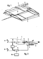
- FIG. 1 The arrangement shown in FIG. 1 is a section of the rear edge area of a transonic wing 1, on which a high-lift flap 2 and a spoiler 3 are arranged.
- the spoiler 3 lies tightly, ie without a gap, on the associated high-lift flap 2.
- the high lift flap 2 is only one here assigned hint 4, by means of which its position in relation to the wing can be changed in a defined manner.
- FIG. 2 Further details regarding the actuation of the flap system are shown in FIG. 2.
- the outer contour of the wing 1 is indicated by a dashed line.
- another actuating device 5 acting on the spoiler 3 is shown.
- the latter consists of a hydraulic piston system, while in this case the actuating device 4 for the high-lift flap 2 is designed as a mechanical drive unit with a spindle gear.
- both adjusting devices can be designed as desired within the scope of the invention.
- control and regulating device 6 for the high-lift flap 2 is connected to a computer system 10.
- this uses the current parameters such as flight altitude, speed and weight of the aircraft to determine the profile curvature that ensures optimum aerodynamic effectiveness of the wing in this flight phase and converts this into corresponding control signals that are sent to the control and regulating device 6 for the high-lift flap 2 are passed on.
- a coupling element 11 in the form of an electronic interface is arranged between the control and regulating devices 6 and 7.
- the input of this interface 11 is connected to a signal output of the control and regulating device 6 for the high-lift flap 2; its output is routed via an additional summation point 12 to the input of the control and regulating device 7 for the spoiler 3.
- this interface 11 contains, in the form of a polynomial, information about the geometrical relationship of the extension path of the high-lift flap 2 on the one hand and the width AZ of the gap formed between this flap 2 and the spoiler 3 when the flap is moved on the other hand.
- the position of the high-lift flap 2 in the cruise phase is determined by the computer system 10 checked. This transmits to the control and regulating device 6 those control signals which are necessary to move the high-lift flap 2 into a position which corresponds to the optimal profile curvature determined by the computer system 10 for the current flight situation. This leads to the fact that the high-lift flap 2 is moved, for example, into one of the positions indicated in FIG. 1 by means of the adjusting device 4.
- the interface 11 calculates on the basis of the information contained in the output signal of the control and regulating device 6 about the position of the high-lift flap 2 and on the basis of the stored geometric relationship between the flap position and the gap width AZ, an offset signal proportional to the calculated gap width, which at the summing point 12 in the control loop is used for spoiler control.
- This offset signal brings the spoiler 3 into a position in which the state that prevailed prior to the movement of the high-lift flap 2 is restored, that is to say in which the spoiler 3 rests on the high-lift flap 2 without an intermediate gap.
- the flap arrangement according to the invention naturally also includes systems in which, unlike in the exemplary embodiment of the invention described above, the function of the actuating levers 8 and 9 is taken over in whole or in part by an automatic aircraft guidance system.
- FIG. 3 Another exemplary embodiment of the invention, as in the arrangement shown in FIG. 3, is also a section of the trailing edge area of a transonic wing 1, on which a high-lift flap 2 and a spoiler 3 are arranged.
- the spoiler 3 lies tightly, that is to say without a gap, on the associated high-lift flap 2.
- the high-lift flap 2 is assigned an actuating device 4, which is only indicated here, by means of which its position in relation to the wing can be changed in a defined manner.
- FIG. 4 Further details regarding the actuation of the flap system are shown in FIG. 4.
- the outer contour of the wing 1 is indicated by a dashed line.
- Actuating device 4 shows another actuating device 5 acting on the spoiler 3.
- the latter consists of a hydraulic piston system, while in this case the actuating device 4 for the high-lift flap 2 is designed as a mechanical working unit with a spindle gear.
- both adjusting devices can be designed as desired within the scope of the invention.
- separate control and regulating devices 6 and 7 are connected upstream of the two actuating devices 4 and 5, which act on the associated actuating devices 4 and 5.
- two actuating levers 8 and 9 are provided in the cockpit, by means of which the positions of the high-lift flap 2 and the spoiler 3 can be set independently of one another in a known manner.
- control and regulating device 6 for the high-lift flap 2 is connected to a computer system 10.
- this uses the current parameters such as flight altitude, speed and weight of the aircraft to determine the profile curvature that ensures optimum aerodynamic effectiveness of the wing in this flight phase and converts this into corresponding control signals that are sent to the control and regulating device 6 for the high-lift flap 2 are passed on.
- control and regulating device 7 is assigned a coupling element in the form of a proximity sensor 21.
- the signal output of this proximity sensor 21 is routed to the input of the control device 7 for the spoiler 3.
- the proximity sensor 21 is arranged on the spoiler 3 and is aligned with the region 22 of the high-lift flap 2 opposite the spoiler 3.
- This area 22 can additionally be provided with a suitable covering or coating in order to optimize the effect of the proximity sensor 21.
- the arrangement of the parts 21 and 22 is of course interchanged, that is to say the proximity sensor 21 can be arranged on the high-lift flap 2 and the area 22 on the spoiler 3. In this case too, however, the signal output of the proximity sensor 21 would be connected to the input of the control device 7 for the spoiler 3.
- the position of the high-lift flap 2 in the cruise phase is determined by the computer system 10 controlled.
- the proximity sensor 21 in turn signals the control and regulating device 6 information about the distance to the high-lift flap 2.
- the signals can be transmitted as both electrical and optical signals. This signal causes the spoiler 3 to be brought into a position in which the state which prevailed before the high-lift flap 2 was moved is restored.
- this exemplary embodiment of the invention also includes systems in which, unlike in the flap system described above, the function of the actuating levers 8 and 9 is taken over in whole or in part by an automatic flight guidance system. Furthermore, in particular in the case of flap systems with a flexible spoiler, a plurality of proximity sensors 21 can be arranged on a flap.
Landscapes
- Engineering & Computer Science (AREA)
- Aviation & Aerospace Engineering (AREA)
- Automation & Control Theory (AREA)
- Transmission Devices (AREA)
- Body Structure For Vehicles (AREA)
Claims (8)
Applications Claiming Priority (4)
| Application Number | Priority Date | Filing Date | Title |
|---|---|---|---|
| DE3530864 | 1985-08-29 | ||
| DE19853530864 DE3530864A1 (de) | 1985-08-29 | 1985-08-29 | Klappenanordnung fuer einen flugzeugtragfluegel |
| DE3621401A DE3621401C1 (en) | 1986-06-26 | 1986-06-26 | Flap arrangement for an aircraft mainplane (wing) |
| DE3621401 | 1986-06-26 |
Publications (2)
| Publication Number | Publication Date |
|---|---|
| EP0218021A1 EP0218021A1 (fr) | 1987-04-15 |
| EP0218021B1 true EP0218021B1 (fr) | 1988-06-08 |
Family
ID=25835485
Family Applications (1)
| Application Number | Title | Priority Date | Filing Date |
|---|---|---|---|
| EP86109811A Expired EP0218021B1 (fr) | 1985-08-29 | 1986-07-17 | Agencement de volets pour aile d'avion |
Country Status (2)
| Country | Link |
|---|---|
| US (1) | US4720066A (fr) |
| EP (1) | EP0218021B1 (fr) |
Families Citing this family (40)
| Publication number | Priority date | Publication date | Assignee | Title |
|---|---|---|---|---|
| US5564656A (en) * | 1994-08-29 | 1996-10-15 | Gilbert; Raymond D. | Segmented spoilers |
| US5680124A (en) * | 1995-05-15 | 1997-10-21 | The Boeing Company | Skew and loss detection system for adjacent high lift devices |
| US5686907A (en) * | 1995-05-15 | 1997-11-11 | The Boeing Company | Skew and loss detection system for individual high lift devices |
| US6483436B1 (en) * | 2001-05-21 | 2002-11-19 | Hamilton Sundstrand Corporation | Method and apparatus for sensing skews and disconnects of adjacent movable components |
| US6672540B1 (en) | 2002-12-03 | 2004-01-06 | Rockwell Collins, Inc. | Actuator for aircraft stabilizers with a failure responsive lock control mechanism |
| US7243881B2 (en) * | 2003-06-03 | 2007-07-17 | The Boeing Company | Multi-function trailing edge devices and associated methods |
| FR2859976B1 (fr) * | 2003-09-22 | 2006-12-08 | Airbus France | Aile d'aeronef comportant au moins un volet deporteur et volet deporteur pour ladite aile |
| US6799739B1 (en) * | 2003-11-24 | 2004-10-05 | The Boeing Company | Aircraft control surface drive system and associated methods |
| US7424350B2 (en) * | 2004-02-02 | 2008-09-09 | The Boeing Company | Vehicle control systems and corresponding sizing methods |
| US7357358B2 (en) * | 2004-02-27 | 2008-04-15 | The Boeing Company | Aircraft leading edge device systems and corresponding sizing methods |
| US7270305B2 (en) * | 2004-06-15 | 2007-09-18 | The Boeing Company | Aircraft leading edge apparatuses and corresponding methods |
| US7494094B2 (en) * | 2004-09-08 | 2009-02-24 | The Boeing Company | Aircraft wing systems for providing differential motion to deployable lift devices |
| US7264206B2 (en) * | 2004-09-30 | 2007-09-04 | The Boeing Company | Leading edge flap apparatuses and associated methods |
| US7322547B2 (en) * | 2005-01-31 | 2008-01-29 | The Boeing Company | Aerospace vehicle leading edge slat devices and corresponding methods |
| US7338018B2 (en) * | 2005-02-04 | 2008-03-04 | The Boeing Company | Systems and methods for controlling aircraft flaps and spoilers |
| US7500641B2 (en) * | 2005-08-10 | 2009-03-10 | The Boeing Company | Aerospace vehicle flow body systems and associated methods |
| US7611099B2 (en) * | 2005-09-07 | 2009-11-03 | The Boeing Company | Seal assemblies for use with drooped spoilers and other control surfaces on aircraft |
| DE102005045759A1 (de) * | 2005-09-23 | 2007-04-12 | Airbus Deutschland Gmbh | Fortschrittlicheflügelhinterkante am Flügel eines Flugzeugs |
| US7709210B2 (en) * | 2005-10-05 | 2010-05-04 | Children's Hospital Medical Center | Diagnosis and prevention of fetal heart disease |
| US7475854B2 (en) * | 2005-11-21 | 2009-01-13 | The Boeing Company | Aircraft trailing edge devices, including devices with non-parallel motion paths, and associated methods |
| US7708231B2 (en) | 2005-11-21 | 2010-05-04 | The Boeing Company | Aircraft trailing edge devices, including devices having forwardly positioned hinge lines, and associated methods |
| GB0722415D0 (en) * | 2007-11-15 | 2007-12-27 | Airbus Uk Ltd | Aircraft wing and flap deployment system |
| US20140339358A1 (en) * | 2007-12-06 | 2014-11-20 | Roller Bearing Company Of America, Inc. | Electrical conductor for lined track rollers used on actuation system for aircraft lift assisting devices |
| US20140131512A1 (en) * | 2007-12-06 | 2014-05-15 | Roller Bearing Company Of America, Inc. | Seal and electrical conductor for lined track rollers used on actuation system for aircraft lift assisting devices |
| US7954769B2 (en) | 2007-12-10 | 2011-06-07 | The Boeing Company | Deployable aerodynamic devices with reduced actuator loads, and related systems and methods |
| US7766282B2 (en) * | 2007-12-11 | 2010-08-03 | The Boeing Company | Trailing edge device catchers and associated systems and methods |
| US8382045B2 (en) | 2009-07-21 | 2013-02-26 | The Boeing Company | Shape-changing control surface |
| DE102009060325A1 (de) | 2009-12-23 | 2011-06-30 | Airbus Operations GmbH, 21129 | Hochauftriebssystem für ein Flugzeug |
| DE102009060326A1 (de) * | 2009-12-23 | 2011-06-30 | Airbus Operations GmbH, 21129 | Hochauftriebssystem für ein Flugzeug |
| DE102010010577A1 (de) * | 2010-03-08 | 2011-09-08 | Airbus Operations Gmbh | Hochauftriebssystem für ein Flugzeug |
| GB201108450D0 (en) * | 2011-05-20 | 2011-07-06 | Airbus Operations Ltd | Aircraft wing assembly |
| US8438743B2 (en) | 2011-06-01 | 2013-05-14 | Hamilton Sundstrand Corporation | Resolver type skew sensor with gimbal attachment |
| US9108715B2 (en) * | 2012-05-29 | 2015-08-18 | The Boeing Company | Rotary actuated high lift gapped aileron |
| US9688384B1 (en) * | 2012-09-20 | 2017-06-27 | The Boeing Company | Methods and apparatus to control a gap between movable aircraft wing components |
| US10501166B2 (en) | 2012-09-20 | 2019-12-10 | The Boeing Company | Methods and apparatus to control a gap between movable aircraft wing components |
| US9994304B2 (en) * | 2014-10-01 | 2018-06-12 | Nabtesco Corporation | Hydraulic actuator |
| JP6424079B2 (ja) * | 2014-11-28 | 2018-11-14 | ナブテスコ株式会社 | 油圧アクチュエータ |
| JP6362986B2 (ja) * | 2014-10-01 | 2018-07-25 | ナブテスコ株式会社 | 油圧アクチュエータ |
| US20200307775A1 (en) * | 2017-11-21 | 2020-10-01 | Bombardier Inc. | System and method for actuating high-lift flight control surfaces |
| CN115384757B (zh) * | 2022-10-31 | 2023-01-24 | 北京启时智航科技有限公司 | 襟副翼作动机构及机翼结构 |
Citations (1)
| Publication number | Priority date | Publication date | Assignee | Title |
|---|---|---|---|---|
| DE3114143A1 (de) * | 1981-04-08 | 1982-10-28 | Vereinigte Flugtechnische Werke Gmbh, 2800 Bremen | "verfahren zur optimierung des reiseflugzustandes von flugzeugen mit transsonischen tragfluegeln sowie vorrichtung zur durchfuehrung des verfahrens" |
Family Cites Families (5)
| Publication number | Priority date | Publication date | Assignee | Title |
|---|---|---|---|---|
| FR2101001B1 (fr) * | 1970-08-05 | 1973-05-25 | Mitsubishi Heavy Ind Ltd | Aile d'avion |
| US3987983A (en) * | 1974-12-20 | 1976-10-26 | The Boeing Company | Trailing edge flaps having spanwise aerodynamic slot opening and closing mechanism |
| US4120470A (en) * | 1976-09-28 | 1978-10-17 | The Boeing Company | Efficient trailing edge system for an aircraft wing |
| GB1568250A (en) * | 1976-12-15 | 1980-05-29 | Hawker Siddeley Aviation Ltd | Aircraft |
| US4363098A (en) * | 1980-06-24 | 1982-12-07 | The Boeing Company | Electric command spoiler system |
-
1986
- 1986-07-17 EP EP86109811A patent/EP0218021B1/fr not_active Expired
- 1986-08-26 US US06/900,507 patent/US4720066A/en not_active Expired - Fee Related
Patent Citations (1)
| Publication number | Priority date | Publication date | Assignee | Title |
|---|---|---|---|---|
| DE3114143A1 (de) * | 1981-04-08 | 1982-10-28 | Vereinigte Flugtechnische Werke Gmbh, 2800 Bremen | "verfahren zur optimierung des reiseflugzustandes von flugzeugen mit transsonischen tragfluegeln sowie vorrichtung zur durchfuehrung des verfahrens" |
Also Published As
| Publication number | Publication date |
|---|---|
| EP0218021A1 (fr) | 1987-04-15 |
| US4720066A (en) | 1988-01-19 |
Similar Documents
| Publication | Publication Date | Title |
|---|---|---|
| EP0218021B1 (fr) | Agencement de volets pour aile d'avion | |
| EP0215211B1 (fr) | Dispositif d'actionnement et de guidage pour un ensemble de volets disposés sur une aile d'avion | |
| DE69020537T2 (de) | Klappe- und querrudersystem eines flügels für ein verwandlungsflugzeug. | |
| DE69707196T2 (de) | Ausgleichrudersteuerung für Flugzeuge | |
| DE4422152C2 (de) | Verfahren und Anordnung zum Optimieren der aerodynamischen Wirkung eines Tragflügels | |
| DE10313728B4 (de) | Klappensystem am Tragflügel eines Starrflügel-Flugzeuges | |
| DE3522448C2 (fr) | ||
| DE3430377C2 (fr) | ||
| EP0503158B1 (fr) | Système d'entraînement et de guide pour un volet d'aile d'avion | |
| DE60023896T2 (de) | Fahrzeugsteuerungssystem und -verfahren unter verwendung einer steuerfläche und einer hilfssteuerfläche mit übersetzung | |
| DE2703565A1 (de) | Flugsteuersystem | |
| EP2280867B1 (fr) | Dispositif de couplage latéral pour maintenir et guider au moins un corps aérodynamique par rapport à une aile principale d'un aéronef, voilure et aéronef comprenant ledit dispositif | |
| DE60104808T2 (de) | System zur automatischen Steuerung von Hochauftriebsklappen eines Flugzeugs während des Starts | |
| DE3114143A1 (de) | "verfahren zur optimierung des reiseflugzustandes von flugzeugen mit transsonischen tragfluegeln sowie vorrichtung zur durchfuehrung des verfahrens" | |
| DE3641247A1 (de) | Landeklappenfuehrungsschienen-verkleidung fuer luftfahrzeuge | |
| EP1619117A1 (fr) | Mécanisme de couplage pour volets d'avion | |
| EP2368793A2 (fr) | Véhicule aérien habité | |
| DE3310510C2 (fr) | ||
| DE2914974C2 (de) | Kombinierte Auftriebs- bzw. Steuerklappe, insbesondere an der Hinterkante von Flugzeugtragflügeln | |
| DE3530864C2 (fr) | ||
| DE3621401C1 (en) | Flap arrangement for an aircraft mainplane (wing) | |
| EP0216033B1 (fr) | Agencement de volets pour aile d'avion | |
| DE69813090T2 (de) | Seitenleitwerkanordnung für Flugzeuge | |
| DE3133961A1 (de) | "betaetigungsanordnung fuer fluegelklappen" | |
| DE19857644C2 (de) | Passagierflugzeug mit geradem oder gepfeiltem Entenleitwerk |
Legal Events
| Date | Code | Title | Description |
|---|---|---|---|
| PUAI | Public reference made under article 153(3) epc to a published international application that has entered the european phase |
Free format text: ORIGINAL CODE: 0009012 |
|
| AK | Designated contracting states |
Kind code of ref document: A1 Designated state(s): FR GB IT NL |
|
| 17P | Request for examination filed |
Effective date: 19870310 |
|
| 17Q | First examination report despatched |
Effective date: 19871124 |
|
| GRAA | (expected) grant |
Free format text: ORIGINAL CODE: 0009210 |
|
| AK | Designated contracting states |
Kind code of ref document: B1 Designated state(s): FR GB IT NL |
|
| ET | Fr: translation filed | ||
| GBT | Gb: translation of ep patent filed (gb section 77(6)(a)/1977) | ||
| ITF | It: translation for a ep patent filed | ||
| PLBE | No opposition filed within time limit |
Free format text: ORIGINAL CODE: 0009261 |
|
| STAA | Information on the status of an ep patent application or granted ep patent |
Free format text: STATUS: NO OPPOSITION FILED WITHIN TIME LIMIT |
|
| 26N | No opposition filed | ||
| ITTA | It: last paid annual fee | ||
| PGFP | Annual fee paid to national office [announced via postgrant information from national office to epo] |
Ref country code: GB Payment date: 19950711 Year of fee payment: 10 |
|
| PGFP | Annual fee paid to national office [announced via postgrant information from national office to epo] |
Ref country code: FR Payment date: 19950731 Year of fee payment: 10 |
|
| PGFP | Annual fee paid to national office [announced via postgrant information from national office to epo] |
Ref country code: NL Payment date: 19951206 Year of fee payment: 10 |
|
| PG25 | Lapsed in a contracting state [announced via postgrant information from national office to epo] |
Ref country code: GB Effective date: 19960717 |
|
| PG25 | Lapsed in a contracting state [announced via postgrant information from national office to epo] |
Ref country code: NL Effective date: 19970201 |
|
| GBPC | Gb: european patent ceased through non-payment of renewal fee |
Effective date: 19960717 |
|
| PG25 | Lapsed in a contracting state [announced via postgrant information from national office to epo] |
Ref country code: FR Effective date: 19970328 |
|
| NLV4 | Nl: lapsed or anulled due to non-payment of the annual fee |
Effective date: 19970201 |
|
| REG | Reference to a national code |
Ref country code: FR Ref legal event code: ST |
|
| PG25 | Lapsed in a contracting state [announced via postgrant information from national office to epo] |
Ref country code: IT Free format text: LAPSE BECAUSE OF NON-PAYMENT OF DUE FEES;WARNING: LAPSES OF ITALIAN PATENTS WITH EFFECTIVE DATE BEFORE 2007 MAY HAVE OCCURRED AT ANY TIME BEFORE 2007. THE CORRECT EFFECTIVE DATE MAY BE DIFFERENT FROM THE ONE RECORDED. Effective date: 20050717 |