EP0217515B1 - Support for writing desks - Google Patents
Support for writing desks Download PDFInfo
- Publication number
- EP0217515B1 EP0217515B1 EP86306253A EP86306253A EP0217515B1 EP 0217515 B1 EP0217515 B1 EP 0217515B1 EP 86306253 A EP86306253 A EP 86306253A EP 86306253 A EP86306253 A EP 86306253A EP 0217515 B1 EP0217515 B1 EP 0217515B1
- Authority
- EP
- European Patent Office
- Prior art keywords
- members
- end portion
- modular element
- support
- elongated modular
- Prior art date
- Legal status (The legal status is an assumption and is not a legal conclusion. Google has not performed a legal analysis and makes no representation as to the accuracy of the status listed.)
- Expired - Lifetime
Links
- 238000010276 construction Methods 0.000 description 3
- 230000000712 assembly Effects 0.000 description 1
- 238000000429 assembly Methods 0.000 description 1
- 238000012423 maintenance Methods 0.000 description 1
- 238000012986 modification Methods 0.000 description 1
- 230000004048 modification Effects 0.000 description 1
- 238000003466 welding Methods 0.000 description 1
Images




Classifications
-
- A—HUMAN NECESSITIES
- A47—FURNITURE; DOMESTIC ARTICLES OR APPLIANCES; COFFEE MILLS; SPICE MILLS; SUCTION CLEANERS IN GENERAL
- A47B—TABLES; DESKS; OFFICE FURNITURE; CABINETS; DRAWERS; GENERAL DETAILS OF FURNITURE
- A47B21/00—Tables or desks for office equipment, e.g. typewriters, keyboards
- A47B21/06—Tables or desks for office equipment, e.g. typewriters, keyboards characterised by means for holding, fastening or concealing cables
-
- F—MECHANICAL ENGINEERING; LIGHTING; HEATING; WEAPONS; BLASTING
- F16—ENGINEERING ELEMENTS AND UNITS; GENERAL MEASURES FOR PRODUCING AND MAINTAINING EFFECTIVE FUNCTIONING OF MACHINES OR INSTALLATIONS; THERMAL INSULATION IN GENERAL
- F16B—DEVICES FOR FASTENING OR SECURING CONSTRUCTIONAL ELEMENTS OR MACHINE PARTS TOGETHER, e.g. NAILS, BOLTS, CIRCLIPS, CLAMPS, CLIPS OR WEDGES; JOINTS OR JOINTING
- F16B2200/00—Constructional details of connections not covered for in other groups of this subclass
- F16B2200/50—Flanged connections
- F16B2200/506—Flanged connections bolted or riveted
-
- Y—GENERAL TAGGING OF NEW TECHNOLOGICAL DEVELOPMENTS; GENERAL TAGGING OF CROSS-SECTIONAL TECHNOLOGIES SPANNING OVER SEVERAL SECTIONS OF THE IPC; TECHNICAL SUBJECTS COVERED BY FORMER USPC CROSS-REFERENCE ART COLLECTIONS [XRACs] AND DIGESTS
- Y10—TECHNICAL SUBJECTS COVERED BY FORMER USPC
- Y10T—TECHNICAL SUBJECTS COVERED BY FORMER US CLASSIFICATION
- Y10T403/00—Joints and connections
- Y10T403/57—Distinct end coupler
Definitions
- the present invention relates to support for writing desks or tables of variable configuration, comprising a longitudinal support which extends beneath worktop portion and which structurally connects legs and worktop portions and more specifically as set forth in the introductory part of claim 1.
- a support for writing desks within which are disposed electrical and telephone cables and electrical power distribution units. That support suffers from the disadvantage that access to the cables or to the distribution units is difficult once they have been housed in the support. In the event of damage or failure or when fresh connections are required, fresh cables and distribution units are therefore necessary, which are mounted on the outside with clearly apparent additional clutter and obstructions and ugly overall results.
- a support according to the introductory part of claim 1 is known from EP 0 108 559 but is of complex construction and requires fabricated T or crosspieces where elongated modular elements are to be connected together perpendicular to each other.
- EP 0 123 972 describes a construction in which the end of a lateral elongated modular element may be clipped on to the side of a central elongated modular element where desired but without provision for extending cables ito the lateral element.
- the object of the present invention is to provide a support for writing desks and tables which is suitable for housing electrical cables extending also into lateral elongated modular elements and which is simple, reliable and low in cost and which permits modular assembly and easy access to the cables for maintenance operations or for making fresh connections.
- the support for writing desks and tables of variable configuration in accordance with the invention, is characterized in claim 1 below.
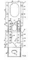
- the support for writing desks and tables of variable configuration is generally indicated by reference numeral 11 and comprises a modular element of predetermined length with a cross-section in the form of an inverted omega.
- the modular element 11 comprises a base 12 and two side walls 13 and 14 which each terminate with an external edge or limb portion 16 and 17 substantially parallel to the base 12.
- the members 15 define connecting elements 18 of the support and are capable of being connected in known manner, for example by means of screws (not always shown in the drawings) either to flanges of tubular legs 19 (see Figure 6) or to box-like legs 21 or to load-bearing drawer units 22 (see Figure 5).
- the element 18 can be connected to a further connecting element 18 of a second modular element 11 (see Figure 1), an interconnection module 41 (see Figure 3) or a terminal module 61 (see Figure 4).
- the modular element 11 extends longitudinally beneath a worktop portion 23 (see Figure 5) and structurally connects the tubular legs 19 (see Figure 6) or the box legs 21 or the load-bearing drawer units 22 . (see Figure 5), to the worktop portions 23.
- each connecting element 18 has a series of holes 24 for fixing the modular element 11 either to a plate 26 (see Figure 2) which is fixed with respect to the end of the tubular leg 19 or to the box-like legs 21 (see Figure 6) or to the load-bearing drawer units 22 (see Figure 5).
- Each edge portion 16 and 17 has a series of holes 27 for receiving screws (not shown in the drawings) for fixing the modular element 11 to the worktop portion 23 (see Figures 5 and 6).
- the modular element 11 operates as a containing means for electrical cables 28 (see Figure 2) and telephone cables 29, and can house electrical power distribution units 31 at various points therein and permits the passage of outlets or sockets 32 and cables 33 at various points. That is possible because each modular element 11 is provided in the length thereof with various large openings or slots 36 and 37 which are provided respectively in the base 12 and the side walls 13 and 14. The size of the openings 36 and 37 is such as also to permit the hands of the operator to pass therethrough, so that the operator can thus make various connections to the distribution units 31 by means of the outlets 32 and can therefore come out with various cables 33 depending on the requirements involved and the positions of the machines standing on the worktop portions 23.
- Figure 2 shows two electrical cables 28, a telephone cable 29, a distribution unit 31 and two outlets or sockets 32 connected to cables 33. That representation is given purely by way of non-limiting ex - ample, for the purpose of the present invention.
- Some of the connecting elements 18 have an opening or slot 38 which is disposed between the holes 24 and which communicates with a hole 39 (see Figure 2) of the tubular leg 19 or with holes (not shown) of the box legs 21 (see Figure 5) and the drawer units 22 to permit the passage therethrough of electrical and telephone cables for connection to other writing desks 23.
- the openings 36, 37 ( Figure 1) and 38 have their edges turned over inwardly (not shown in the drawings), which strengthen the support and avoid the cables being accidentally cut during handling thereof.
- FIG. 3 shows a connection between two modular elements 11 which are disposed perpendicularly relative to each other, by means of the interconnection module 41 and one of a series of connecting portions 40 of one of the two modular elements 11. That form of connection makes it possible to produce writing desks of variable configurations as diagrammatically indicated in Figures 7 and 8, as will be described hereinafter.
- the interconnection module 41 (see Figure 3) is of predetermined length and the section in the form of an inverted omega is substantially similar to that of the modular element 11. Indeed, it comprises a base 42 and two side walls 43 and 44 which terminate with edge portions 46 and 47 having holes 48 for fixing the worktop portion 23.
- the module 41 is also provided with a connecting element 18.
- the two modules 11 and 41 are connected in aligned relationship by means of a pair of C-shaped members 20 which are fixed in known manner, for example by means of screws 35, to the C-shaped members 15 which define the elements 18 of the two modules 11 and 41.
- the lateral connecting portions 40 each comprise an opening or slot 37 and a plurality of holes 54 around each opening.
- the interconnection module 47 in turn comprises a flange 51 by means of which it is fixed by screws 52 and the holes 54 in the lateral connecting portion 40, to the side walls 13 or 14 of the modular element 11.
- the flange 51 defines a slot or opening 53 which is aligned with the opening 37 in the portion 40. That arrangement thus provides a strong and easily dismantlable connection.
- the openings 37 and 53 define a large aperture for the cables 28 and 29 to pass therethrough.
- FIG 4 shown therein is a connection between the connecting element 18 of a modular element 11 and the terminal module 61.
- This connection makes it possible to connect square or rectangular worktop portions to semicircular worktop portions in an array of writing desks of variable configuration, as diagrammatically shown in Figures 7 and 8.
- the terminal module 61 ( Figure 4) has a portion formed by a shaped member with a cross-section in the form of an inverted omega, substantially similar to that of the modular element 11, and comprises a base 62 and two side walls 63 and 64 which terminate with edge portions 66 and 67 having holes 68 for fixing the worktop portion.
- the module 61 is provided at one of the ends thereof with a connecting element 18 which can be connected to the connecting element 18 of the support 11 by means of screws and a pair of shaped members 20.
- the other end of the module 61 terminates with a front inclined wall; portion 69 having a hole or seat 71 for the cables 28 and 29 to pass therethrough.
- Figures 5, 6, 7 and 8 diagrammatically show various constructions which provide for assembly of the modular element 11 to straightforward worktop portions 23 or worktop portions of variable configurations.
- the modular element 11 is structurally connected to the box leg 21, to the load-bearing drawer unit 22 and to the worktop portion 23.
- the modular element 11 is structurally connected to the tubular leg 19, to the box leg 21, to a suspended drawer unit 76 and to a worktop portion 77. In such cases, the visible ends of the support 11 are closed by a cover element (not shown in the drawings).
- the modular element 11 is structurally connected to a load-bearing drawer unit 78, to a tubular leg 79, to a worktop portion 81 and, by means of an interconnection module 41, to a lateral connecting portion 40 of a second modular element 11' which is perpendicular to the first modular element 11.
- the module 11' is in turn structurally connected to a load-bearing drawer unit 82, to a tubular leg 83, to a worktop portion 84 and, by means of a second interconnection module 41', to a second lateral connecting portion 40' of a third modular element 11" which is perpendicular to the second modular element 11'.
- the modular element 11" is finally structurally connected to a box leg 86, to a load-bearing drawer unit 87, to a worktop portion 88 and, by means of a terminal module 61, to a semicircular worktop portion 89.
- the modular element 11 is structural connected to a load-bearing drawer unit 91, to a tubular leg 92, to a worktop portion 93, and, by means of a terminal module 61, to a semicircular worktop portion 94, and, by means of an interconnection module 41 and the lateral connecting portion 40, it is further structurally connected to a second modular element 11' which is perpendicular to the first modular element 11.
- the second element 11' is in turn structurally connected to a load-bearing drawer unit 96, to a tubular leg 97, to a worktop portion 98, to a second terminal module 61' and to the semicircular worktop portion 99.
- the first modular element 11 is also connected by means of a second interconnection module 41' and a lateral connecting portion 40' to a third modular element 11" which is perpendicular to the first modular element 11 and parallel to the second modular element 11'.
- the last element 11" is finally structurally connected to a tubular leg 101, to a load-bearing drawer unit 102, to a worktop portion 103, to a third terminal module 61' and to the semicircular worktop portion 104.
- the support or modular element 11 of the present invention represents an essential part of a strong, compact, functional and practical structure for producing writing desks and tables of variable configurations. Furthermore the combinations which can be produced are not limited solely to those illustrated in the drawings, but they may extend to more or less complex and close-packed assemblies, providing variable and unlimited configurations.
Landscapes
- Tables And Desks Characterized By Structural Shape (AREA)
Description
- The present invention relates to support for writing desks or tables of variable configuration, comprising a longitudinal support which extends beneath worktop portion and which structurally connects legs and worktop portions and more specifically as set forth in the introductory part of
claim 1. - A support for writing desks is known, within which are disposed electrical and telephone cables and electrical power distribution units. That support suffers from the disadvantage that access to the cables or to the distribution units is difficult once they have been housed in the support. In the event of damage or failure or when fresh connections are required, fresh cables and distribution units are therefore necessary, which are mounted on the outside with clearly apparent additional clutter and obstructions and ugly overall results.
- A support according to the introductory part of
claim 1 is known from EP 0 108 559 but is of complex construction and requires fabricated T or crosspieces where elongated modular elements are to be connected together perpendicular to each other. - EP 0 123 972 describes a construction in which the end of a lateral elongated modular element may be clipped on to the side of a central elongated modular element where desired but without provision for extending cables ito the lateral element. The object of the present invention is to provide a support for writing desks and tables which is suitable for housing electrical cables extending also into lateral elongated modular elements and which is simple, reliable and low in cost and which permits modular assembly and easy access to the cables for maintenance operations or for making fresh connections.
- The support for writing desks and tables of variable configuration, in accordance with the invention, is characterized in
claim 1 below. - A preferred embodiment of the invention is set forth in the following description which is given by way of non-limiting example with reference to the accompanying drawings in which:
- Figure 1 shows a plan view of part of the support according to the invention, with a first type of connection,
- Figure 2 is a view in section of part of the support shown in Figure 1, connected to a tubular support leg,
- Figure 3 is a plan view of part of the support shown in Figure 1, with another type of connection,
- Figure 4 is a plan view of part of the support shown in Figure 1, with a further type of connection,
- Figure 5 is a diagrammatic view of a writing desk with the support shown in Figure 1,
- Figure 6 is a diagrammatic view of another writing desk with the support shown in Figure 1,
- Figure 7 is a diagrammatic view of a type of writing desks integrated with the support or the connections shown in Figures 3 and 4,
- Figure 8 is a diagrammatic view of another type of writing desks integrated with the support and the connections shown in Figures 3 and 4, and
- Figure 9 is a diagrammatic view in section of the support shown in Figure 1.
- Referring to Figures 1 and 2, the support for writing desks and tables of variable configuration is generally indicated by
reference numeral 11 and comprises a modular element of predetermined length with a cross-section in the form of an inverted omega. - The
modular element 11 comprises abase 12 and twoside walls limb portion base 12. Fixed to the ends of themodular element 11, for example by welding, are two members of C-shape section, as indicated at 15, with a stiffening function. Themembers 15 define connectingelements 18 of the support and are capable of being connected in known manner, for example by means of screws (not always shown in the drawings) either to flanges of tubular legs 19 (see Figure 6) or to box-like legs 21 or to load-bearing drawer units 22 (see Figure 5). In addition, by means of a pair of further C-shaped members as indicated at 20, the element 18 (see Figure 1) can be connected to a further connectingelement 18 of a second modular element 11 (see Figure 1), an interconnection module 41 (see Figure 3) or a terminal module 61 (see Figure 4). - The
modular element 11 extends longitudinally beneath a worktop portion 23 (see Figure 5) and structurally connects the tubular legs 19 (see Figure 6) or thebox legs 21 or the load-bearingdrawer units 22 . (see Figure 5), to theworktop portions 23. For that purpose, each connecting element 18 (see Figure 1) has a series ofholes 24 for fixing themodular element 11 either to a plate 26 (see Figure 2) which is fixed with respect to the end of thetubular leg 19 or to the box-like legs 21 (see Figure 6) or to the load-bearing drawer units 22 (see Figure 5). Eachedge portion 16 and 17 (see Figure 1) has a series ofholes 27 for receiving screws (not shown in the drawings) for fixing themodular element 11 to the worktop portion 23 (see Figures 5 and 6). - The
modular element 11 operates as a containing means for electrical cables 28 (see Figure 2) andtelephone cables 29, and can house electricalpower distribution units 31 at various points therein and permits the passage of outlets orsockets 32 andcables 33 at various points. That is possible because eachmodular element 11 is provided in the length thereof with various large openings orslots base 12 and theside walls openings distribution units 31 by means of theoutlets 32 and can therefore come out withvarious cables 33 depending on the requirements involved and the positions of the machines standing on theworktop portions 23. - Figure 2 shows two
electrical cables 28, atelephone cable 29, adistribution unit 31 and two outlets orsockets 32 connected tocables 33. That representation is given purely by way of non-limiting ex- ample, for the purpose of the present invention. - Some of the connecting elements 18 (see Figure 1) have an opening or
slot 38 which is disposed between theholes 24 and which communicates with a hole 39 (see Figure 2) of thetubular leg 19 or with holes (not shown) of the box legs 21 (see Figure 5) and thedrawer units 22 to permit the passage therethrough of electrical and telephone cables for connection toother writing desks 23. Theopenings 36, 37 (Figure 1) and 38 have their edges turned over inwardly (not shown in the drawings), which strengthen the support and avoid the cables being accidentally cut during handling thereof. - Reference is now made to Figure 3 which shows a connection between two
modular elements 11 which are disposed perpendicularly relative to each other, by means of theinterconnection module 41 and one of a series of connectingportions 40 of one of the twomodular elements 11. That form of connection makes it possible to produce writing desks of variable configurations as diagrammatically indicated in Figures 7 and 8, as will be described hereinafter. - The interconnection module 41 (see Figure 3) is of predetermined length and the section in the form of an inverted omega is substantially similar to that of the
modular element 11. Indeed, it comprises abase 42 and twoside walls edge portions 46 and 47 havingholes 48 for fixing theworktop portion 23. In addition themodule 41 is also provided with a connectingelement 18. The twomodules shaped members 20 which are fixed in known manner, for example by means ofscrews 35, to the C-shaped members 15 which define theelements 18 of the twomodules - The lateral connecting
portions 40 each comprise an opening orslot 37 and a plurality ofholes 54 around each opening. Theinterconnection module 47 in turn comprises aflange 51 by means of which it is fixed byscrews 52 and theholes 54 in the lateral connectingportion 40, to theside walls modular element 11. Theflange 51 defines a slot or opening 53 which is aligned with theopening 37 in theportion 40. That arrangement thus provides a strong and easily dismantlable connection. Theopenings cables - Referring now to Figure 4, shown therein is a connection between the connecting
element 18 of amodular element 11 and theterminal module 61. This connection makes it possible to connect square or rectangular worktop portions to semicircular worktop portions in an array of writing desks of variable configuration, as diagrammatically shown in Figures 7 and 8. - The terminal module 61 (Figure 4) has a portion formed by a shaped member with a cross-section in the form of an inverted omega, substantially similar to that of the
modular element 11, and comprises abase 62 and twoside walls edge portions holes 68 for fixing the worktop portion. Themodule 61 is provided at one of the ends thereof with a connectingelement 18 which can be connected to the connectingelement 18 of thesupport 11 by means of screws and a pair ofshaped members 20. The other end of themodule 61 terminates with a front inclined wall;portion 69 having a hole orseat 71 for thecables - Figures 5, 6, 7 and 8 diagrammatically show various constructions which provide for assembly of the
modular element 11 tostraightforward worktop portions 23 or worktop portions of variable configurations. In particular, in Figure 5, themodular element 11 is structurally connected to thebox leg 21, to the load-bearingdrawer unit 22 and to theworktop portion 23. In Figure 6, themodular element 11 is structurally connected to thetubular leg 19, to thebox leg 21, to a suspendeddrawer unit 76 and to aworktop portion 77. In such cases, the visible ends of thesupport 11 are closed by a cover element (not shown in the drawings). - In Figure 7, the
modular element 11 is structurally connected to a load-bearingdrawer unit 78, to atubular leg 79, to aworktop portion 81 and, by means of aninterconnection module 41, to a lateral connectingportion 40 of a second modular element 11' which is perpendicular to the firstmodular element 11. The module 11' is in turn structurally connected to a load-bearingdrawer unit 82, to atubular leg 83, to aworktop portion 84 and, by means of a second interconnection module 41', to a second lateral connecting portion 40' of a thirdmodular element 11" which is perpendicular to the second modular element 11'. Themodular element 11" is finally structurally connected to a box leg 86, to a load-bearingdrawer unit 87, to aworktop portion 88 and, by means of aterminal module 61, to asemicircular worktop portion 89. - In figure 8, the
modular element 11 is structural connected to a load-bearingdrawer unit 91, to atubular leg 92, to aworktop portion 93, and, by means of aterminal module 61, to asemicircular worktop portion 94, and, by means of aninterconnection module 41 and the lateral connectingportion 40, it is further structurally connected to a second modular element 11' which is perpendicular to the firstmodular element 11. The second element 11' is in turn structurally connected to a load-bearingdrawer unit 96, to atubular leg 97, to aworktop portion 98, to a second terminal module 61' and to thesemicircular worktop portion 99. The firstmodular element 11 is also connected by means of a second interconnection module 41' and a lateral connecting portion 40' to a thirdmodular element 11" which is perpendicular to the firstmodular element 11 and parallel to the second modular element 11'. Thelast element 11" is finally structurally connected to atubular leg 101, to a load-bearingdrawer unit 102, to aworktop portion 103, to a third terminal module 61' and to thesemicircular worktop portion 104. - The support or
modular element 11 of the present invention represents an essential part of a strong, compact, functional and practical structure for producing writing desks and tables of variable configurations. Furthermore the combinations which can be produced are not limited solely to those illustrated in the drawings, but they may extend to more or less complex and close-packed assemblies, providing variable and unlimited configurations. - It will be appreciated that the support for writing desks and tables or variable configurations as described herein may be the subject of modifications and improvements both in regard to the form and the arrangement of the various parts without thereby departing from the scope of the invention.
Claims (6)
Applications Claiming Priority (2)
| Application Number | Priority Date | Filing Date | Title |
|---|---|---|---|
| IT67789/85A IT1183963B (en) | 1985-09-18 | 1985-09-18 | SUPPORT FOR DESKS |
| IT6778985 | 1985-09-18 |
Publications (2)
| Publication Number | Publication Date |
|---|---|
| EP0217515A1 EP0217515A1 (en) | 1987-04-08 |
| EP0217515B1 true EP0217515B1 (en) | 1990-01-03 |
Family
ID=11305305
Family Applications (1)
| Application Number | Title | Priority Date | Filing Date |
|---|---|---|---|
| EP86306253A Expired - Lifetime EP0217515B1 (en) | 1985-09-18 | 1986-08-13 | Support for writing desks |
Country Status (4)
| Country | Link |
|---|---|
| US (1) | US4836481A (en) |
| EP (1) | EP0217515B1 (en) |
| DE (1) | DE3667904D1 (en) |
| IT (1) | IT1183963B (en) |
Families Citing this family (9)
| Publication number | Priority date | Publication date | Assignee | Title |
|---|---|---|---|---|
| DK511989A (en) * | 1988-10-17 | 1990-04-18 | Protoned Bv | WORK |
| DE19547052A1 (en) * | 1995-12-18 | 1997-06-19 | Ver Spezialmoebel Verwalt | Adjustable table system |
| WO2001087226A2 (en) | 2000-05-18 | 2001-11-22 | Wilson-Cook Medical Inc. | Percutaneous gastrostomy device and method |
| RU2246888C1 (en) * | 2004-03-12 | 2005-02-27 | Общество с ограниченной ответственностью "Проммебель" | Office table (versions) |
| ITBO20040401A1 (en) * | 2004-06-25 | 2004-09-25 | Metal Work Srl | FASTENING SYSTEM FOR MODULAR STRUCTURES, IN PARTICULAR TABLES, DESKS AND SIMILAR |
| US20060260519A1 (en) * | 2005-05-17 | 2006-11-23 | Burns Martin P | Sheet metal table top stiffener |
| EP1951087A2 (en) * | 2005-11-22 | 2008-08-06 | Buzstudios LLC | Office furniture system |
| NL2003594C2 (en) * | 2009-10-05 | 2011-11-29 | Markant Nederland B V | WORKPLACE COMPOSITION AND METHOD. |
| JP6124554B2 (en) * | 2012-10-31 | 2017-05-10 | コクヨ株式会社 | Table system |
Family Cites Families (15)
| Publication number | Priority date | Publication date | Assignee | Title |
|---|---|---|---|---|
| US1201703A (en) * | 1914-07-01 | 1916-10-17 | James L Davidson | Sectional metal shelving. |
| US3082712A (en) * | 1958-03-24 | 1963-03-26 | Richard E Dentsch | Modular work bench with stringers connecting frame elements |
| FR1436034A (en) * | 1965-03-11 | 1966-04-22 | Teclab | Process for the construction of laboratory tables by means of prefabricated elements as well as elements and devices for carrying out this process |
| FR1477591A (en) * | 1966-03-01 | 1967-04-21 | Connection method for building elements, in particular tubular, and device for carrying out this method | |
| US3413813A (en) * | 1966-03-09 | 1968-12-03 | Pittsburgh Des Moines Steel | Tunnel support including a yieldable connection |
| US3711133A (en) * | 1971-06-02 | 1973-01-16 | O Werner | Expandable and contractible tubing support structure |
| DE2536460C2 (en) * | 1975-08-16 | 1977-09-22 | Karl Gutmann Kg, 7731 Unterkirnach | Schoolchildren's workplace, in particular a typewriter workplace to create a chain of jobs |
| US4323291A (en) * | 1979-06-08 | 1982-04-06 | Hauserman Ltd. | Desk or the like with wire management |
| US4611948A (en) * | 1979-08-09 | 1986-09-16 | Johnson Lawrence N | Boat trailer with pivotal dropped crossbar rolled mounting system |
| US4444125A (en) * | 1981-12-23 | 1984-04-24 | Metropolitan Wire Corporation | Knock down work table |
| CA1211490A (en) * | 1982-10-27 | 1986-09-16 | Innovative Metal, Inc. C/O/B/A Kinetics Furniture | Powered desk |
| IT8304850V0 (en) * | 1983-04-22 | 1983-04-22 | Coop Operai Metallurgici | OFFICE MOBILE OF THE TYPE WITH MULTIPLE WORKPLACES |
| US4516874A (en) * | 1984-04-23 | 1985-05-14 | The Firestone Tire & Rubber Company | Channel Connector |
| US4619486A (en) * | 1984-06-08 | 1986-10-28 | Knoll International, Inc. | Spine assembly |
| DE3438650A1 (en) * | 1984-10-22 | 1986-04-24 | August Fröscher GmbH & Co KG, 7141 Steinheim | TABLE, IN PARTICULAR REFERENCE TABLE |
-
1985
- 1985-09-18 IT IT67789/85A patent/IT1183963B/en active
-
1986
- 1986-08-13 EP EP86306253A patent/EP0217515B1/en not_active Expired - Lifetime
- 1986-08-13 DE DE8686306253T patent/DE3667904D1/en not_active Expired - Fee Related
-
1988
- 1988-02-25 US US07/163,143 patent/US4836481A/en not_active Expired - Fee Related
Also Published As
| Publication number | Publication date |
|---|---|
| EP0217515A1 (en) | 1987-04-08 |
| DE3667904D1 (en) | 1990-02-08 |
| IT8567789A0 (en) | 1985-09-18 |
| IT1183963B (en) | 1987-10-22 |
| US4836481A (en) | 1989-06-06 |
Similar Documents
| Publication | Publication Date | Title |
|---|---|---|
| US5044135A (en) | Cluster work station system | |
| EP0006707B2 (en) | System for dividing a floor space into a plurality of work areas | |
| US4795355A (en) | Movable panel member incorporating an integrated electrical current distributing busbar | |
| US5941720A (en) | Electrical interconnection assembly | |
| JP4050796B2 (en) | Assembly-type portable partition system | |
| CA1082794A (en) | Power supply for movable office unit | |
| US4899018A (en) | Utility routing system for modular panels | |
| US6349516B1 (en) | Frame arrangement for a wall panel system | |
| US4631881A (en) | Office screens and partitions | |
| US4713918A (en) | Modular wall system | |
| US4619486A (en) | Spine assembly | |
| US5092786A (en) | Modular powerway for office furniture and the like | |
| CA2115787A1 (en) | Frame system for power and signal cable management | |
| EP0176907A2 (en) | Computer modular frame with retractable stabilizers | |
| US20010003960A1 (en) | Office furniture system | |
| EP0472542A1 (en) | Desk system | |
| US4836481A (en) | Support for writing desks | |
| US20010017009A1 (en) | Office furniture system | |
| CA2605072C (en) | Four-way jumper/half block | |
| CA2195465C (en) | Junction block wall mounting arrangement | |
| US4600173A (en) | Load-bearing bar for office furniture | |
| DE4313653A1 (en) | Low-voltage switchgear with a distribution board for several device carriers | |
| EP0027001B1 (en) | Space divider system | |
| EP0169955A1 (en) | Technical desk | |
| DE69724026T2 (en) | Removable control cabinet with integrated base |
Legal Events
| Date | Code | Title | Description |
|---|---|---|---|
| PUAI | Public reference made under article 153(3) epc to a published international application that has entered the european phase |
Free format text: ORIGINAL CODE: 0009012 |
|
| AK | Designated contracting states |
Kind code of ref document: A1 Designated state(s): DE FR GB |
|
| 17P | Request for examination filed |
Effective date: 19870910 |
|
| 17Q | First examination report despatched |
Effective date: 19880822 |
|
| GRAA | (expected) grant |
Free format text: ORIGINAL CODE: 0009210 |
|
| AK | Designated contracting states |
Kind code of ref document: B1 Designated state(s): DE FR GB |
|
| REF | Corresponds to: |
Ref document number: 3667904 Country of ref document: DE Date of ref document: 19900208 |
|
| ET | Fr: translation filed | ||
| PLBE | No opposition filed within time limit |
Free format text: ORIGINAL CODE: 0009261 |
|
| STAA | Information on the status of an ep patent application or granted ep patent |
Free format text: STATUS: NO OPPOSITION FILED WITHIN TIME LIMIT |
|
| 26N | No opposition filed | ||
| PGFP | Annual fee paid to national office [announced via postgrant information from national office to epo] |
Ref country code: GB Payment date: 19930730 Year of fee payment: 8 |
|
| PGFP | Annual fee paid to national office [announced via postgrant information from national office to epo] |
Ref country code: FR Payment date: 19930805 Year of fee payment: 8 |
|
| PGFP | Annual fee paid to national office [announced via postgrant information from national office to epo] |
Ref country code: DE Payment date: 19930806 Year of fee payment: 8 |
|
| PG25 | Lapsed in a contracting state [announced via postgrant information from national office to epo] |
Ref country code: GB Effective date: 19940813 |
|
| GBPC | Gb: european patent ceased through non-payment of renewal fee |
Effective date: 19940813 |
|
| PG25 | Lapsed in a contracting state [announced via postgrant information from national office to epo] |
Ref country code: FR Effective date: 19950428 |
|
| PG25 | Lapsed in a contracting state [announced via postgrant information from national office to epo] |
Ref country code: DE Effective date: 19950503 |
|
| REG | Reference to a national code |
Ref country code: FR Ref legal event code: ST |