JP4050796B2 - Assembly-type portable partition system - Google Patents
Assembly-type portable partition system Download PDFInfo
- Publication number
- JP4050796B2 JP4050796B2 JP54932198A JP54932198A JP4050796B2 JP 4050796 B2 JP4050796 B2 JP 4050796B2 JP 54932198 A JP54932198 A JP 54932198A JP 54932198 A JP54932198 A JP 54932198A JP 4050796 B2 JP4050796 B2 JP 4050796B2
- Authority
- JP
- Japan
- Prior art keywords
- trough
- partition
- utility
- vertical
- panel
- Prior art date
- Legal status (The legal status is an assumption and is not a legal conclusion. Google has not performed a legal analysis and makes no representation as to the accuracy of the status listed.)
- Expired - Fee Related
Links
- 238000005192 partition Methods 0.000 title claims description 63
- 239000000725 suspension Substances 0.000 claims description 8
- 230000008901 benefit Effects 0.000 claims description 3
- 230000000712 assembly Effects 0.000 claims 1
- 238000000429 assembly Methods 0.000 claims 1
- 230000005489 elastic deformation Effects 0.000 claims 1
- 230000002093 peripheral effect Effects 0.000 description 6
- 239000011230 binding agent Substances 0.000 description 4
- 238000004891 communication Methods 0.000 description 4
- 230000006872 improvement Effects 0.000 description 3
- 239000002184 metal Substances 0.000 description 3
- 239000002861 polymer material Substances 0.000 description 3
- 230000008878 coupling Effects 0.000 description 2
- 238000010168 coupling process Methods 0.000 description 2
- 238000005859 coupling reaction Methods 0.000 description 2
- 238000009434 installation Methods 0.000 description 2
- 239000007787 solid Substances 0.000 description 2
- 230000008859 change Effects 0.000 description 1
- 238000010276 construction Methods 0.000 description 1
- 239000004744 fabric Substances 0.000 description 1
- 239000003365 glass fiber Substances 0.000 description 1
- 238000003780 insertion Methods 0.000 description 1
- 230000037431 insertion Effects 0.000 description 1
- 238000004519 manufacturing process Methods 0.000 description 1
- 239000000463 material Substances 0.000 description 1
- 238000000034 method Methods 0.000 description 1
- 238000012986 modification Methods 0.000 description 1
- 230000004048 modification Effects 0.000 description 1
- 238000010422 painting Methods 0.000 description 1
Images


Classifications
-
- E—FIXED CONSTRUCTIONS
- E04—BUILDING
- E04B—GENERAL BUILDING CONSTRUCTIONS; WALLS, e.g. PARTITIONS; ROOFS; FLOORS; CEILINGS; INSULATION OR OTHER PROTECTION OF BUILDINGS
- E04B2/00—Walls, e.g. partitions, for buildings; Wall construction with regard to insulation; Connections specially adapted to walls
- E04B2/74—Removable non-load-bearing partitions; Partitions with a free upper edge
- E04B2/7407—Removable non-load-bearing partitions; Partitions with a free upper edge assembled using frames with infill panels or coverings only; made-up of panels and a support structure incorporating posts
- E04B2/7416—Removable non-load-bearing partitions; Partitions with a free upper edge assembled using frames with infill panels or coverings only; made-up of panels and a support structure incorporating posts with free upper edge, e.g. for use as office space dividers
- E04B2/7433—Removable non-load-bearing partitions; Partitions with a free upper edge assembled using frames with infill panels or coverings only; made-up of panels and a support structure incorporating posts with free upper edge, e.g. for use as office space dividers with panels and support posts
-
- A—HUMAN NECESSITIES
- A47—FURNITURE; DOMESTIC ARTICLES OR APPLIANCES; COFFEE MILLS; SPICE MILLS; SUCTION CLEANERS IN GENERAL
- A47B—TABLES; DESKS; OFFICE FURNITURE; CABINETS; DRAWERS; GENERAL DETAILS OF FURNITURE
- A47B83/00—Combinations comprising two or more pieces of furniture of different kinds
- A47B83/001—Office desks or work-stations combined with other pieces of furniture, e.g. work space management systems
-
- E—FIXED CONSTRUCTIONS
- E04—BUILDING
- E04B—GENERAL BUILDING CONSTRUCTIONS; WALLS, e.g. PARTITIONS; ROOFS; FLOORS; CEILINGS; INSULATION OR OTHER PROTECTION OF BUILDINGS
- E04B2/00—Walls, e.g. partitions, for buildings; Wall construction with regard to insulation; Connections specially adapted to walls
- E04B2/74—Removable non-load-bearing partitions; Partitions with a free upper edge
- E04B2/7407—Removable non-load-bearing partitions; Partitions with a free upper edge assembled using frames with infill panels or coverings only; made-up of panels and a support structure incorporating posts
- E04B2/7416—Removable non-load-bearing partitions; Partitions with a free upper edge assembled using frames with infill panels or coverings only; made-up of panels and a support structure incorporating posts with free upper edge, e.g. for use as office space dividers
- E04B2002/742—Details of panel top cap
-
- E—FIXED CONSTRUCTIONS
- E04—BUILDING
- E04B—GENERAL BUILDING CONSTRUCTIONS; WALLS, e.g. PARTITIONS; ROOFS; FLOORS; CEILINGS; INSULATION OR OTHER PROTECTION OF BUILDINGS
- E04B2/00—Walls, e.g. partitions, for buildings; Wall construction with regard to insulation; Connections specially adapted to walls
- E04B2/74—Removable non-load-bearing partitions; Partitions with a free upper edge
- E04B2002/7461—Details of connection of sheet panels to frame or posts
- E04B2002/7462—Details of connection of sheet panels to frame or posts using resilient connectors, e.g. clips
- E04B2002/7464—Details of connection of sheet panels to frame or posts using resilient connectors, e.g. clips clasping a flange of a profile
-
- E—FIXED CONSTRUCTIONS
- E04—BUILDING
- E04B—GENERAL BUILDING CONSTRUCTIONS; WALLS, e.g. PARTITIONS; ROOFS; FLOORS; CEILINGS; INSULATION OR OTHER PROTECTION OF BUILDINGS
- E04B2/00—Walls, e.g. partitions, for buildings; Wall construction with regard to insulation; Connections specially adapted to walls
- E04B2/74—Removable non-load-bearing partitions; Partitions with a free upper edge
- E04B2002/7461—Details of connection of sheet panels to frame or posts
- E04B2002/7466—Details of connection of sheet panels to frame or posts using hooks
-
- E—FIXED CONSTRUCTIONS
- E04—BUILDING
- E04B—GENERAL BUILDING CONSTRUCTIONS; WALLS, e.g. PARTITIONS; ROOFS; FLOORS; CEILINGS; INSULATION OR OTHER PROTECTION OF BUILDINGS
- E04B2/00—Walls, e.g. partitions, for buildings; Wall construction with regard to insulation; Connections specially adapted to walls
- E04B2/74—Removable non-load-bearing partitions; Partitions with a free upper edge
- E04B2002/7483—Details of furniture, e.g. tables or shelves, associated with the partitions
-
- E—FIXED CONSTRUCTIONS
- E04—BUILDING
- E04B—GENERAL BUILDING CONSTRUCTIONS; WALLS, e.g. PARTITIONS; ROOFS; FLOORS; CEILINGS; INSULATION OR OTHER PROTECTION OF BUILDINGS
- E04B2/00—Walls, e.g. partitions, for buildings; Wall construction with regard to insulation; Connections specially adapted to walls
- E04B2/74—Removable non-load-bearing partitions; Partitions with a free upper edge
- E04B2002/7487—Partitions with slotted profiles
-
- E—FIXED CONSTRUCTIONS
- E04—BUILDING
- E04B—GENERAL BUILDING CONSTRUCTIONS; WALLS, e.g. PARTITIONS; ROOFS; FLOORS; CEILINGS; INSULATION OR OTHER PROTECTION OF BUILDINGS
- E04B2/00—Walls, e.g. partitions, for buildings; Wall construction with regard to insulation; Connections specially adapted to walls
- E04B2/74—Removable non-load-bearing partitions; Partitions with a free upper edge
- E04B2002/7488—Details of wiring
-
- E—FIXED CONSTRUCTIONS
- E04—BUILDING
- E04B—GENERAL BUILDING CONSTRUCTIONS; WALLS, e.g. PARTITIONS; ROOFS; FLOORS; CEILINGS; INSULATION OR OTHER PROTECTION OF BUILDINGS
- E04B2/00—Walls, e.g. partitions, for buildings; Wall construction with regard to insulation; Connections specially adapted to walls
- E04B2/74—Removable non-load-bearing partitions; Partitions with a free upper edge
- E04B2002/749—Partitions with screw-type jacks
Description
発明の背景
本発明は、オフィスの間仕切りパネルシステム、特に迅速かつ容易に現場で手で組み立てることができるように構成された独自の支柱およびビーム構造体を有する組立式可搬型間仕切りに関する。
特に建物コストが上昇し続けているために、建物の床空間の有効利用に対する関心がますます高まっている。オフィスコスト全体を削減するために開放オフィスプランが開発されており、それは一般的に異なったテナントの多岐にわたる要求と共に個々のユーザのニーズの変化にも合わせて容易に構成し直すことができるモジュール式家具システムを装備した、大きい開放床空間を建物に組み込んでいる。開放プランを造作するために一般的に使用される1つの構造は、取り外し可能に相互連結して開放空間を個別の作業部およびオフィスの両方またはいずれか一方に仕切る移動式または可搬式間仕切りパネルを備えている。そのような間仕切りパネルは、作業面、頭上キャビネット、棚等の吊り家具ユニットを支持できる十分な強さを有しており、オフィス家具業界では一般的に「システム家具」として知られている。また、そのような間仕切りパネルは、静かで快適な作業環境を促進するために防音および吸音構造を有している。
オフィス作業空間を小さいエリアに分割するために、多くの間仕切りパネルシステムが開発されている。米国特許第4,996,811号に開示されているような間仕切りパネルシステムは、互いに溶接された上部、底部および端部チャネルで形成された一体形の剛直な周辺フレームを備えた既成矩形間仕切りパネル部材を用いている。装飾的なカバーパネルが周辺フレームの両側に固定されている。各周辺フレーム部材は矩形であって、一体部品として製造、輸送され、装飾カバーパネルをフレームに固定済みの場合も多い。設置の際は、各パネル部材の既成周辺フレームを隣接のパネル部材の周辺フレームにそれらの垂直縁部に沿って直接的に、または別体の固定支柱によって固定する。各間仕切りパネル部材の下縁部に沿って2つの高さ調節式脚部分すなわちグライドが、各垂直パネル縁部に近接した位置に1つずつ、設けられている。各パネル結合部に2つの垂直フレーム部材があるため、この形式のパネル構造では構造的重複が生じる。また、各グライドを適当な高さに調節しなければならず、この構造では組み立て中に各パネル結合部で両グライドを調節する必要がある。さらに、一般的にパネルが長くなるほど、単位長さ当たりのコストが低下するが、長いパネルほど取り扱いが困難であるため、既成ユニットとして輸送して設置することができる間仕切りパネル部材の寸法に実際的な限界がある。
米国特許第5,150,554号に開示されているような他の間仕切りパネルシステムは、各垂直パネル縁部に沿って支柱部材に取り付けられる一体形周辺フレームを有する既成矩形間仕切りパネル部材を使用している。この形式の構造は各支柱に1つのグライドを有するが、パネルおよび支柱間の各連結部に少なくとも2つの垂直構造部材を有している。支持および高さ調節を行うためには1つの垂直部材を必要とするだけであるので、この形式のシステムは重複構造を有している。また矩形間仕切りパネル部材は一体部品として製造、輸送されるため、使用できる間仕切りパネル部材の寸法が制限される。
米国特許第5,406,760号に開示されているような他のオフィス分割システムは、垂直支柱と水平ビームとを用いて、各支柱を隣接の支柱に隣接した垂直縁部に沿って取り付ける。各支柱は直接的に隣接支柱に取り付けられるため、この構造も重複した垂直構造部材およびグライドを有している。
米国特許第5,287,666号および第5,219,406号に開示されているような他のオフィス分割装置は、多数の支柱およびビームを有しており、1対のビームを隣接支柱に取り付けるコネクタ部材を設けている。この構造は、各高さの位置に隣り合わせの関係で2本の水平ビームを有していると共に、2本の垂直支柱を背中合わせまたは隣り合わせのいずれかの関係で直接的に合体させている。このため、支柱およびビーム構造の両方で重複がある。また、ビームを支柱に取り付けるためにコネクタ部材が必要である。
発明の概要
本発明の1つの態様は、中央部分を有するパネルフレームを備えた組立式可搬型間仕切りである。この間仕切りは、パネルフレームの中央部分の少なくとも一部を覆う少なくとも1つのカバーパネルを備えている。パネルフレームに対するカバーパネルの組み付けおよび取り外しを容易にするために、コネクタがカバーパネルをパネルフレームに取り外し可能に取り付けている。パネルフレームは、上端部、下端部および両側面を有する少なくとも2本の垂直支柱を有している。支柱の上下端部に近接した位置において、両側面に少なくとも2つのビーム連結ポートが設けられている。パネルフレームはさらに、垂直支柱の上下端部に近接した位置で垂直支柱の間にほぼ水平方向に延在した上下ビームを有している。上下ビームは、垂直支柱を連結ポートに近接した位置で連結する。パネルフレームはさらに、支柱およびビームの一方の連結ポートに近接した位置に配置された可動ロックウェッジを有している。可動ロックウェッジは、後退ロック解除位置および延出ロック位置間でシフトするように移動可能に取り付けられている。パネルフレームはさらに、支柱およびビームの他方の連結ポートに近接した位置に設けられたウェッジ係合表面を有している。ウェッジ係合表面は、ウェッジが延出ロック位置へシフトした時にウェッジに密着しまりばめ状態で係合することによって、支柱およびビームを堅固であるが取り外し可能に連結して、組立式可搬型間仕切りの迅速で完全な組み立ておよび分解を行うことができるように配置されている。
本発明の別の態様は、可搬型間仕切りシステムにおいて、各々が上端部、下端部および対向面を有し、少なくとも2つのビーム連結ポートを支柱の上下端部に近接した位置に設けている少なくとも2本の垂直支柱を備えた組立式フレーム構造の改良である。フレーム構造は、垂直支柱の上下端部に近接した位置で垂直支柱の間にほぼ水平方向に延在して、垂直支柱を連結ポートに近接した位置で連結する上下ビームを備えている。フレーム構造はさらに、支柱およびビームの一方の連結ポートに近接した位置に配置されて、後退ロック解除位置および延出ロック位置間でシフトするようにそれに移動可能に取り付けられている可動ロックウェッジを備えている。フレーム構造はさらに、支柱およびビームの他方の連結ポートに近接した位置に設けられたウェッジ係合表面を備えている。ウェッジ係合表面は、ウェッジが延出ロック位置へシフトした時にウェッジに密着しまりばめ状態で係合することによって、支柱およびビームを堅固であるが取り外し可能に連結して、組立式可搬型間仕切りの迅速で完全な組み立ておよび分解を行うことができるように配置されている。
本発明のさらに別の態様は、各々が複数のユーティリティトラフポートを有しており、ユーティリティ導管を通すための対応の窓が貫設されている少なくとも2本の垂直支柱を備えた組立式可搬型間仕切りである。この間仕切りは、上下ビームを備えており、それらの両端部が垂直支柱をその上下部分に近接した位置で連結して、組み立て状態にある時に、実質的に開放した内部を有する堅固なパネルフレームを形成する。間仕切りはまた、パネルフレームの開放内部の少なくとも一部を包囲する形状であって、パネルフレームに取り外し可能に取り付けられてその開放内部に容易に接近できるようにする少なくとも1つのカバーパネルを有している。間仕切りはさらに、ユーティリティ導管を収容して保持することができる形状の少なくとも1つのユーティリティトラフを備えており、その両端部は、パネルフレームが組み立て状態にある時に支柱の水平方向に整合した1対のユーティリティトラフポートに取り外し可能に連結されるように構成されている。
本発明のさらなる態様は、上下端部および垂直面を備えた少なくとも3本の垂直支柱を有する組立式可搬型間仕切りシステムである。支柱は、吊り付属ユニットを支持できる十分な構造強さを有している。支柱は、1つの垂直面に沿って延在して吊り付属ユニットを吊り下げることができる垂直スロット列と、別の垂直面に設けられたビーム連結ポートとを有している。間仕切りシステムはさらに、支柱の上下端部に近接した位置で支柱の間にほぼ水平方向に延在する少なくとも4本のビームを備えており、それらの両端部はビーム連結ポートに堅固に連結されて、組み立て状態にある時、各々が実質的に開放した内部を有する少なくとも2つの隣接した堅固なパネルフレームを形成する。ビームは、支柱間の主要構造連結部となっている。間仕切りシステムはさらに、パネルフレームの少なくとも1つの内部の少なくとも一部を包囲する形状の少なくとも1つのカバーパネルを備えている。カバーパネルは1つのパネルフレームに取り外し可能に取り付けられて、その開放内部に容易に接近できるようにする。間仕切りシステムはさらに、選択された1本の端部支柱の垂直スロット列の少なくとも1つに取り外し可能に取り付けられる吊り付属ユニットを備えている。
本発明のさらなる態様は、可搬型間仕切りシステムにおいて、各々が上端部、下端部および両側面を有し、少なくとも2つのビーム連結ボートを支柱の上下端部に近接した位置に設けている少なくとも2本の垂直支柱を備えた組立式フレーム構造の改良である。フレーム構造は、垂直支柱の上下端部に近接した位置で垂直支柱の間にほぼ水平方向に延在して、垂直支柱を連結ポートに近接した位置で連結する上下ビームを備えている。フレーム構造はさらに、支柱の連結ポートに近接した位置に配置された迅速脱着式コネクタを備えている。フレーム構造はさらに、ビームの連結ポートに近接した位置に設けられた第2迅速脱着式コネクタを備えており、この第2迅速脱着コネクタは、第1迅速脱着式コネクタに係合することによって、支柱およびビームを堅固であるが取り外し可能に連結して、組立式可搬型間仕切りの迅速で完全な組み立ておよび分解を行うことができるように配置されている。
本発明のさらなる態様は、可搬型間仕切りシステムにおいて、少なくとも1本の支柱と、少なくとも1本のビームとを有する迅速脱着式フレーム連結システムの改良である。フレーム連結システムは、支柱およびビーム間に配置された少なくとも1つの連結ポートを備えている。少なくとも1つのロックウェッジが、支柱およびビームの一方の連結ポートに近接した位置に設けられて、後退ロック解除位置および延出ロック位置間でシフトするようにそれに移動可能に取り付けられている。フレーム連結システムはさらに、支柱およびビームの他方の連結ポートに近接した位置に少なくとも1つのウェッジ係合表面を備えている。ウェッジは、ウェッジが延出ロック位置へシフトした時、ウェッジに係合してそれによって非弾性変形され、ウェッジに密着しまりばめ状態で係合することによって、前記支柱および前記ビームを堅固であるが取り外し可能に連結するように配置されている。
本発明の第1の目的は、組立式可搬型間仕切りシステムを提供することである。従って、本発明は、複雑さを抑えて部品数を少なくした可変性で組み立ておよび分解が容易な間仕切りを提供している。個々の部品は設置場所で組み立てられ、従って輸送コストが抑えられると共に、長く経済的なパネル寸法が可能である。間仕切りパネルは、容易に迅速に組み立てられ、従来のナットおよびボルトなどの別体の締結具を必要としない。間仕切りパネルは、バインダ戸棚、棚および作業面などの吊り付属ユニットを支持できる十分な構造強さを有している。電気および通信導管用に、ユーティリティトラフを支柱間の様々な高さに設置することができる。構造ビームを隣接支柱間に取り付けた後に、ユーティリティトラフの設置および取り外しを行うことができる。各支柱は、単一の調節可能な足部材と、吊り付属ユニットを支持するための垂直スロット列とを有している。カバーパネルを取り付けてパネルの開放内部を塞ぐことができる。各直列形パネル結合部では、1本の支柱に2つの隣接カバーパネルが取り付けられる。
本発明の上記および他の特徴、目的および利点は、添付の図面を参照した以下の説明を読めば明らかになるであろう。
【図面の簡単な説明】
第1図は、防音装飾カバーパネルで覆われた支柱およびビーム構造体を有する本発明を具現した組立式間仕切りシステムの斜視図である。
第2図は、垂直支柱、ビームおよびカバーパネルの破断分解斜視図である。
第3図は、垂直支柱、データおよび電力トラフ、ビームおよびカバーパネルの破断分解斜視図である。
第4図は、ウェッジロックおよびビーム連結ポートの破断斜視図である。
第5図は、係合位置にあるロックウェッジの破断斜視図であり、ウェッジ係合表面の非弾性変形を示している。
第6図は、係合位置にあるロックウェッジの破断正面図であり、ウェッジ係合表面の変形を示している。
第7図は、吊り戸棚および作業面を設置した間仕切りシステムの部分概略側面図である。
第8図は、ユーティリティトラフポートと滑りウェッジ付き電力トラフとの破断斜視図である。
第9図は、2つの隣接したパネルフレームの破断斜視図であり、向き合った両側面にビームを固着した中間支柱を示している。
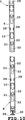
第10図は、垂直支柱の破断正面図である。
第11図は、垂直支柱の破断側面図である。
第12図は、垂直支柱の上面図である。
第13図は、垂直支柱の底端部の破断斜視図であり、足部材を示している。
第14図は、ビームの破断側面図である。
第15図は、ビームの破断上面図である。
第16図は、ビームの側面図である。
第17図は、データトラフの破断正面図である。
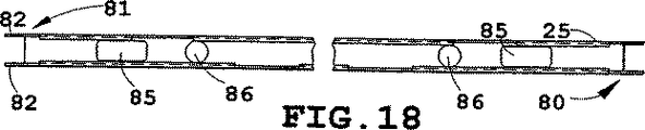
第18図は、データトラフの破断上面図である。
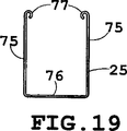
第19図は、データトラフの側面図である。
第20図は、電力トラフの破断正面図である。
第21図は、電力トラフの破断上面図である。
第22図は、電力トラフの側面図である。
第23図は、垂直支柱の破断上面図であり、カバーパネルがカバー取り付け開口に係合したところを示している。
第24図は、カバーパネルの破断斜視図であり、カバー保持クリップの取り付け方を示している。
第25図は、ベースカバーおよび取り付けタブを示す破断斜視図である。
第26図は、組み立て状態にある組立式可搬型間仕切りの破断側面図であり、上部キャップをデータトラフに取り付けたところを示している。
第27図は、端部カバーおよび垂直終端支柱を示す破断斜視図である。
第27A図は、終端上部キャップおよび上部キャップの破断斜視図である。
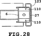
第28図は、端部カバーを取り付けた終端支柱の破断上面図である。
第28A図は、高さ変更形端部カバーを取り付けた終端支柱の破断上面図である。
第29図は、カバーパネルを前面に取り付け、電力トラフを両側面に取り付けた垂直中間支柱である。
第30図は、L字形支柱およびカバーの破断上面図である。
第30A図は、L字形カバーの破断斜視図である。
第30B図は、L字形上部キャップの斜視図である。
第31図は、T字形支柱およびカバーの破断上面図である。
第31A図は、T字形カバーの破断斜視図である。
第31B図は、T字形上部キャップの斜視図である。
第32図は、X字形支柱の破断上面図である。
第33図は、データおよび電力線およびコンセントを示す間仕切りシステムの破断分解斜視図である。
第34図は、ベースおよび腰の高さにデータコネクタおよび電力レセプタクルを示す1つのパネル部分の斜視図である。
好適な実施例の詳細な説明
本説明において、「上側」、「下側」、「右側」、「左側」、「後部」、「前部」、「垂直」、「水平」およびそれらの派生語は、第1図の向きに置いた本発明に関するものである。しかし、本発明は、特記しない限り、様々な変更向きにおよび段階順序を取ることもできることを理解されたい。また、添付の図面に示されており、以下の明細書で説明する特定の装置および方法は、添付の請求の範囲で定められた発明的概念の実施例にすぎないことも理解されたい。従って、ここに開示されている実施例に関する特定の寸法および他の物理的特徴は、請求の範囲に特記されていない限り、制限的に考えられるべきものではない。
参照番号1(第1図)は、本発明を具現した組立式可搬型間仕切りシステム全体を示している。図示の組立式可搬型間仕切りシステム1は、第3図に全体的に参照番号3で示されている中央部分3を有するパネルフレーム2(第2図および第3図)を備えている。少なくとも1つのカバーパネル4がパネルフレーム2の中央部分3の少なくとも一部を覆っている。コネクタ5がカバーパネル4をパネルフレーム2に取り外し式に取り付けて、パネルフレーム2に対するカバーパネル4の組み付けおよび取り外しを容易にしている。パネルフレーム2は、少なくとも2本の垂直結合部、例えば垂直支柱6を備えており、その各々は上端部7、下端部および対向面9を有しており、少なくとも2つのビーム連結ポート10が対応支柱6の上下端部7、8に近接した位置に設けられている。上下バーまたはビーム11が垂直支柱の上下端部7、8に近接した位置で垂直支柱6の間にほぼ水平方向に延在して、それらを連結ポート10に近接した位置で連結している。可動ロックウェッジ12が支柱6およびビーム11の一方の連結ポート10に近接した位置に配置されて、後退ロック解除位置13および延出ロック位置14間でシフトするようにそれに移動可能に取り付けられている。第4図および第5図に示されているように、ウェッジ係合表面15が支柱6およびビーム11の他方の連結ポート10に近接した位置に設けられて、ウェッジ12が延出ロック位置へシフトした時にウェッジ12に密着しまりばめ状態で係合することによって、支柱6およびビーム11を堅固であるが取り外し可能に連結して組立式可搬型間仕切り1の迅速で完全な組み立ておよび分解を行うことができるように配置されている。
図示の例では、本発明の可動ロックウェッジ12は、ウェッジ12が延出ロック位置14にシフトした時にウェッジ係合表面15に係合してそれを非弾性変形させる迅速脱着式コネクタを形成して、支柱6およびビーム11を堅固であるが取り外し可能に連結する密着しまりばめ(第5図)を生じる。また、各支柱6は垂直面17に沿って延在する垂直スロット列16を有している。第4図および第6図に示されているように、垂直スロット列16は、バインダ戸棚18または作業面19などの吊り付属ユニットを取り外し可能に取り付けるために設けられている。下側ファイル保管ユニット20も、支柱6の垂直スロット列16によって取り外し可能に支持されている(第1図)。従って、各支柱6は吊り付属ユニットを支持できる十分な構造強さを有している。
第2図ないし第4図に示されているように、各垂直支柱6は複数のユーティリティトラフポート21を有しており、データまたは通信線23や電力線24などのユーティリティ導管を通すための対応の窓22(第8図)が支柱6に貫設されている(第3図)。間仕切りは、ユーティリティ導管を収容して保持できる形状のデータトラフ25または電力トラフ26などの少なくとも1つのユーティリティトラフを備えている。ユーティリティトラフの両端部は、パネルフレーム2が組み立て状態にある時に支柱6の水平方向に整合した1対のユーティリティトラフポート21に取り外し可能に連結される形状を有している。
第9図に最もわかりやすく示されているように、2つの隣接した剛直なパネルフレーム2は、3本の垂直支柱6と、その上下端部7、8に近接した位置で支柱6間にほぼ水平に延在する少なくとも4本のビーム11とで構成されている。ビーム11は、支柱6間の主要連結構造部材であり、カバーパネル4が防音および装飾的機能を与えている。
第10図ないし第13図に示されているように、各垂直支柱6は1対の対向面9と前面27とを有している。各支柱6は、パネルフレーム2の上縁部31に沿ってデータ線23などのユーティリティ導管を敷設するために上側に沿って開放した窓を有する上部ユーティリティトラフポート29を有している。また、各支柱6は下端部に近接した位置にユーティリティトラフポート21を有しており、パネルフレーム2の下縁部32に沿って電力線24などのユーティリティ導管を敷設するために開放した下縁部を有する窓30(第25図)が設けられている(第3図)。各ユーティリティトラフポート21は、円形窓22と矩形窓33とを有している。データまたは電力トラフ25、26内に敷設されているデータおよび電力線23、24は窓22を通ることができる。必要ならば、電源ボックス63を電力トラフ26の底部にスナップ式にはめて(第3図)、電力線24を矩形窓33に通すことができる。第8図に示されているように、各ビーム連結ポート10は、4つの垂直スロット34と1つの水平スロット35とを有している。また、1対の上部スロット28(第10図)がビーム連結ポート10のすぐ上方に設けられて、高さ位置の変更時に短いパネルフレーム2の上部ユーティリティトラフを連結できるようにしている。ビーム連結ポート10の小さい窓36が下向きに延出したタブ37を有しており、それの下縁部に沿ってウェッジ係合表面15が設けられている。また、各支柱6の前面27に、カバーパネル4を取り付けるための開口38が設けられている。各支柱6は、支柱の下端部8に溶接されたねじ付きプレート40にはめ込まれた単一の垂直方向に調節可能な足部材39を備えている。前面27はさらに、ベースカバー42を取り外し可能に取り付けるために各支柱の下端部8付近に4つの開口41を有している。各支柱6は、それぞれ板金製の大きいU字形部材43と小さいU字形部材44とで形成されている。大小のU字形部材43、44は縁部45で互いに溶接されている。
第2図ないし第6図に示されているように、可動ロックウェッジ12が各ビーム11の上側47にリベット46で回転可能に取り付けられている。ビーム11は、ビーム連結ポート10の垂直スロット34にはまる下向きのフック48を各端部に形成する4つのタブおよびスロットを有している。各フック48は、各垂直スロット34の底縁部49に係合するスロット50を形成している。ロックウェッジ12は板金製であり、人が工具を使用することなくロックウェッジ12を後退ロック解除位置から延出ロック位置へ手でシフトさせることができるようにする機械的利点を与えるレバーアームを形成する平坦な本体部分53を有している。上向きに曲がったフランジ51が、ロックウェッジ12を第4図および第5図に示されている矢印Aと反対の方向に手で回転させて係合位置から外すために施工者が押しつける表面を形成している。各ロックウェッジ12はさらに、ロックウェッジ12が第5図に示されている延出ロック位置へ回転した時のストッパになる下向きフランジ52を有している。
ロックウェッジ12が延出ロック位置にシフトすると、ロックウェッジ12とウェッジ係合表面15との間の密着しまりばめによって下向き延出タブ37のウェッジ係合表面15が非弾性変形する。延出部分54は、ウェッジ係合表面15に係合しやすくするために121で「コイニング」すなわち平坦化されている。図示の例では、ウェッジ係合表面15は永久的すなわち非弾性変形するが、非弾性変形を生じない密着しまりばめを使用してビーム11を支柱6にロックすることもできる。あるいは、ロックウェッジ12の延出部分54にテーパ状カム表面を設けて、ウェッジ係合表面15に徐々に係合することによって密着しまりばめを生じることもできる。このしまりばめは、ウェッジ係合表面15が第5図および第6図に示されているものと同様に非弾性変形するように選択してもよい。
各ビーム11は、第3図に示されているデータトラフ25と同様にして、分解されているパネルフレームに隣接した組み立てパネルフレーム2を形成している1対の支柱6の間から取り外されるように構成されている。これは、ビーム11の第1端部56に長い延出フック48(第14図)を設けることによって行われる。さらに、第1端部56に水平タブ55が設けられている(第14図ないし第16図)。ビーム11は、矢印B(第14図)の方向に移動させてから、第2端部57を矢印Cの方向に持ち上げ、ビーム11を矢印Bと反対の方向に滑らせることによって取り外される。水平タブは、矢印Bの方向に移動させる時に安定性を与えると共にビーム11の第1端部56を案内するが、ビームを下方に移動させて垂直スロット34にはめ込む時には水平スロット35に係合しない。各ビーム11は、縁部60付近で互いに溶接した上側U字形部材58および下側U字形部材59で形成されている(第16図)。また、データまたは電力線23、24をパネルフレーム2の内部にビーム11を貫通して垂直方向に敷設するために、各ビーム11に矩形窓62および円形窓122が貫設されている。各ロックウェッジ12には、製造工程の塗装の際にロックウェッジ12を吊り下げるために使用される開口61が設けられている。
データおよび電力線23、24を通すために2種類のユーティリティトラフを用いることができる。データトラフ25が第17図ないし第19図に示されており、電力トラフ26が第20図ないし第22図に示されている。いずれのトラフもデータまたは電力線23、24の敷設に使用できるが、電力トラフ26だけはその下方に電源ボックス63および電力線24を吊り下げるために使用できる。
第17図ないし第19図に示されているように、各データトラフ25は、底壁76と下向きにカールした上縁部77を設けた側壁76とを含むU字形の断面を有している。各データトラフ25はさらに、第1端部80に下向きに延出したフックを形成する1対のタブ78およびスロット79を有している。データトラフ25は、第2端部81に1対のタブ82を有しており、パネルフレーム2が組み立て状態(第3図)にある時に1対の支柱6の間で行われるデータトラフ25の取り外しおよび取り付け時にデータトラフの第1端部80を矢印E(第17図)の方向に上向きに傾斜させる時のクリアランスを与えるカットバック部分83を備えている。各データトラフ25は、データコネクタ65を取り付けるための切り欠き部分84と、データおよび電力線23、24をパネルフレーム2内に垂直に敷設するための矩形開口85および円形開口86とを有している。
第20図ないし第22図に示されているように、概して各電力トラフ26は断面がU字形であり、データコネクタ65(第3図)を取り付けるための切り欠き部分66が側壁67に沿って設けられている。電力トラフ26の各端部は、ユーティリティトラフポート21(第4図)のL字形スロット72および水平スロット73にそれぞれはまる2つのL字形タブ69および1つの水平タブ70(第8図)を有している。電力トラフ26の一端部は、電力トラフ26をユーティリティトラフポート21にはめ込んだ後に第20図の矢印Dの方向に移動する滑りウェッジ71などのロックウェッジを有して、これによって電力線をコンセント64に差し込む時のユーティリティトラフ26の移動を防止する密着しまりばめを生じる。あるいは、電力トラフ26を支柱6に取り付けるためにロックウェッジ12を用いることもできる。細長いスロット74で図3に示されているように電源ボックス63をスナップ式に取り付けることができる。
第3図にわかりやすく示されているように、データトラフ25は、第2端部81を支柱6のユーティリティトラフポートに挿入することによって取り付けることができる。第1端部80を下向きに回転させてから、ビームを第1端部80の方に、さらに矢印E(第17図)と反対に下方へ移動させることによって、スロット79をユーティリティトラフポート21のL字形スロット72にはめ込む。第26図に示されているように、上部ユーティリティポート29の各々は、テーパ状上縁部138と垂直ノッチ部分139とを有している。上部データトラフ25を取り付ける時、タブ78および82をテーパ状縁部138に沿って下向きに押して、垂直ノッチ部分139にスナップ式にはめ込む。電力トラフ26も同様に、L字形タブ69および水平タブ70をユーティリティトラフポート21(第8図)の対応のL字形スロット72および水平スロット73に差し込むことによって取り付けることができる。次に、第2端部88を下向きに回転させて、ユーティリティトラフを第2端部88の方に移動させることによって、L字形タブ69および水平タブ70をユーティリティトラフポート21の対応のL字形スロット72および水平スロット73にはめ込む。次に、滑りウェッジ71を第20図に矢印Dで示されている方向にシフトさせる。
第23図および第24図を参照しながら説明すると、各カバーパネル4は、92で「トグルロック」された水平部材90および垂直部材91を含むカバーフレーム89を備えている。クリップ93がタブ95と、小突起すなわち屈曲部分96と、アーム94とを備えている。クリップ93は、第24図に矢印Fで示されている方向にタブ95を開口97に挿入することによってカバーフレーム89に取り付けられる。次に、クリップ93を矢印Gの方向に滑らせる。これによって、小突起すなわち屈曲部分96が開口97間の表面98に係合して、クリップが矢印Gと反対の方向に移動することが阻止される。第4図および第23図に示されているように、各クリップ93のアーム94が、垂直支柱6の開口38の外側部分98にはまる。開口38が隣接するカバー4を互いに間隔を置いて位置決めすることによって、垂直スロット列16のための隙間が設けられる。また、開口38がカバー4を支持することによって、カバー4は所定位置に固定されて垂直に移動しない。各カバー4は外側の装飾的な布層99と、ガラス繊維マットまたは他の適当な材料で形成できる厚い防音層100とを有している。
第25図に示されているように、各ベースカバー42は板金製であり、上側フランジ101および下側フランジ102を有している。上側フランジ101の各端部の上側タブ103が開口41にスナップ式にはまり、下側タブ104が開口41に係合することによって、ベースカバー42が支柱6に保持される。上側フランジ101に沿った切り欠き部分105が、データまたは電力線23、24の垂直敷設用の隙間を設けている。
第26図に示されているように、ポリマー材料で成形された上部キャップ106は、下向きに延出した1対の脚部107を有しており、その脚部の弓形部分108がデータトラフ26の下向きにカールした上縁部77にスナップ式にはまる。
第27図、第28図および第28A図を参照しながら説明すると、高さ変更形端部カバー109にスロット付きタブ110が設けられており、これらが垂直スロット列16の最上位置のスロットにはまることによって、支柱6用の装飾カバーを付けることができる。スロット付きタブ110をはめた後、端部カバー109の下端部126を支柱6の下端部8上で滑らせて、狭い部分125を支柱6に摩擦係合させる。端部カバー109にブレース124が設けられ、これが端部カバー109を偏位させてデータおよび電力線23および24用の垂直通路128を形成している。終端カバー123は、支柱6に内側表面127で当接している点を除いて、高さ変更形端部カバー109と同様である。
第29図ないし第32図を参照しながら説明すると、間仕切りシステム1は、直列形または終端支柱6(第29図)、L字形支柱112(第30図)、T字形支柱113(第31図)およびX字形支柱111(第32図)を含むことができる。中間または終端支柱6は、端部カバー109を設ける終端位置か、第29図に示されているような中間位置に使用することができる。第27A図に示されているように、終端上部キャップ135はポリマー材料で形成されており、上部キャップ106のノッチ領域133にはめ込まれる一体形クリップ134を備えている。高さ変更形上部キャップ(図示せず)は、高さ変更形端部カバー109(第28A図)の広幅に合わせるために若干長くなっている点を除いて、終端上部キャップ135と同じである。第30図および第30A図に示されているように、各L字形支柱は、L字形支柱112のスロット116に係合するフック115を有するL字形用カバー114によって覆うことができる。各L字形用カバー114は、垂直スロット列16に係合してその下端部を保持する小タブ130(第30A図)を備えている。ブレース129がL字形用カバー114の上下端部に剛性を与えている。L字形用カバー114は、電力線の垂直敷設に使用できる開放垂直通路117を形成している。第30B図に示されているように、L字形用上部キャップはポリマー材料で形成されており、上部キャップ106(第26図)のノッチ領域133にはめ込まれる一体形クリップ134を備えている。カバー4およびL字形用カバー114の間のスペースが、吊りバインダ戸棚または他の付属物を垂直スロット列16から吊り下げることができるようにする隙間を与えている。
T字形支柱113は窪み部分120を備え、それはT字形用カバー118と協働して、電力または通信線の垂直敷設用の垂直通路119(第31図)を形成している。T字形用カバー118は、垂直スロット列16に係合する上側フック131および下側フック132を有している。第31B図に示されているように、T字形用上部キャップ136は、上部キャップ106のノッチ領域133にはめ込まれる一体形クリップ134を備えている。
第32図に示されているように、X字形支柱111は、4つのパネルフレーム2をX字形状に連結するほぼX字形平面形状を有している。すべての支柱構造は単一の足部材39を有しており、さらに直線配列支柱6と同一構造の複数のビーム連結ポート10およびユーティリティトラフポート21を備えて向き合った表面を有している。また、各支柱は、吊り付属ユニットを支持するための垂直スロット列16を備えている。
第33図に示されているように、データおよび電力トラフ25および26は、データおよび電力線23および24やコンセント64およびデータコネクタ65を支持するための、組み立てが簡単で融通性のあるシステムを提供している。データおよび電力線23、24はユーティリティトラフおよびビームの開口を垂直方向に通ることができる。第34図に示されているように、腰の高さに取り付けられた単一の電力トラフをコンセント64およびデータコネクタ65の両方に用いることもできる。また、ベースカバー42を切り欠いて、パネルの底部にコンセント64およびデータコネクタ65の両方に用いている。
本発明の組立式可搬型間仕切りシステム1は、広範囲の電力および通信ケーブル要件を処理することができる、融通性があって運搬および組み立てが容易なシステムを提供している。パネルフレーム2は簡単であって迅速に組み立てられるが、バインダ戸棚18、作業面19および下側ファイル保管ユニット20などの吊り付属物を支持できる十分な構造強さを与える。各支柱は、支持用に単一の足部材を用いるため、パネルフレーム2の垂直方向調整が簡単になる。隣接のパネルフレーム2が組み立て状態にある間に、1対の垂直支柱6の間からビーム11やデータおよび電力トラフ25、26をすべて取り外してもよい。カバーパネル4は取り外しおよび取り付けが容易であり、防音および吸音層を形成する。
以上に記載した本発明の好適な実施例に対して、添付の請求の範囲で定められる本発明の精神または範囲から逸脱することなく様々な変更を加えることができることは、当該技術の専門家には明らかであろう。Background of the Invention
The present invention relates to an office partition panel system, and more particularly to a prefabricated portable partition having a unique post and beam structure configured to be quickly and easily manually assembled in the field.
In particular, as building costs continue to rise, there is an increasing interest in the effective use of building floor space. Open office plans have been developed to reduce overall office costs, which are generally modular and can be easily reconfigured to meet the changing needs of individual users as well as the diverse requirements of different tenants. A large open floor space with a furniture system is built into the building. One commonly used structure for creating an open plan is a mobile or portable partition panel that is removably interconnected to divide the open space into separate work units and / or offices. I have. Such partition panels are strong enough to support suspended furniture units such as work surfaces, overhead cabinets, shelves, etc., and are generally known as “system furniture” in the office furniture industry. Moreover, such a partition panel has a soundproofing and sound absorbing structure in order to promote a quiet and comfortable working environment.
Many partition panel systems have been developed to divide the office work space into smaller areas. A partition panel system as disclosed in U.S. Pat. No. 4,996,811 is a prefabricated rectangular partition panel with an integral rigid peripheral frame formed of top, bottom and end channels welded together. The member is used. A decorative cover panel is secured to both sides of the peripheral frame. Each peripheral frame member is rectangular and is often manufactured and transported as an integral part, and the decorative cover panel is often fixed to the frame. In installation, the prefabricated peripheral frame of each panel member is fixed to the peripheral frame of the adjacent panel member directly along their vertical edges or by a separate fixing column. Two height-adjustable leg portions or glide are provided along the lower edge of each partition panel member, one at a position proximate to each vertical panel edge. Since there are two vertical frame members at each panel joint, there is structural overlap in this type of panel structure. Also, each glide must be adjusted to an appropriate height, and this construction requires that both glide be adjusted at each panel joint during assembly. Furthermore, in general, the longer the panel, the lower the cost per unit length, but the longer the panel, the more difficult it is to handle, so there are practical dimensions for the partition panel members that can be transported and installed as an off-the-shelf unit. There is a limit.
Another partition panel system, such as that disclosed in US Pat. No. 5,150,554, uses a prefabricated rectangular partition panel member having an integral peripheral frame that is attached to a strut member along each vertical panel edge. ing. This type of structure has one glide on each post, but at least two vertical structural members at each connection between the panel and the post. This type of system has an overlapping structure, since only one vertical member is required to provide support and height adjustment. Moreover, since the rectangular partition panel member is manufactured and transported as an integral part, the size of the partition panel member that can be used is limited.
Another office split system, such as that disclosed in US Pat. No. 5,406,760, uses vertical posts and horizontal beams to attach each post along the vertical edge adjacent to the adjacent post. Since each strut is directly attached to an adjacent strut, this structure also has overlapping vertical structural members and glide.
Other office splitting devices, such as those disclosed in US Pat. Nos. 5,287,666 and 5,219,406, have multiple struts and beams, with a pair of beams on adjacent struts. A connector member to be attached is provided. This structure has two horizontal beams in a side-by-side relationship at each height position and directly unites two vertical columns in either a back-to-back or side-by-side relationship. For this reason, there is an overlap in both the strut and the beam structure. In addition, a connector member is necessary to attach the beam to the support column.
Summary of the Invention
One aspect of the present invention is a prefabricated portable partition with a panel frame having a central portion. The partition includes at least one cover panel that covers at least a part of the central portion of the panel frame. A connector removably attaches the cover panel to the panel frame to facilitate assembly and removal of the cover panel from the panel frame. The panel frame has at least two vertical struts having an upper end, a lower end, and both side surfaces. At positions close to the upper and lower ends of the column, at least two beam connection ports are provided on both side surfaces. The panel frame further has upper and lower beams extending in a substantially horizontal direction between the vertical columns at positions close to the upper and lower ends of the vertical columns. The upper and lower beams connect the vertical struts at positions close to the connection port. The panel frame further has a movable lock wedge located proximate to one of the support ports and the connection port of the beam. The movable lock wedge is movably attached so as to shift between the reverse lock release position and the extension lock position. The panel frame further has a wedge engaging surface provided proximate to the post and the other connection port of the beam. The wedge-engaging surface provides a solid but releasable connection of the struts and beams by engaging the wedges in close-fitting engagement when the wedges are shifted to the extended lock position, thereby assembling a portable partition Arranged for quick and complete assembly and disassembly.
According to another aspect of the present invention, in the portable partition system, each has an upper end portion, a lower end portion, and an opposing surface, and at least two beam connection ports are provided at positions close to the upper and lower end portions of the column. It is an improvement of a prefabricated frame structure with a vertical column of books. The frame structure includes upper and lower beams extending in a substantially horizontal direction between the vertical columns at positions close to the upper and lower ends of the vertical columns and connecting the vertical columns at a position close to the connection port. The frame structure further comprises a movable locking wedge disposed proximate to one of the strut and beam connection ports and movably attached thereto for shifting between a retracted unlocked position and an extended locked position. ing. The frame structure further includes a wedge engaging surface provided proximate to the post and the other connection port of the beam. The wedge-engaging surface provides a solid but releasable connection of the struts and beams by engaging the wedges in close-fitting engagement when the wedges are shifted to the extended lock position, thereby assembling a portable partition Arranged for quick and complete assembly and disassembly.
Yet another aspect of the present invention is a prefabricated portable type comprising at least two vertical struts, each having a plurality of utility trough ports, through which corresponding windows for the utility conduits pass. It is a partition. This partition is equipped with upper and lower beams, both ends of which connect vertical struts in close proximity to the upper and lower portions to form a rigid panel frame having a substantially open interior when in an assembled state. Form. The partition also has at least one cover panel that is shaped to enclose at least a portion of the open interior of the panel frame and is removably attached to the panel frame to allow easy access to the open interior. Yes. The partition further comprises at least one utility trough shaped to receive and hold the utility conduit, the ends of which are a pair of horizontally aligned struts when the panel frame is in the assembled state. It is configured to be removably coupled to the utility trough port.
A further aspect of the invention is a prefabricated portable partition system having at least three vertical columns with upper and lower ends and a vertical surface. The column has a sufficient structural strength to support the suspended attachment unit. The support column has a vertical slot row that extends along one vertical plane and can suspend a suspension accessory unit, and a beam connection port provided on another vertical plane. The partition system further comprises at least four beams extending substantially horizontally between the struts close to the upper and lower ends of the struts, both ends of which are rigidly connected to the beam connection port. When in the assembled state, each forms at least two adjacent rigid panel frames having a substantially open interior. The beam is the main structural connection between the columns. The partition system further comprises at least one cover panel shaped to surround at least a portion of at least one interior of the panel frame. The cover panel is removably attached to one panel frame to allow easy access to its open interior. The partition system further comprises a suspension attachment unit that is removably attached to at least one of the vertical slot rows of one selected end strut.
According to a further aspect of the present invention, in the portable partition system, at least two beams each having an upper end portion, a lower end portion and both side surfaces are provided at positions close to the upper and lower end portions of the column. It is an improvement of the assembly-type frame structure provided with the vertical support. The frame structure includes upper and lower beams extending in a substantially horizontal direction between the vertical columns at positions close to the upper and lower ends of the vertical columns and connecting the vertical columns at a position close to the connection port. The frame structure further includes a quick-removable connector positioned proximate to the post connection port. The frame structure further includes a second quick disconnect connector located proximate to the beam connection port, the second quick disconnect connector engaging the first quick disconnect connector to And the beam is arranged so that it can be firmly but removably connected for quick and complete assembly and disassembly of the prefabricated portable partition.
A further aspect of the present invention is an improvement in a quick-removable frame connection system having at least one strut and at least one beam in a portable partition system. The frame connection system includes at least one connection port disposed between the strut and the beam. At least one locking wedge is provided in a position proximate to one of the strut and beam connection ports and is movably attached thereto for shifting between a retracted unlocked position and an extended locked position. The frame connection system further comprises at least one wedge engaging surface at a location proximate to the post and the other connection port of the beam. When the wedge is shifted to the extended lock position, the wedge engages the wedge and is thereby inelastically deformed and tightly engages the post and the beam by closely engaging the wedge and engaging the wedge. Are arranged to be removably connected.
A first object of the present invention is to provide an assembly-type portable partition system. Accordingly, the present invention provides a partition that is variable and easy to assemble and disassemble with reduced complexity and fewer parts. Individual parts are assembled at the installation site, thus reducing transportation costs and allowing long and economical panel dimensions. Partition panels are easily and quickly assembled and do not require separate fasteners such as conventional nuts and bolts. The partition panel has sufficient structural strength to support the hanging accessory units such as a binder cupboard, a shelf, and a work surface. Utility troughs can be installed at various heights between struts for electrical and communication conduits. Utility troughs can be installed and removed after the structural beam is installed between adjacent struts. Each strut has a single adjustable foot member and a vertical row of slots for supporting the suspension attachment unit. A cover panel can be attached to close the open interior of the panel. In each series panel coupling portion, two adjacent cover panels are attached to one column.
The above and other features, objects and advantages of the present invention will become apparent upon reading the following description with reference to the accompanying drawings.
[Brief description of the drawings]
FIG. 1 is a perspective view of a prefabricated partition system embodying the present invention having struts and beam structures covered with soundproof decorative cover panels.
FIG. 2 is an exploded perspective view of the vertical column, beam and cover panel.
FIG. 3 is an exploded perspective view of the vertical strut, data and power trough, beam and cover panel.
FIG. 4 is a cutaway perspective view of the wedge lock and beam connection port.
FIG. 5 is a broken perspective view of the lock wedge in the engaged position, showing inelastic deformation of the wedge engaging surface.
FIG. 6 is a cutaway front view of the lock wedge in the engaged position, showing the deformation of the wedge engaging surface.
FIG. 7 is a partial schematic side view of a partition system provided with a hanging cupboard and a work surface.
FIG. 8 is a cutaway perspective view of a utility trough port and a power trough with a sliding wedge.
FIG. 9 is a cutaway perspective view of two adjacent panel frames, showing the intermediate strut with beams secured to opposite sides.
FIG. 10 is a cutaway front view of a vertical column.
FIG. 11 is a cutaway side view of a vertical column.
FIG. 12 is a top view of the vertical column.
FIG. 13 is a cutaway perspective view of the bottom end portion of the vertical column and shows the foot member.
FIG. 14 is a broken side view of the beam.
FIG. 15 is a broken top view of the beam.
FIG. 16 is a side view of the beam.
FIG. 17 is a cutaway front view of the data trough.
FIG. 18 is a broken top view of the data trough.
FIG. 19 is a side view of the data trough.
FIG. 20 is a cutaway front view of the power trough.
FIG. 21 is a cutaway top view of the power trough.
FIG. 22 is a side view of the power trough.
FIG. 23 is a cutaway top view of the vertical strut, showing the cover panel engaged with the cover mounting opening.
FIG. 24 is a cutaway perspective view of the cover panel and shows how to attach the cover holding clip.
FIG. 25 is a cutaway perspective view showing a base cover and mounting tabs.
FIG. 26 is a cutaway side view of the assembly-type portable partition in the assembled state, and shows the top cap attached to the data trough.
FIG. 27 is a cutaway perspective view showing the end cover and the vertical termination post.
FIG. 27A is a cutaway perspective view of a terminal upper cap and an upper cap.
FIG. 28 is a cutaway top view of the end strut with the end cover attached.
FIG. 28A is a cutaway top view of the end strut with a height-changing end cover attached.
FIG. 29 shows a vertical intermediate strut with a cover panel attached to the front and power troughs attached to both sides.
FIG. 30 is a cutaway top view of the L-shaped support column and cover.
FIG. 30A is a cutaway perspective view of an L-shaped cover.
FIG. 30B is a perspective view of an L-shaped upper cap.
FIG. 31 is a cutaway top view of the T-shaped support column and cover.
FIG. 31A is a cutaway perspective view of a T-shaped cover.
FIG. 31B is a perspective view of a T-shaped upper cap.
FIG. 32 is a cutaway top view of the X-shaped column.
FIG. 33 is an exploded perspective view of the partition system showing data, power lines and outlets.
FIG. 34 is a perspective view of one panel portion showing the data connector and power receptacle at the base and waist level.
Detailed Description of the Preferred Embodiment
In this description, “upper side”, “lower side”, “right side”, “left side”, “rear part”, “front part”, “vertical”, “horizontal” and their derivatives are in the direction of FIG. It relates to the present invention. However, it should be understood that the invention may be modified in various ways and in a step order unless otherwise specified. It is also to be understood that the specific devices and methods illustrated in the accompanying drawings and described in the following specification are merely examples of the inventive concepts defined in the appended claims. Accordingly, the specific dimensions and other physical characteristics relating to the embodiments disclosed herein are not to be considered as limiting unless otherwise specified in the claims.
Reference numeral 1 (FIG. 1) shows an entire assembly-type portable partition system embodying the present invention. The illustrated assembling
In the illustrated example, the
As shown in FIGS. 2-4, each
As can be seen most clearly in FIG. 9, two adjacent rigid panel frames 2 are approximately spaced between the three
As shown in FIGS. 10 to 13, each
As shown in FIGS. 2 to 6, the
When the
Each
Two types of utility troughs can be used to pass data and
As shown in FIGS. 17-19, each
As shown in FIGS. 20-22, each
As clearly shown in FIG. 3, the
Referring to FIGS. 23 and 24, each
As shown in FIG. 25, each
As shown in FIG. 26, the
Referring to FIGS. 27, 28, and 28A, the height-changing
Referring to FIGS. 29 to 32, the
The T-shaped
As shown in FIG. 32, the
As shown in FIG. 33, data and
The assembled
It will be appreciated by those skilled in the art that various modifications can be made to the preferred embodiments of the present invention described above without departing from the spirit or scope of the present invention as defined in the appended claims. Will be clear.
Claims (18)
該パネルフレームの中央部分の少なくとも一部を覆う少なくとも1つのカバーパネルと、
前記パネルフレームに対する前記カバーパネルの組み付けおよび取り外しを容易にするために前記カバーパネルを前記パネルフレームに取り外し可能に取り付けるコネクタとを備えた組立式可搬型間仕切りであって、
前記パネルフレームは、
各々が上端部、下端部および対向面を有し、少なくとも2つのビーム連結ポートを前記対向面上で且つ前記上下端部に近接した位置に設けている少なくとも2本の垂直支柱と、
該垂直支柱の前記上下端部に近接した位置で前記垂直支柱の間にほぼ水平方向に延在して、前記垂直支柱を前記連結ポートに近接した位置で堅固に連結する上下ビームと、
前記ビームの前記ビーム連結ポートに近接した位置に配置されて、ロック解除位置およびロック位置間でシフトするように垂直軸線回りに回転可能に取り付けられると共に延出部分を有する可動ロック部材と、
前記ビーム連結ポートに設けられたロック部材係合表面と
を備え、
各ビーム連結ポートは、少なくとも一対の垂直スロットと一つの開口部とを有すると共に、前記開口部の水平方向の縁部により前記ロック部材係合表面が形成され、
前記ビームの各端部は、下向きに延出した少なくとも一対のフックを有し、
前記ビームの少なくとも一対のフックを前記垂直支柱のビーム連結ポートの少なくとも一対の垂直スロットに係合させて前記ロック部材を前記ロック解除位置から前記ロック位置へシフトした時に前記ロック部材の延出部分が前記ロック部材係合表面に接して係合することによって、前記支柱および前記ビームを堅固であるが取り外し可能に連結して迅速で完全な組み立ておよび分解を行うことができるように配置されている組立式可搬型間仕切り。A rigid panel frame having a central portion;
At least one cover panel covering at least a portion of a central portion of the panel frame;
An assembly-type portable partition comprising a connector for detachably attaching the cover panel to the panel frame to facilitate assembly and removal of the cover panel from the panel frame;
The panel frame is
Each having an upper end portion, a lower end portion and an opposing surface, and at least two vertical support columns provided with at least two beam connection ports on the opposing surface and in the vicinity of the upper and lower end portions;
An upper and lower beam extending substantially horizontally between the vertical struts at a position close to the upper and lower ends of the vertical struts, and firmly connecting the vertical struts at a position close to the connection port;
It said beam wherein is disposed at a position close to the beam connecting port, and the movable locking member having an extending portion with rotatably mounted about a vertical axis so as to shift between the unlocked position and the locked position,
A locking member engaging surface provided on the beam connection port,
Each beam connection port has at least a pair of vertical slots and one opening, and the locking member engaging surface is formed by a horizontal edge of the opening,
Each end of the beam has at least a pair of hooks extending downward;
Extending portion of the locking member when the at least one pair of hooks at least shifted pair of said locking member is engaged with the vertical slots from the unlocking position to the locking position of the beam connecting ports of said vertical columns of said beam Assemblies arranged to engage the abutment surface of the locking member so that the struts and the beam are firmly but removably connected for quick and complete assembly and disassembly. Type portable partition.
前記ビームの各端部は、前記2対の垂直スロットにそれぞれ係合する2対のフックを有する請求項1〜3のいずれか一項に記載の間仕切り。The beam connection port has two pairs of vertical slots ;
The partition according to any one of claims 1 to 3 , wherein each end portion of the beam has two pairs of hooks respectively engaged with the two pairs of vertical slots .
ユーティリティ導管を収容して保持する少なくとも1つのユーティリティトラフを備えており、その両端部は前記支柱の水平方向に整合した1対の前記ユーティリティトラフポートに取り外し可能に連結される請求項6に記載の間仕切り。Each of the columns has a plurality of utility trough ports, and corresponding windows for passing utility conduits extend through the columns.
7. The utility trough of claim 6 , comprising at least one utility trough for receiving and holding a utility conduit, both ends of which are removably coupled to a pair of horizontally aligned utility trough ports of the struts. Partition.
前記上端部に近接した前記ユーティリティトラフポートは、ユーティリティ導管を前記パネルフレームの前記上縁部に沿って敷設するために開放上側を有する窓を含む請求項9に記載の間仕切り。The panel frame has an upper edge;
The divider of claim 9 , wherein the utility trough port proximate the upper end includes a window having an open upper side for laying a utility conduit along the upper edge of the panel frame.
前記下端部に近接した前記ユーティリティトラフポートは、ユーティリティ導管を前記下縁部に沿って敷設するために開放下側を有する窓を含む請求項10に記載の間仕切り。The panel frame has a lower edge;
11. The divider of claim 10 , wherein the utility trough port proximate the lower end includes a window having an open lower side for laying a utility conduit along the lower edge.
前記パネルフレームは、
前記支柱および前記電力トラフの一方の前記ユーティリティトラフ連結ポートに近接した位置に配置されて、ロック解除位置およびロック位置間でシフトするようにそれに移動可能に取り付けられている第2の可動ロック部材と、
前記支柱および前記電力トラフの他方の前記ユーティリティトラフ連結ポートに近接した位置に設けられた第2のロック部材係合表面とを備えており、該第2のロック部材係合表面は、前記第2のロック部材が前記ロック位置へシフトした時に前記ロック部材に密着しまりばめ状態で係合することによって、前記支柱および前記電力トラフを堅固であるが取り外し可能に連結して迅速な組み立ておよび分解を行うことができるように配置されている請求項7に記載の間仕切り。The utility trough forms a power trough,
The panel frame is
A second movable lock member disposed at a position proximate to the utility trough connection port of one of the strut and the power trough and movably attached thereto so as to shift between an unlock position and a lock position; ,
Provided with said strut and a second locking member engagement surface which is provided at a position close to the other of the utility troughs connection port of the power trough, said second locking member engagement surface, the second When the lock member is shifted to the lock position, the strut and the power trough are firmly but detachably connected to each other for quick assembly and disassembly by engaging the lock member in close contact with the lock member. 8. A partition as claimed in claim 7 , arranged so that it can be performed.
前記支柱の該垂直スロット列の少なくとも1つに取り外し可能に取り付けられた吊り付属ユニットを有している請求項17に記載の間仕切り。The column has a sufficient structural strength to support the suspension accessory unit, and a vertical slot row extends along the front surface so that the suspension accessory unit can be suspended.
18. A partition as claimed in claim 17 , comprising a suspension attachment unit removably attached to at least one of said vertical slot rows of said struts.
Applications Claiming Priority (3)
| Application Number | Priority Date | Filing Date | Title |
|---|---|---|---|
| US08/856,995 | 1997-05-15 | ||
| US08/856,995 US5899035A (en) | 1997-05-15 | 1997-05-15 | Knock-down portable partition system |
| PCT/US1998/009380 WO1998051876A1 (en) | 1997-05-15 | 1998-05-08 | Knock-down portable partition system |
Publications (3)
| Publication Number | Publication Date |
|---|---|
| JP2001525027A JP2001525027A (en) | 2001-12-04 |
| JP2001525027A5 JP2001525027A5 (en) | 2005-12-02 |
| JP4050796B2 true JP4050796B2 (en) | 2008-02-20 |
Family
ID=25324920
Family Applications (1)
| Application Number | Title | Priority Date | Filing Date |
|---|---|---|---|
| JP54932198A Expired - Fee Related JP4050796B2 (en) | 1997-05-15 | 1998-05-08 | Assembly-type portable partition system |
Country Status (11)
| Country | Link |
|---|---|
| US (4) | US5899035A (en) |
| EP (1) | EP0990078A4 (en) |
| JP (1) | JP4050796B2 (en) |
| KR (1) | KR20010012549A (en) |
| AR (1) | AR012708A1 (en) |
| AU (1) | AU737123B2 (en) |
| BR (1) | BR9808792A (en) |
| CA (1) | CA2287232A1 (en) |
| CO (1) | CO4700351A1 (en) |
| TW (1) | TW415988B (en) |
| WO (1) | WO1998051876A1 (en) |
Families Citing this family (157)
| Publication number | Priority date | Publication date | Assignee | Title |
|---|---|---|---|---|
| US6223485B1 (en) | 1996-06-07 | 2001-05-01 | Herman Miller, Inc. | Wall panel system |
| US5806258A (en) * | 1996-06-07 | 1998-09-15 | Haworth, Inc. | Wall panel system |
| US6167665B1 (en) | 1996-06-07 | 2001-01-02 | Herman Miller, Inc. | Corner post for a wall panel system |
| US6341457B1 (en) * | 1996-06-07 | 2002-01-29 | Herman Miller, Inc. | Light seal assembly for a wall panel system |
| US6301846B1 (en) | 1996-12-24 | 2001-10-16 | Steelcase Development Inc. | Knock-down portable partition system |
| US5899035A (en) * | 1997-05-15 | 1999-05-04 | Steelcase, Inc. | Knock-down portable partition system |
| US6546684B2 (en) | 1998-04-15 | 2003-04-15 | Steelcase Development Corporation | Partition panel |
| US6910306B2 (en) * | 1996-12-24 | 2005-06-28 | Steelcase Development Corporation | Knock-down portable partition system |
| US6167664B1 (en) * | 1997-05-28 | 2001-01-02 | Knoll, Inc. | Hybrid office panel construction for a modular office furniture system |
| DE19739642C2 (en) * | 1997-09-10 | 1999-12-16 | Eisenmann Kg Maschbau | Wall for the cabin of a paint shop |
| US6039613A (en) * | 1997-11-13 | 2000-03-21 | Ron Francis | Barrier strip cover and barrier strip for power distribution panels |
| US6359217B1 (en) * | 1998-06-05 | 2002-03-19 | Trendway Corporation | Cabinet with electrical/data conduit routing capabilities |
| US6374548B1 (en) | 1998-06-05 | 2002-04-23 | Trendway Corporation | Column-based workspace definition system |
| US6282854B1 (en) | 1998-06-05 | 2001-09-04 | Trendway Corporation | Frame-based workplace system |
| US6223916B1 (en) * | 1998-07-03 | 2001-05-01 | Barry M. Enos | Shelving crossbar retainer and assembly and method for fixing a crossbar to a post |
| US6230459B1 (en) * | 1998-12-04 | 2001-05-15 | Steelcase Development Inc. | Wall start for panel systems |
| US6659295B1 (en) | 1999-03-26 | 2003-12-09 | L&P Property Management Company | Adjustable shelving/display system |
| FI991064A (en) * | 1999-05-10 | 2000-11-11 | System 300 Group | Bowling alley structure |
| GB2353541B (en) | 1999-06-04 | 2003-10-15 | Miller Herman Inc | Stackable wall panel system |
| US6295764B1 (en) | 1999-06-04 | 2001-10-02 | Herman Miller, Inc. | Stackable wall panel system |
| US6349516B1 (en) | 1999-06-04 | 2002-02-26 | Haworth, Inc. | Frame arrangement for a wall panel system |
| US6256941B1 (en) * | 1999-06-04 | 2001-07-10 | Haworth, Inc. | Pad for panel |
| US6351917B1 (en) * | 1999-07-30 | 2002-03-05 | Steelcase Development Corporation | Stacking connector for partitions |
| US6161709A (en) * | 1999-08-13 | 2000-12-19 | John Sterling Corporation | Suspended shelf mounting system |
| US6253509B1 (en) * | 1999-08-13 | 2001-07-03 | Teknion Furniture Systems Limited | Workspace partition system |
| US6817147B1 (en) | 1999-12-30 | 2004-11-16 | Steelcase Development Corporation | Clip for panel trim |
| US6499608B1 (en) * | 2000-02-14 | 2002-12-31 | John Sterling Corporation | Wall-mounted storage system |
| US6948691B2 (en) | 2000-03-17 | 2005-09-27 | Jonathan Manufacturing Corporation | Computer server mounting apparatus |
| US6408579B1 (en) | 2000-04-25 | 2002-06-25 | Steelcase Development Corporation | Thin panel beam |
| AU2396502A (en) * | 2000-06-12 | 2002-02-05 | Vitra Patente Ag | Modular functional wall |
| US6397534B1 (en) * | 2000-06-12 | 2002-06-04 | Steelcase Development Corporation | Cover member lock for partition panels |
| IT1317354B1 (en) * | 2000-07-19 | 2003-06-16 | Marchioro Spa | PLANTER STRUCTURE. |
| EP1199418A1 (en) * | 2000-10-19 | 2002-04-24 | Details (Société Anonyme) | Modular vertical partition wall for adjacent working spaces |
| US7210270B1 (en) * | 2000-10-20 | 2007-05-01 | Steelcase Development Corporation | Partition system with elevated raceway |
| EP1207606A1 (en) * | 2000-11-20 | 2002-05-22 | Lk A/S | A method of providing an installation duct and a construction set for performing the method |
| EP1207607A1 (en) * | 2000-11-20 | 2002-05-22 | Lk A/S | A building system for providing walls with concealed ducts |
| WO2002059844A2 (en) * | 2001-01-26 | 2002-08-01 | Visual Graphic Systems Inc. | Facade vending machines |
| US6729085B2 (en) | 2001-02-09 | 2004-05-04 | Herman Miller, Inc. | Wall panel system |
| US6530490B1 (en) | 2001-03-15 | 2003-03-11 | Kma Licensing, Inc. | Reconfigurable retail merchandising system |
| MXPA03010846A (en) * | 2001-05-07 | 2004-11-22 | L & P Property Management Co | Modular room system and method. |
| US6739463B2 (en) * | 2001-05-25 | 2004-05-25 | L&P Property Management Company | Modular rack conversion apparatus and method |
| US6591563B2 (en) * | 2001-06-15 | 2003-07-15 | Steelcase Development Corporation | Panel system |
| EP1395717A1 (en) | 2001-06-15 | 2004-03-10 | Kimball International Inc. | Floor-to-ceiling wall panel system |
| US20030051415A1 (en) * | 2001-06-16 | 2003-03-20 | Matt Remelts | Accessories for a workspace |
| US20030094124A1 (en) * | 2001-11-20 | 2003-05-22 | Wishart Andrew S. | Modular pallet display system |
| KR100602376B1 (en) * | 2001-12-28 | 2006-07-14 | 오알지 주식회사 | Manufacturing method of partition frame post |
| US6722096B2 (en) | 2002-01-23 | 2004-04-20 | Quanex Corporation | Frame assembly and frame component for tensioning fabric about a panel of a partition system |
| US6684929B2 (en) | 2002-02-15 | 2004-02-03 | Steelcase Development Corporation | Panel system |
| US6748710B2 (en) | 2002-03-29 | 2004-06-15 | Steelcase Development Corporation | Partition trim having functional aspects |
| US6807776B2 (en) | 2002-03-29 | 2004-10-26 | Steelcase Development Corporation | Building outfitting system with common accessory-mounting feature |
| US6605776B1 (en) * | 2002-05-29 | 2003-08-12 | Dekko Engineering, Inc. | Mounting assembly for an electrical distribution block in modular office furniture |
| US8393122B2 (en) * | 2002-06-06 | 2013-03-12 | Kimball International, Inc. | Partition system |
| US20050034378A1 (en) * | 2002-06-06 | 2005-02-17 | Underwood Robert A. | Partition system |
| CN1659344A (en) * | 2002-06-06 | 2005-08-24 | 金波国际公司 | Partition system |
| KR20040046287A (en) * | 2002-11-26 | 2004-06-05 | 어난숙 | Assemble type partition |
| US6865853B2 (en) * | 2003-01-31 | 2005-03-15 | Hon Technology Inc. | Base assembly for wall panel construction |
| US20070042638A1 (en) * | 2003-04-14 | 2007-02-22 | Choi Cheon S | Prefabricating rack frame |
| CA2526769A1 (en) * | 2003-05-30 | 2005-01-06 | Herman Miller, Inc. | Work space management system |
| US20060000187A1 (en) * | 2004-06-10 | 2006-01-05 | Steelcase Development Corporation | Wood skin construction for partitions |
| AU2004203819A1 (en) * | 2004-08-11 | 2006-03-02 | JCB Communications Pty Ltd | Rack and Duct System |
| CA2516083C (en) | 2004-08-17 | 2013-03-12 | Dirtt Environmental Solutions Ltd. | Integrated reconfigurable wall system |
| USRE47132E1 (en) | 2004-08-17 | 2018-11-20 | Dirtt Environmental Solutions, Ltd | Integrated reconfigurable wall system |
| US7293666B2 (en) | 2004-11-17 | 2007-11-13 | American Power Conversion Corporation | Equipment enclosure kit and assembly method |
| US7603821B2 (en) * | 2005-01-13 | 2009-10-20 | Steelcase Inc. | Partition panel system and method |
| WO2006096997A1 (en) * | 2005-03-18 | 2006-09-21 | 3088-7418 Quebec Inc. | Modular building structure |
| DE102005016969A1 (en) * | 2005-04-13 | 2006-10-19 | Wanzl Metallwarenfabrik Gmbh | Device for delimiting a room |
| US7464509B1 (en) * | 2005-07-15 | 2008-12-16 | Brown James C | Security wall |
| US7144184B1 (en) * | 2005-07-29 | 2006-12-05 | Enlight Corporation | Rotary-type fastening structure |
| CA2674646A1 (en) * | 2005-09-08 | 2008-05-08 | John C. Bilello | Amorphous metal film and process for applying same |
| US7249872B2 (en) * | 2005-10-06 | 2007-07-31 | Catalina Lighting Inc. | Method and system for displaying lighting fixtures |
| US7702629B2 (en) * | 2005-12-02 | 2010-04-20 | Exegy Incorporated | Method and device for high performance regular expression pattern matching |
| US20070262685A1 (en) * | 2006-01-06 | 2007-11-15 | Symbiote, Inc. | Post and beam furniture construction |
| US8234983B2 (en) * | 2006-01-06 | 2012-08-07 | Travis M Randolph | Post and beam furniture construction |
| US20070163190A1 (en) * | 2006-01-18 | 2007-07-19 | Steelcase Development Corporation | Partition panel covering attachment assembly |
| FR2899202B1 (en) * | 2006-04-04 | 2009-02-13 | Airbus France Sas | DEVICE AND METHOD FOR ELECTRICALLY GENERATING EMERGENCY ON BOARD AN AIRCRAFT |
| DE202006009860U1 (en) * | 2006-06-23 | 2006-08-24 | Doka Industrie Gmbh | Support frame for the vertical shuttering supports for concrete floors has open grip profiles and adjustable clamps |
| US7707795B2 (en) * | 2006-11-09 | 2010-05-04 | Haworth, Inc. | Wall panel with gusseted open frame |
| US7841142B2 (en) * | 2006-11-22 | 2010-11-30 | Steelcase Inc. | Stack-on panel assembly |
| US7661237B2 (en) * | 2006-12-11 | 2010-02-16 | Haworth, Ltd. | Skin attachment structure for wall system |
| GB2447896B (en) * | 2007-03-24 | 2011-12-07 | Glenn Williams | A Panel |
| EP1978169B1 (en) | 2007-04-06 | 2011-05-25 | Jean-Michel Carlier | Dwelling such as a house, in particular with a wooden frame or similar |
| FR2914662A1 (en) * | 2007-04-06 | 2008-10-10 | Jean Michel Carlier | Dwelling i.e. frame house, has prefabricated modules including inner frame for receiving facing to create service space with thickness equal to that of frame, where space receives pipes or wires of electrical installation |
| US8104850B2 (en) | 2007-05-30 | 2012-01-31 | Steelcase Inc. | Furniture storage unit |
| US8056235B1 (en) * | 2007-06-05 | 2011-11-15 | Master Coil, LLC | Process for producing a rail and post fence system |
| US7857267B2 (en) * | 2007-06-13 | 2010-12-28 | Alcatel Lucent | Unique mounting for computer equipment in frames |
| US7762411B2 (en) * | 2007-10-17 | 2010-07-27 | International Business Machines Corporation | Tool-less rack rail system incorporating clamping mechanism |
| AT506281B1 (en) * | 2008-01-14 | 2010-05-15 | Alexander Doronin | ARRANGEMENT FOR ROOM DISTRIBUTION |
| US8910435B2 (en) * | 2008-05-27 | 2014-12-16 | Steelcase Inc. | Partition assembly |
| DE102008026631B4 (en) * | 2008-06-04 | 2011-02-10 | Benteler Automobiltechnik Gmbh | Instrument carrier and method for its production |
| NZ571533A (en) * | 2008-09-24 | 2009-12-24 | Stahlton Engineered Concrete A | Hanger system for concrete building units |
| US8640391B2 (en) * | 2008-10-16 | 2014-02-04 | Hill-Rom Services, Inc. | Modular architectural room system |
| JP4944937B2 (en) * | 2008-12-25 | 2012-06-06 | 株式会社大気社 | Building assembly structure and building assembly method using the assembly structure |
| US8215081B2 (en) * | 2009-01-29 | 2012-07-10 | Krueger International, Inc. | Panel tile and top cap retention system |
| WO2010092563A1 (en) * | 2009-02-12 | 2010-08-19 | Kingspan Holdings (Irl) Limited | A framing system |
| US8939421B1 (en) * | 2009-03-23 | 2015-01-27 | Process Retail Group, Inc. | Glide floor for merchandising and display of retail products |
| US8322750B2 (en) * | 2009-04-02 | 2012-12-04 | Ez Loader Custom Boat Trailers, Inc. | Trailer incorporating a beam structure |
| CA2668445C (en) * | 2009-06-05 | 2015-11-03 | Inscape Corporation | Office partition system |
| US8689511B2 (en) | 2009-08-31 | 2014-04-08 | Joseph C. Fleming, III | Method and system for interconnecting structural panels |
| US20110068073A1 (en) * | 2009-09-10 | 2011-03-24 | John Michael Hervey | Tool-less Metal Filler Panel for a Data Rack |
| US8656648B2 (en) * | 2009-10-29 | 2014-02-25 | Krueger International, Inc. | Panel system |
| US8549804B2 (en) | 2010-10-21 | 2013-10-08 | Kimball International, Inc. | Office partition electrical system |
| WO2012052530A1 (en) * | 2010-10-22 | 2012-04-26 | Syma Intercontinental Ag | Frame profile system |
| US9131622B2 (en) * | 2011-06-03 | 2015-09-08 | Middle Atlantic Products, Inc. | Rack rail locking lever |
| US8967054B2 (en) | 2011-06-03 | 2015-03-03 | Kimball International, Inc. | Office desking system |
| CA2796997C (en) | 2011-06-11 | 2016-05-10 | Dirtt Environmental Solutions, Ltd. | Modular wall nesting system |
| US8365479B2 (en) | 2011-06-17 | 2013-02-05 | Phat Energy Corporation | Solar power structure |
| US8561360B2 (en) * | 2011-07-26 | 2013-10-22 | Maxwell H. Corbin, Jr. | Sound arresting barrier |
| ITAR20110011U1 (en) * | 2011-08-01 | 2013-02-02 | Nedo Magrini | FURNISHING COMPONENT, PARTICULARLY OF THE SHELF, LIBRARY OR THE LIKE |
| GB201113574D0 (en) * | 2011-08-05 | 2011-09-21 | Keystone Lintels Ltd | A panel and a method for building panels |
| EP2736382A4 (en) | 2011-12-28 | 2015-03-04 | Dirtt Environmental Solutions | Modular walls incorporating recessed, extendable furniture |
| US20130168335A1 (en) * | 2012-01-04 | 2013-07-04 | Peerless Industries, Inc. | Moveable fixture for exhibiting display devices or the like |
| US8826613B1 (en) * | 2012-02-29 | 2014-09-09 | David J Chrien | Utility trench system components |
| US20130291300A1 (en) * | 2012-05-07 | 2013-11-07 | Invacare Corporation | Frame latching assemblies |
| US9169640B2 (en) | 2012-06-08 | 2015-10-27 | Steelcase Inc. | Frameless glass mounting system |
| FR2993585B1 (en) | 2012-07-20 | 2014-08-01 | Legrand France | METHOD FOR MOUNTING A HOLLOW WINDOW |
| CN103582376A (en) * | 2012-08-07 | 2014-02-12 | 鸿富锦精密工业(武汉)有限公司 | Electronic device frame |
| US9427083B2 (en) * | 2012-12-06 | 2016-08-30 | Herman Miller, Inc. | Furniture docking system |
| CN103906401A (en) * | 2012-12-26 | 2014-07-02 | 鸿富锦精密工业(武汉)有限公司 | Electronic device framework |
| US10017935B2 (en) | 2013-03-28 | 2018-07-10 | David A. Corden | Quick attachment system for modular construction |
| US8997413B2 (en) * | 2013-08-15 | 2015-04-07 | Extraordinary Offerings, Ltd. | Modular booth system |
| EP2859812B1 (en) * | 2013-10-09 | 2019-01-09 | Evans Consoles Corporation | Console furniture and features thereof |
| US10301821B2 (en) | 2014-02-20 | 2019-05-28 | DIRTT Environmental Solutions., Ltd. | Reconfigurable wall system |
| CN104389365B (en) * | 2014-11-26 | 2018-11-13 | 上海优格装潢有限公司 | Link mechanism for screen-separated system |
| CN107567673B (en) * | 2015-01-09 | 2019-11-26 | 欧光欧洲有限公司 | Modular wall wall system and panel component for such system |
| US10136546B2 (en) * | 2015-12-30 | 2018-11-20 | Stephen Skidmore | Portable tool and method for temporarily supporting electronic equipment on a rack |
| CA2932533C (en) | 2016-02-10 | 2023-10-03 | Dirtt Environmental Solutions, Ltd. | Modular walls with embedded furniture and opposing feature |
| EP3322863A4 (en) | 2016-06-10 | 2019-05-01 | DIRTT Environmental Solutions, Ltd. | Glass substrates with touchscreen technology |
| WO2017214425A1 (en) | 2016-06-10 | 2017-12-14 | Dirtt Environmental Solutions, Inc. | Wall system with electronic device mounting assembly |
| CA3030282A1 (en) | 2016-07-08 | 2018-01-11 | Dirtt Environmental Solutions, Inc. | Low-voltage smart glass |
| USD785374S1 (en) | 2016-08-15 | 2017-05-02 | Prospect Furniture LLC | Collaborative workspace |
| WO2018058229A1 (en) * | 2016-09-27 | 2018-04-05 | Иностранное Общество С Ограниченной Ответственностью "Цмо" | Equipment fastening system |
| US10975898B2 (en) * | 2016-11-14 | 2021-04-13 | Joseph C. Fleming, III | Method and system for interconnecting structural panels |
| ES2673108B1 (en) * | 2016-12-16 | 2019-03-26 | Hernan Cases Xavier | SYSTEM OF PANELS OF COVERING WITH INTEGRATED SERVICES |
| US10405657B2 (en) | 2017-05-17 | 2019-09-10 | Knoll, Inc. | Bracket mechanism for pre-fabricated office enclosure beams and method of using the same |
| CA3006818C (en) * | 2017-05-31 | 2021-02-16 | Meadow Burke, Llc | Connector for precast concrete structures |
| DE102017112423A1 (en) | 2017-06-06 | 2018-12-06 | elva-tec Radeberger Reinraumsysteme GmbH | wall system |
| US10626602B2 (en) * | 2017-06-12 | 2020-04-21 | Herman Miller, Inc. | Workstation |
| WO2019030553A1 (en) * | 2017-08-10 | 2019-02-14 | Glenn Sloss | Adjustable architectural frame system |
| US10098460B1 (en) * | 2017-08-23 | 2018-10-16 | Clairson, Inc. | Shelf brackets, hang rod brackets, and storage systems including the same |
| US11242690B2 (en) | 2018-01-19 | 2022-02-08 | Titcomb Brothers Manufacturing, Inc. | Loop tie for concrete forming panel systems |
| CA3088405A1 (en) | 2018-01-19 | 2019-07-25 | Titcomb Brothers Manufacturing, Inc. | Loop tie for concrete forming panel systems |
| US11002027B2 (en) * | 2018-01-19 | 2021-05-11 | Titcomb Brothers Manufacturing, Inc. | Stacking clip for concrete forming panel systems |
| USD914916S1 (en) * | 2018-02-01 | 2021-03-30 | Oldcastle Buildingenvelope, Inc. | Face cover assembly |
| US10697183B1 (en) * | 2018-07-06 | 2020-06-30 | Associated Architectural Products, Inc. | Method and apparatus for a wall panel system |
| US10368639B1 (en) * | 2018-07-09 | 2019-08-06 | Shenter Enterprise Co., Ltd. | Butt-joining and positioning structure of vertical bar with hook hole |
| MX2021004752A (en) * | 2018-10-26 | 2021-08-24 | Poppin Inc | Power rail system. |
| US11191178B2 (en) | 2019-01-24 | 2021-11-30 | Steelcase Inc. | Display support system and method for the use thereof |
| DE102019105794A1 (en) * | 2019-03-07 | 2020-09-10 | kubix Gesellschaft für Entwicklung und Produktion temporärer Bauten mbH | Wall construction, in particular for trade fair or museum construction, and method for setting up the wall construction |
| US11608634B2 (en) * | 2019-05-03 | 2023-03-21 | Watson Furniture Group, Inc. | Flexible workspace partition system |
| USD979376S1 (en) | 2020-01-09 | 2023-02-28 | Meadow Burke, Llc | Enclosed structural support |
| US11492797B2 (en) | 2020-03-05 | 2022-11-08 | Meadow Burke, Llc | Connector for precast concrete structures |
| US11717097B2 (en) * | 2020-05-22 | 2023-08-08 | American Business Forms, Inc. | Moveable base for retail gondola |
| WO2022020136A1 (en) | 2020-07-23 | 2022-01-27 | Steelcase Inc. | Display support system and method for the use thereof |
| KR102474700B1 (en) * | 2020-11-24 | 2022-12-05 | 코오롱글로벌 주식회사 | Versatile system wall structure |
| AU2022305073A1 (en) * | 2021-07-01 | 2024-01-25 | Zipwall, Llc. | Support system |
| CN113882557B (en) * | 2021-11-22 | 2022-07-15 | 浙江易家建筑工程有限公司 | High-strength steel plate shear wall |
| CN116445523A (en) * | 2023-04-10 | 2023-07-18 | 西北农林科技大学 | Wheat stress resistance gene TaBSL3 and application thereof |
Family Cites Families (107)
| Publication number | Priority date | Publication date | Assignee | Title |
|---|---|---|---|---|
| US2218426A (en) * | 1938-07-26 | 1940-10-15 | Jr William Griswold Hurlbert | Metal studding system |
| US2430654A (en) * | 1946-02-01 | 1947-11-11 | Clayton B Voege | Wall structure |
| US2963127A (en) * | 1957-12-24 | 1960-12-06 | Manville George Dewey | Variable length brace |
| US3209869A (en) * | 1961-09-12 | 1965-10-05 | Andrew B Hammitt | Partition assembly |
| US3462892A (en) * | 1968-01-22 | 1969-08-26 | Ronald K Meyer | Adapter wall |
| US3492766A (en) * | 1968-05-09 | 1970-02-03 | Mccloskey Grant Corp | Adjustable stud |
| US3601432A (en) * | 1969-05-15 | 1971-08-24 | Streater Ind Inc | Display fixture frame structure |
| US3638376A (en) * | 1970-01-05 | 1972-02-01 | Hough Mfg Corp | Portable partition |
| US3697034A (en) * | 1970-01-12 | 1972-10-10 | Irving W Shell | Locking shelf bracket support structure |
| US3713474A (en) * | 1971-04-26 | 1973-01-30 | J Orlando | Portable wall partition |
| BE767043A (en) * | 1971-05-12 | 1971-10-01 | Janssen Leopold M L | DOUBLE WALL PARTITION AND PARTITION ELEMENTS. |
| US3745732A (en) * | 1971-08-05 | 1973-07-17 | Superior Industries | Demountable partition system |
| US3789567A (en) * | 1972-12-29 | 1974-02-05 | American Standard Inc | Edge seals for multiple-interfitting partitions |
| US3858988A (en) * | 1973-02-07 | 1975-01-07 | Melvin Cohen | Joint structure |
| US3886698A (en) * | 1973-06-15 | 1975-06-03 | Hauserman Inc | Panel and structural units for wall assemblies |
| DE2415208A1 (en) * | 1974-03-29 | 1975-10-09 | Dustmann Dula Werk | KIT FOR A CONNECTION BETWEEN A SHELF POST AND A CROSS LINK |
| US3888440A (en) * | 1974-04-08 | 1975-06-10 | Unistrut Corp | Support arrangement |
| DE2425837A1 (en) * | 1974-05-28 | 1975-12-11 | Kesseboehmer Draht & Metall H | Shelving with extra safety fastening for horizontal panels - has clamping eccentric preventing upward and sideways movement of shelves |
| US4018019A (en) * | 1974-08-19 | 1977-04-19 | Hauserman, Inc. | Panel and structural units for wall assemblies |
| US3971182A (en) * | 1975-05-02 | 1976-07-27 | Gf Business Equipment, Inc. | Portable wall assembly |
| US4048768A (en) * | 1976-09-30 | 1977-09-20 | Harter Corporation | Device for lockably securing appurtenances to a decorative wall |
| CA1044870A (en) * | 1977-05-05 | 1978-12-26 | Reginald S. Price | Suspension assembly for partition panel |
| US4265502A (en) * | 1977-06-27 | 1981-05-05 | American Seating Company | Panel wall systems with modular component build-up |
| US4123879A (en) * | 1977-06-27 | 1978-11-07 | American Seating Company | Panel wall systems with modular component build-up |
| US4154419A (en) * | 1978-06-05 | 1979-05-15 | Harter Corporation | Shelf support bracket construction |
| US4224769A (en) * | 1978-06-12 | 1980-09-30 | Hauserman Limited | Space divider system |
| US4338990A (en) * | 1978-08-18 | 1982-07-13 | American Seating Company | Panel wall systems with modular component build-up |
| US4434596A (en) * | 1978-10-06 | 1984-03-06 | Hauserman, Inc. | Partition head assembly for partition wall panels |
| US4205815A (en) * | 1978-11-16 | 1980-06-03 | Roblin Industries, Inc. | Shelf bracket, shelf bracket-stud combination and shelf bracket-clip combination |
| US4249578A (en) * | 1979-05-29 | 1981-02-10 | Freeman James D | Length-adjustable stiffener for fiberboard ducts |
| US4448231A (en) * | 1979-06-11 | 1984-05-15 | Litton Business Systems, Inc. | Panel system edge sealing means |
| US4416093A (en) * | 1979-06-11 | 1983-11-22 | Litton Business Systems, Inc. | Panel system interconnecting means |
| US4771583A (en) * | 1979-10-03 | 1988-09-20 | Hauserman, Inc. | Space divider system |
| US4356672A (en) * | 1980-02-08 | 1982-11-02 | Vaughan Walls, Inc. | Partitioning system |
| US4314429A (en) * | 1980-02-20 | 1982-02-09 | Ernest Casteel | Siding holder |
| FR2508524A1 (en) * | 1981-06-25 | 1982-12-31 | Mors Jean Bouchon Entr Elect | MODULAR ASSEMBLY FOR CONSTRUCTING AN EXHIBITION LOCATION |
| US4391073A (en) * | 1980-12-12 | 1983-07-05 | Rosemount Office Systems, Inc. | Movable panel assembly |
| US4334374A (en) * | 1981-03-26 | 1982-06-15 | The Mead Corporation | Means for attaching a panel to an upright |
| US4406374A (en) * | 1981-08-12 | 1983-09-27 | Myco, Inc. | Locking device for display rack |
| GB2109500B (en) * | 1981-09-18 | 1986-01-15 | Worrallo A C | Framework joints |
| US4489530A (en) * | 1981-12-23 | 1984-12-25 | Chi Ming Chang | Sandwich wall structure and the method for constructing the same |
| US4535577A (en) * | 1982-12-15 | 1985-08-20 | Global Upholstery Company Limited | Office panelling system |
| AU572830B2 (en) * | 1983-04-19 | 1988-05-19 | Geoffrey Ballantyne Ashton | Sectional screens |
| FR2551809B1 (en) * | 1983-09-13 | 1987-01-30 | Duroyaume Philippe | PROFILE ASSEMBLY DEVICE |
| US4567698A (en) * | 1983-12-13 | 1986-02-04 | Knoll International, Inc. | Space divider system |
| US4625476A (en) * | 1983-12-27 | 1986-12-02 | Nihon Shuno System Kabushiki Kaisha | Partition wall |
| US4876835A (en) * | 1984-09-10 | 1989-10-31 | Herman Miller, Inc. | Work space management system |
| US4685255A (en) * | 1984-09-10 | 1987-08-11 | Herman Miller, Inc. | Work space management system |
| GB8510909D0 (en) | 1985-04-30 | 1985-06-05 | Vickers Plc | Office screens & partitions |
| US4682457A (en) * | 1985-08-15 | 1987-07-28 | Spencer Richard O | Open office landscape system |
| US4625477A (en) * | 1985-12-13 | 1986-12-02 | Masonite Corporation | Display wall formed of readily attachable and detachable panels |
| NZ214578A (en) * | 1985-12-16 | 1989-05-29 | Tube Fab Ltd | Partition wall construction |
| US4716699A (en) * | 1986-01-17 | 1988-01-05 | Rostec Industries | Wall panels with single load-bearing connector posts |
| FR2600726B2 (en) * | 1986-04-11 | 1988-11-10 | Chenel Guy | DEVICE FOR ASSEMBLING STAND FRAME FOR TEMPORARY EXPOSURE. |
| US4757657A (en) * | 1986-06-02 | 1988-07-19 | Architectural Wall Systems, Inc. | Floor-to-ceiling wall system |
| US4719731A (en) * | 1986-12-22 | 1988-01-19 | Gf Furniture Systems, Inc. | Post cover for partition systems |
| US4914873A (en) * | 1987-03-05 | 1990-04-10 | Herman Miller, Inc. | Work environment system |
| JPH0684643B2 (en) * | 1987-03-14 | 1994-10-26 | コクヨ株式会社 | Movable partition wall |
| US4858407A (en) * | 1987-05-01 | 1989-08-22 | Smolik Robert A | Lateral stabilizer for wall |
| US4918879A (en) * | 1987-05-29 | 1990-04-24 | Commercial And Architectural Products, Inc. | Merchandising wall structure including readily attachable and detachable panels and having plastic reveals |
| IT212259Z2 (en) * | 1987-07-06 | 1989-07-04 | Coop Operai Mobilieri | PARTITION WALL PARTICULARLY FOR OFFICES |
| IT1222449B (en) * | 1987-08-06 | 1990-09-05 | Coopsette Srl | INTERIOR DIVIDING WALL COMPONIBLE WITH FIRE-SHIELDING PROPERTIES AND SIMILAR |
| CH671614A5 (en) * | 1988-01-28 | 1989-09-15 | Mantel Embru Werke | |
| CH671597A5 (en) * | 1988-01-28 | 1989-09-15 | Mantel Embru Werke | |
| US4837988A (en) * | 1988-01-29 | 1989-06-13 | National Gypsum Company | Universal secondary stud |
| US5155960A (en) * | 1988-03-29 | 1992-10-20 | Indal Furniture Systems A Division Of Indal Limited | Cam action connector for joining furniture panels |
| US5211502A (en) * | 1988-08-08 | 1993-05-18 | Upham Hill Christopher W | Connection system |
| US5062246A (en) * | 1988-11-16 | 1991-11-05 | Sykes Christopher C | Partition structures and frame elements therefor |
| US4996811A (en) | 1988-11-23 | 1991-03-05 | The Shaw-Walker Company | Open office system partition panel assembly |
| US5065559A (en) * | 1988-12-16 | 1991-11-19 | Art Guild, Inc. | Wall system and method of construction |
| US4991368A (en) * | 1989-01-06 | 1991-02-12 | Amstore Corporation | Wall system |
| US4971281A (en) * | 1989-05-22 | 1990-11-20 | Hon Industries Inc. | Anti-dislodgement mechanism |
| US4991365A (en) * | 1989-06-09 | 1991-02-12 | Harter Corporation | Foot and leveling mechanism for panels in a relocatable wall |
| US4942713A (en) * | 1989-06-09 | 1990-07-24 | Harter Corporation | Interconnecting structure for releasably securing successive panels in a relocatable wall |
| US5054255A (en) * | 1989-10-27 | 1991-10-08 | Herbert Maninfior Design/Engineering | Wall panel construction and connection system |
| US5069263A (en) * | 1990-02-08 | 1991-12-03 | Hon Industries, Inc. | Panel interlock system |
| US5063715A (en) * | 1990-02-14 | 1991-11-12 | Herman Miller, Inc. | Wall system and equipment tile therefor |
| US5033526A (en) * | 1990-05-15 | 1991-07-23 | Westinghouse Electric Corp. | Office space dividing system |
| IT1240376B (en) * | 1990-05-21 | 1993-12-10 | C.O.M.S. Coop. A.R.L. | PROCEDURE FOR THE PRODUCTION OF OFFICE FURNITURE SYSTEMS AND OFFICE FURNITURE GROUP |
| US5079884A (en) * | 1990-06-04 | 1992-01-14 | National Gypsum Company | Extendible interconnected Z-studs |
| US5172530A (en) * | 1990-11-06 | 1992-12-22 | Allsteel Inc. | Sound attenuation panel arrangement with cabling accommodating capability for office furniture space divider systems |
| US5150554A (en) | 1990-12-19 | 1992-09-29 | Haworth, Inc. | Panel-post arrangement |
| US5209035A (en) * | 1991-01-10 | 1993-05-11 | Steelcase Inc. | Utility panel system |
| US5134826A (en) * | 1991-04-23 | 1992-08-04 | Precision Manufacturing, Inc. | Structural panel connector for space dividing system |
| US5214890A (en) * | 1991-04-29 | 1993-06-01 | Teknion Furniture Systems | Office panel with lay-in communication cable capability |
| US5177917A (en) * | 1991-12-02 | 1993-01-12 | Castillo Haucke J M Del | Modular panel wall structure |
| US5219406A (en) * | 1991-12-23 | 1993-06-15 | Schwartz Bros. Wood & Metal Furnitures Ltd. | Versatile modular office partitions |
| US5274970A (en) * | 1992-04-07 | 1994-01-04 | Roberts Raymond P | Freestanding partition system |
| US5277005A (en) * | 1992-05-04 | 1994-01-11 | Teknion Furniture Systems | Free-standing partitioning panel |
| US5241796A (en) * | 1992-05-04 | 1993-09-07 | Teknion Furniture Systems | Securing bracket |
| US5207336A (en) * | 1992-05-20 | 1993-05-04 | Core Technologies, Inc. | Support bar for storage rack |
| US5377466A (en) * | 1992-05-29 | 1995-01-03 | Haworth, Inc. | Separable post/panel system |
| US5383318A (en) * | 1992-11-04 | 1995-01-24 | Herman Miller, Inc. | Raceway cable retention and accommodation apparatus |
| US5464302A (en) * | 1993-08-23 | 1995-11-07 | National Gypsum Company | Extendible interconnected C-studs |
| CA2101190C (en) * | 1993-10-15 | 2005-03-15 | Hollanding Inc. | Modular office furniture partition |
| US5657606A (en) * | 1993-11-09 | 1997-08-19 | Ressel; Dennis Edward | Building system |
| AU681217B2 (en) | 1994-02-09 | 1997-08-21 | Thomas Mccracken Gilmore | Partition wall framing assembly for suspending gypsum board panels |
| DK35094A (en) * | 1994-03-28 | 1995-09-29 | Am System Silkeborg As | Inventory System |
| US5477971A (en) * | 1994-04-29 | 1995-12-26 | L&P Property Management Company | Gondola rack modular stacking system |
| US5606919A (en) * | 1995-06-07 | 1997-03-04 | Haworth, Inc. | Space-dividing fence for power and/or communication distribution |
| US5586593A (en) * | 1995-06-30 | 1996-12-24 | Hunt Holdings, Inc. | Partitioning system |
| US5657885A (en) * | 1995-09-07 | 1997-08-19 | E And E Specialties, Inc. | Display wall |
| US5600926A (en) * | 1995-10-31 | 1997-02-11 | Furniture Source International Inc. | Panel connecting arrangements |
| US5642593A (en) * | 1996-01-17 | 1997-07-01 | Shieh; Steven J. | Knockdown and reassemble office partition |
| IT242513Y1 (en) * | 1996-02-02 | 2001-06-14 | Gianfranco Zuffetti | TELESCOPIC UPRIGHT FOR REMOVABLE WALLS |
| US5685121A (en) * | 1996-02-16 | 1997-11-11 | Defrancesco; Frank | Metal stud |
| US5899035A (en) * | 1997-05-15 | 1999-05-04 | Steelcase, Inc. | Knock-down portable partition system |
-
1997
- 1997-05-15 US US08/856,995 patent/US5899035A/en not_active Expired - Lifetime
-
1998
- 1998-04-15 US US09/060,913 patent/US6098358A/en not_active Expired - Lifetime
- 1998-05-08 BR BR9808792-4A patent/BR9808792A/en not_active IP Right Cessation
- 1998-05-08 EP EP98921048A patent/EP0990078A4/en not_active Withdrawn
- 1998-05-08 AU AU73736/98A patent/AU737123B2/en not_active Expired
- 1998-05-08 JP JP54932198A patent/JP4050796B2/en not_active Expired - Fee Related
- 1998-05-08 CA CA002287232A patent/CA2287232A1/en not_active Abandoned
- 1998-05-08 TW TW087107105A patent/TW415988B/en not_active IP Right Cessation
- 1998-05-08 WO PCT/US1998/009380 patent/WO1998051876A1/en active Search and Examination
- 1998-05-08 KR KR1019997010504A patent/KR20010012549A/en not_active Application Discontinuation
- 1998-05-12 CO CO98026432A patent/CO4700351A1/en unknown
- 1998-05-15 AR ARP980102276A patent/AR012708A1/en active IP Right Grant
-
1999
- 1999-02-03 US US09/243,915 patent/US6079173A/en not_active Expired - Lifetime
-
2000
- 2000-04-21 US US09/558,753 patent/US6276103B1/en not_active Expired - Lifetime
Also Published As
| Publication number | Publication date |
|---|---|
| AR012708A1 (en) | 2000-11-08 |
| AU737123B2 (en) | 2001-08-09 |
| KR20010012549A (en) | 2001-02-15 |
| BR9808792A (en) | 2000-07-18 |
| EP0990078A4 (en) | 2003-04-02 |
| US6079173A (en) | 2000-06-27 |
| AU7373698A (en) | 1998-12-08 |
| WO1998051876A1 (en) | 1998-11-19 |
| CO4700351A1 (en) | 1998-12-29 |
| TW415988B (en) | 2000-12-21 |
| CA2287232A1 (en) | 1998-11-19 |
| US6276103B1 (en) | 2001-08-21 |
| US5899035A (en) | 1999-05-04 |
| JP2001525027A (en) | 2001-12-04 |
| US6098358A (en) | 2000-08-08 |
| EP0990078A1 (en) | 2000-04-05 |
Similar Documents
| Publication | Publication Date | Title |
|---|---|---|
| JP4050796B2 (en) | Assembly-type portable partition system | |
| US6301846B1 (en) | Knock-down portable partition system | |
| AU702876B2 (en) | Partition system | |
| US6330773B1 (en) | Stacking bracket for partitions | |
| US6112472A (en) | Integrated furniture system including overhead framework system and partition system | |
| US6052958A (en) | Wall panel system | |
| US6910306B2 (en) | Knock-down portable partition system | |
| US6684929B2 (en) | Panel system | |
| CA2343813C (en) | Knock-down panel partition system | |
| US6266935B1 (en) | Floor channel for partition system | |
| US6546684B2 (en) | Partition panel | |
| AU743710B2 (en) | Knock-down portable partition system | |
| MXPA97004467A (en) | Particle system | |
| US6230459B1 (en) | Wall start for panel systems | |
| US6178702B1 (en) | Flexible light seal for partition systems | |
| US6351917B1 (en) | Stacking connector for partitions | |
| AU766667B2 (en) | Knock-down portable partition system | |
| CA2539496C (en) | Knock-down panel partition system |
Legal Events
| Date | Code | Title | Description |
|---|---|---|---|
| A521 | Request for written amendment filed |
Free format text: JAPANESE INTERMEDIATE CODE: A523 Effective date: 20050408 |
|
| A621 | Written request for application examination |
Free format text: JAPANESE INTERMEDIATE CODE: A621 Effective date: 20050408 |
|
| A131 | Notification of reasons for refusal |
Free format text: JAPANESE INTERMEDIATE CODE: A131 Effective date: 20070403 |
|
| A601 | Written request for extension of time |
Free format text: JAPANESE INTERMEDIATE CODE: A601 Effective date: 20070703 |
|
| A602 | Written permission of extension of time |
Free format text: JAPANESE INTERMEDIATE CODE: A602 Effective date: 20070820 |
|
| A521 | Request for written amendment filed |
Free format text: JAPANESE INTERMEDIATE CODE: A523 Effective date: 20070803 |
|
| TRDD | Decision of grant or rejection written | ||
| A01 | Written decision to grant a patent or to grant a registration (utility model) |
Free format text: JAPANESE INTERMEDIATE CODE: A01 Effective date: 20071106 |
|
| A61 | First payment of annual fees (during grant procedure) |
Free format text: JAPANESE INTERMEDIATE CODE: A61 Effective date: 20071130 |
|
| R150 | Certificate of patent or registration of utility model |
Free format text: JAPANESE INTERMEDIATE CODE: R150 |
|
| FPAY | Renewal fee payment (event date is renewal date of database) |
Free format text: PAYMENT UNTIL: 20101207 Year of fee payment: 3 |
|
| FPAY | Renewal fee payment (event date is renewal date of database) |
Free format text: PAYMENT UNTIL: 20101207 Year of fee payment: 3 |
|
| FPAY | Renewal fee payment (event date is renewal date of database) |
Free format text: PAYMENT UNTIL: 20111207 Year of fee payment: 4 |
|
| FPAY | Renewal fee payment (event date is renewal date of database) |
Free format text: PAYMENT UNTIL: 20111207 Year of fee payment: 4 |
|
| FPAY | Renewal fee payment (event date is renewal date of database) |
Free format text: PAYMENT UNTIL: 20121207 Year of fee payment: 5 |
|
| FPAY | Renewal fee payment (event date is renewal date of database) |
Free format text: PAYMENT UNTIL: 20121207 Year of fee payment: 5 |
|
| FPAY | Renewal fee payment (event date is renewal date of database) |
Free format text: PAYMENT UNTIL: 20131207 Year of fee payment: 6 |
|
| R250 | Receipt of annual fees |
Free format text: JAPANESE INTERMEDIATE CODE: R250 |
|
| R250 | Receipt of annual fees |
Free format text: JAPANESE INTERMEDIATE CODE: R250 |
|
| R250 | Receipt of annual fees |
Free format text: JAPANESE INTERMEDIATE CODE: R250 |
|
| LAPS | Cancellation because of no payment of annual fees |