EP0216807B1 - Verfahren und mittel zur herstellung eines abgabegeräts für visköse und semi-visköse materialien - Google Patents
Verfahren und mittel zur herstellung eines abgabegeräts für visköse und semi-visköse materialien Download PDFInfo
- Publication number
- EP0216807B1 EP0216807B1 EP86901301A EP86901301A EP0216807B1 EP 0216807 B1 EP0216807 B1 EP 0216807B1 EP 86901301 A EP86901301 A EP 86901301A EP 86901301 A EP86901301 A EP 86901301A EP 0216807 B1 EP0216807 B1 EP 0216807B1
- Authority
- EP
- European Patent Office
- Prior art keywords
- core
- cavity
- die
- end wall
- cap
- Prior art date
- Legal status (The legal status is an assumption and is not a legal conclusion. Google has not performed a legal analysis and makes no representation as to the accuracy of the status listed.)
- Expired
Links
- 238000000034 method Methods 0.000 title claims abstract description 15
- 238000004519 manufacturing process Methods 0.000 title claims abstract description 10
- 239000011345 viscous material Substances 0.000 title claims description 6
- 238000000465 moulding Methods 0.000 claims abstract description 18
- 230000013011 mating Effects 0.000 claims abstract description 14
- 239000000463 material Substances 0.000 claims description 17
- 238000002347 injection Methods 0.000 claims description 8
- 239000007924 injection Substances 0.000 claims description 8
- 230000015572 biosynthetic process Effects 0.000 claims description 5
- 238000007789 sealing Methods 0.000 claims description 4
- 230000009969 flowable effect Effects 0.000 claims description 2
- 238000001746 injection moulding Methods 0.000 abstract description 8
- 229940034610 toothpaste Drugs 0.000 abstract description 4
- 239000000606 toothpaste Substances 0.000 abstract description 4
- 239000012528 membrane Substances 0.000 abstract 1
- 238000010276 construction Methods 0.000 description 5
- 238000011109 contamination Methods 0.000 description 2
- 239000012530 fluid Substances 0.000 description 2
- 230000001154 acute effect Effects 0.000 description 1
- 238000005452 bending Methods 0.000 description 1
- 238000006073 displacement reaction Methods 0.000 description 1
- 238000001125 extrusion Methods 0.000 description 1
- 238000012423 maintenance Methods 0.000 description 1
- 239000002184 metal Substances 0.000 description 1
- 230000001105 regulatory effect Effects 0.000 description 1
Images


Classifications
-
- B—PERFORMING OPERATIONS; TRANSPORTING
- B65—CONVEYING; PACKING; STORING; HANDLING THIN OR FILAMENTARY MATERIAL
- B65D—CONTAINERS FOR STORAGE OR TRANSPORT OF ARTICLES OR MATERIALS, e.g. BAGS, BARRELS, BOTTLES, BOXES, CANS, CARTONS, CRATES, DRUMS, JARS, TANKS, HOPPERS, FORWARDING CONTAINERS; ACCESSORIES, CLOSURES, OR FITTINGS THEREFOR; PACKAGING ELEMENTS; PACKAGES
- B65D47/00—Closures with filling and discharging, or with discharging, devices
- B65D47/04—Closures with discharging devices other than pumps
- B65D47/06—Closures with discharging devices other than pumps with pouring spouts or tubes; with discharge nozzles or passages
- B65D47/08—Closures with discharging devices other than pumps with pouring spouts or tubes; with discharge nozzles or passages having articulated or hinged closures
- B65D47/0804—Closures with discharging devices other than pumps with pouring spouts or tubes; with discharge nozzles or passages having articulated or hinged closures integrally formed with the base element provided with the spout or discharge passage
- B65D47/0833—Hinges without elastic bias
- B65D47/0838—Hinges without elastic bias located at an edge of the base element
- B65D47/0842—Hinges without elastic bias located at an edge of the base element consisting of a strap of flexible material
-
- B—PERFORMING OPERATIONS; TRANSPORTING
- B29—WORKING OF PLASTICS; WORKING OF SUBSTANCES IN A PLASTIC STATE IN GENERAL
- B29C—SHAPING OR JOINING OF PLASTICS; SHAPING OF MATERIAL IN A PLASTIC STATE, NOT OTHERWISE PROVIDED FOR; AFTER-TREATMENT OF THE SHAPED PRODUCTS, e.g. REPAIRING
- B29C45/00—Injection moulding, i.e. forcing the required volume of moulding material through a nozzle into a closed mould; Apparatus therefor
- B29C45/17—Component parts, details or accessories; Auxiliary operations
- B29C45/26—Moulds
- B29C45/36—Moulds having means for locating or centering cores
-
- B—PERFORMING OPERATIONS; TRANSPORTING
- B65—CONVEYING; PACKING; STORING; HANDLING THIN OR FILAMENTARY MATERIAL
- B65D—CONTAINERS FOR STORAGE OR TRANSPORT OF ARTICLES OR MATERIALS, e.g. BAGS, BARRELS, BOTTLES, BOXES, CANS, CARTONS, CRATES, DRUMS, JARS, TANKS, HOPPERS, FORWARDING CONTAINERS; ACCESSORIES, CLOSURES, OR FITTINGS THEREFOR; PACKAGING ELEMENTS; PACKAGES
- B65D35/00—Pliable tubular containers adapted to be permanently or temporarily deformed to expel contents, e.g. collapsible tubes for toothpaste or other plastic or semi-liquid material; Holders therefor
- B65D35/44—Closures
-
- B—PERFORMING OPERATIONS; TRANSPORTING
- B29—WORKING OF PLASTICS; WORKING OF SUBSTANCES IN A PLASTIC STATE IN GENERAL
- B29C—SHAPING OR JOINING OF PLASTICS; SHAPING OF MATERIAL IN A PLASTIC STATE, NOT OTHERWISE PROVIDED FOR; AFTER-TREATMENT OF THE SHAPED PRODUCTS, e.g. REPAIRING
- B29C45/00—Injection moulding, i.e. forcing the required volume of moulding material through a nozzle into a closed mould; Apparatus therefor
- B29C45/17—Component parts, details or accessories; Auxiliary operations
- B29C45/26—Moulds
- B29C45/36—Moulds having means for locating or centering cores
- B29C2045/363—Moulds having means for locating or centering cores using a movable core or core part
-
- B—PERFORMING OPERATIONS; TRANSPORTING
- B29—WORKING OF PLASTICS; WORKING OF SUBSTANCES IN A PLASTIC STATE IN GENERAL
- B29C—SHAPING OR JOINING OF PLASTICS; SHAPING OF MATERIAL IN A PLASTIC STATE, NOT OTHERWISE PROVIDED FOR; AFTER-TREATMENT OF THE SHAPED PRODUCTS, e.g. REPAIRING
- B29C45/00—Injection moulding, i.e. forcing the required volume of moulding material through a nozzle into a closed mould; Apparatus therefor
- B29C45/0053—Injection moulding, i.e. forcing the required volume of moulding material through a nozzle into a closed mould; Apparatus therefor combined with a final operation, e.g. shaping
- B29C45/006—Joining parts moulded in separate cavities
-
- B—PERFORMING OPERATIONS; TRANSPORTING
- B29—WORKING OF PLASTICS; WORKING OF SUBSTANCES IN A PLASTIC STATE IN GENERAL
- B29C—SHAPING OR JOINING OF PLASTICS; SHAPING OF MATERIAL IN A PLASTIC STATE, NOT OTHERWISE PROVIDED FOR; AFTER-TREATMENT OF THE SHAPED PRODUCTS, e.g. REPAIRING
- B29C45/00—Injection moulding, i.e. forcing the required volume of moulding material through a nozzle into a closed mould; Apparatus therefor
- B29C45/0081—Injection moulding, i.e. forcing the required volume of moulding material through a nozzle into a closed mould; Apparatus therefor of objects with parts connected by a thin section, e.g. hinge, tear line
-
- B—PERFORMING OPERATIONS; TRANSPORTING
- B29—WORKING OF PLASTICS; WORKING OF SUBSTANCES IN A PLASTIC STATE IN GENERAL
- B29L—INDEXING SCHEME ASSOCIATED WITH SUBCLASS B29C, RELATING TO PARTICULAR ARTICLES
- B29L2023/00—Tubular articles
- B29L2023/20—Flexible squeeze tubes, e.g. for cosmetics
-
- B—PERFORMING OPERATIONS; TRANSPORTING
- B29—WORKING OF PLASTICS; WORKING OF SUBSTANCES IN A PLASTIC STATE IN GENERAL
- B29L—INDEXING SCHEME ASSOCIATED WITH SUBCLASS B29C, RELATING TO PARTICULAR ARTICLES
- B29L2031/00—Other particular articles
- B29L2031/56—Stoppers or lids for bottles, jars, or the like, e.g. closures
- B29L2031/565—Stoppers or lids for bottles, jars, or the like, e.g. closures for containers
-
- B—PERFORMING OPERATIONS; TRANSPORTING
- B65—CONVEYING; PACKING; STORING; HANDLING THIN OR FILAMENTARY MATERIAL
- B65D—CONTAINERS FOR STORAGE OR TRANSPORT OF ARTICLES OR MATERIALS, e.g. BAGS, BARRELS, BOTTLES, BOXES, CANS, CARTONS, CRATES, DRUMS, JARS, TANKS, HOPPERS, FORWARDING CONTAINERS; ACCESSORIES, CLOSURES, OR FITTINGS THEREFOR; PACKAGING ELEMENTS; PACKAGES
- B65D2251/00—Details relating to container closures
- B65D2251/10—Details of hinged closures
- B65D2251/1016—Means for locking the closure in closed position
- B65D2251/105—The closure having a part fitting over the rim of the container or spout and retained by snapping over integral beads or projections
Definitions
- This invention relates to a method of and means for manufacture of a dispenser for viscous or semi-viscous material and in particular it relates to a dispenser of the type generally referred to in my earlier specification published under International Publication No. WO81/01544, of the 11th June, 1981 and based on Australian priority date of the 30th November, 1979.
- Swiss Patent Specification No. 451494 discloses the use of an elongated core with an axially moveable core locating member acting on the outer end thereof which member is engageable in a recess in the die and which is retractable during the final stages of the moulding operation.
- core shift is the maintenance of the core position as core shift or core bend, hereinafter included in the term "core shift", is known to occur and can result in uneven moulding and similar problems but it is one of the objects of the present invention to overcome this problem and to provide a method of and means for allowing moulding to be more effectively controlled to avoid core shift and similar problems.
- the method of manufacturing a dispenser for viscous or semi-viscous materials in which the dispenser is in the form of a tube having an end wall and, extending from the perimeter thereof a generally tubular wall adapted after filing to be closed at its other end, in which method an elongated core is projected in the hollow of a die and has its outer end stabilised by engaging an aligning face on the core with a mating aligning face on the die, plastic material is injected into the cavity defined between the core and the die to fill the cavity and the core is withdrawn from its engagement with the die while continuing the flow of the plastic material to complete the end wall between the core and the die whereby the part of the end wall surrounding the aligning faces and the wall of the tube is formed while the core is stabilised by the aligning faces and the formation of the end wall is completed when the aligning face on the core is withdrawn from the aligning face of the die, characterised by the steps of:
- a die and core assembly for the manufacture of a dispenser for viscous or semi-viscous materials in which a hollow in a die has projecting into it a core to form between them a tubular wall cavity and an end wall cavity, the tubular wall cavity extending from the perimeter of the end wall cavity to form the wall and end wall of an elongated hollow body of the dispenser, the core being adapted to be positioned in the die throughout the moulding operation to define the cavities, the assembly including an aligning face on the core sloping in relation to the axis of the core, a mating aligning face on the die adapted to engage the sloping aligning face on the core axially to align the core in the die during the initial moulding process to form the tube wall and the part of the end wall surrounding the aligning faces but being adapted to disengage during the final moulding process to complete the formation of the end wall, characterised by channels in the end of the core between a injection duct within the area defined by the mating aligning
- the invention is particularly adapted to form toothpaste tubes into which the material can be fed through the open end and the end then sealed, whereby the content is held against contamination or loss until removed through a nozzle at the closed end of the tube, but is not to be limited to this as it is advantageous wherever accurately formed an elongated tube having one end closed is to be formed, the invention ensuring that the core will not shift in the die during the heavy injection moulding stresses which would result in unsatisfactory non-uniform wall thickness of the body of the tube and also undesirable distribution of the material.
- the means for the manufacture of such a dispenser comprise an aligning face at the inner end portion of the core sloping in relation to the axis of the core, and a mating aligning face on the die arranged to engage the face on the core to axially align the core in the die when the core is positioned in the die, the die and core being arranged to have relative axial movement whereby to disengage the faces during a two part moulding process at which first stage the core is axially aligned with the cavity in the die by interengagement of the aligning faces but at the second stage of which the aligning faces are separated by the relative axial movement to extend the cavity across the end of the tube.
- the material from which the tube is to be formed is preferably injected into the space defined by the aligning faces and through channels into the cavity between the core and the die surrounding the faces.
- the invention is particularly adapted to form toothpaste tubes into which the material can be fed through the open end and the end then sealed, whereby the content is held against contamination or loss until removed through a nozzle at the closed other end of the tube, but is not to be limited to this use as it is advantageous wherever accurately formed an elongated tube having one end closed is to be formed, the invention ensuring that the core will not shift in the die during the heavy injection moulding stresses which would result in unsatisfactory nonuniform wall thicknesses of the body of the tube and also undesirable distribution of the material.
- the core has an axially movable section which carries the aligning face, this face could be formed on the core itself and the complete core moved axially in relation to the die. It is however generally convenient to have a smaller separately movable aligning member.
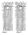
- the die 1 can be of any usual or approved construction, preferably built up of a number of metal layers in which the cavities are formed and provided with the necessary temperature regulating and flow means which are not specifically referred to herein as being within the ambit of persons versed in the art of injection moulding.
- the core 2 has in it an axially movable stem having at its inner end an aligning member 4 which has at its end an aligning face 5 adapted to engage a mating aligning face 6 in the die 1.
- the die 1 has in it a central duct 7 through which the moulding material is injected, and this duct opens into the space 8, see Fig. 3, defined by the aligning face 6 which face 6 is at the perimeter of a recess 9 in the die 1.
- the aligning member 4 has its end of truncated pyramidal form as shown particularly in Fig. 5 but can be in truncated conical form, the face 5 being formed on the end of the aligning member 4, the aligning member 4 being movable to cause the end to project to engage in the recess 9.
- the face of the aligning member 4 has in it a series of channels 11 which open to the injection duct 7 and serve to distribute the injection moulding material to the part of the end wall cavity 12 surrounding the aligning faces 5, 6 and formed between the hollow of the die 1 and the face of the core 2 and hence to the wall cavity 13.
- the flow control so achieved allows precise supply of the injection moulding material to all parts of the cavity, including the relatively small-dimensioned wall cavity 13 of the tube and through a hinge strap cavity to the cap cavity 15.
- the stem 3 is hollow and carries temperature control fluid or fluids to the aligning member 4.
- the die as will be seen defines with the end of the core 2 the end wall cavity 12 which opens to the wall cavity 13, and this end wall cavity 12 opens to a nozzle cavity 16.
- the cap cavity 15 opens to a seal cavity 17.
- a groove 18 is used to facilitate flow down the thin wall cavity 13.
- the means for moving the aligning member 4 through the stem 3 can take any usual or approved form and its operation can be computer timed to ensure a correct sequence, using pressure and/or temperature sensing if required.
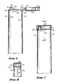
- the hinge strap cavity 14 has ends 19 from which the cavity is directed generally in the plane of the wall cavity 13 and the rim of the cap cavity 15 so that the curved generally semi-circular shape shown results whereby stress at the two ends of the strap is minimised.
- the arrangement allows the channels 11 which lead from the main injection duct 7 on the axis of the core 2 to be varied in size to encourage correct flow velocity in different directions and for instance this can ensure the extra flow to the cap cavity 15 through the hinge strap cavity 14.
- the end wall 20 formed in the end wall cavity 12 has the recess 9 formed in it which has inwardly sloping face 5 formed at its periphery, the wall 22 of the tube formed in the wall cavity 13 extending generally axially from the end wall 20. It is the length of this which causes core shift at the inner end of the moulding cavity, which shift is prevented by the arrangement described.
- the cap 23 is attached to the end wall 20 by the hinge strap 24 which is formed by flow through the hinge strap cavity 14, which hinge strap 24 is of relatively substantial dimension to ensure correct flow and is preferably of a length such and is curved when the cap is open so that the hinge part allows the cap to be moved readily away from its sealing position on the end of the tube during normal use.
- the cap feed can be enhanced by a channel bridging the strap 24.
- the hinge strap 24 folds into a recess 25 in the cap 23 when the cap 23 is swung over from its open and its moulding position into its closed position and because of the relative length of the curved hinge strap 24, while the hinge strap 24 is not visible as a projection when the tube is sealed allows a neat and highly effective construction to be achieved and allows the tube to be formed so that the cap 23 can lock into position by having an engaging rim 26 on it which engage a recess 27 in the periphery of the end wall 20 to form a lock sufficient to hold the cap 23 firmly in place but allowing the cap 23 to be opened when the content of the tube is to be ejected.
- the discharge nozzle 28 is positioned remotely of the hinge strap 24 and the cap 23 carries a sealing socket 29 which fits over the nozzle 28 and the socket 29 and nozzle 28 has circumferential undulations 30 so that when the pocket 29 is engaged on the nozzle 28 as the cap 23 is positioned in its closing location the cap 23 is guided into its final position and forms an effective seal not only of the outlet of the nozzle but of the whole of the area surrounding the nozzle to maintain hygenic conditions.
- the end wall has an outwardly extending guide member 31 adjacent to the hinge strap 24 which is adapted to engage a correspondingly shaped slit 32 on the cap 23 adjacent to the hinge strap 24 so that as the cap 23 is swung over and the hinge strap 24 is accommodated in the engaging slit 32 in the cap, the cap has that end firmly located by the upstanding guide member 31 to ensure that it readily engages the nozzle 28 and the periphery of the end wall 20 and this ensures that the cap 23 does not require holding means around its periphery adjacent to the hinge strap 24 but the holding means can be remote from this as the upstanding guide members 31 firmly locates the hinge end of the cap 23 against sideways displacement while at the other end the nozzle 28 forms the guide and also the holding means but acting in association with the shaped engaging rim 26 fitting into the recess 27 remotely of the hinge strap 24.
- the discharge nozzle 28 has a break-away end 34 which on being rotated fractures at 35 to open the nozzle 28.
- the groove 18 leaves longitudinal ridges 36 on the inner face of the wall 22.
- the described method and apparatus can be generally applied where a problem exists in maintaining a core in correct position in relation to a die and need not necessarily be limited to the formation of a tube as defined herein, the particular mating aligning members forming a highly advantageous form of flow control because when the two aligning faces are fully engaged the flow from the main injection channel is through channels radiating through the interengaging arrangement so that initially the injection in the various directions is closely controlled but before injection is completed relatively axial movement between the dies is effected so that the end of, for instance, a toothpaste tube, can be closed by the completion of an end wall of the tube as defined herein, which end closure 20 may have a sealed or open discharge nozzle.
- the hinge strap 24, as referred to earlier herein, is specially formed to be in the recess 25.
- the terminal portions 37 ensure that the bending stress is distributed over the cured part and not taken by acute angles and the ends.
- the portions 37 ensure that the hinge strap is stressed into the recess 25 where the cap 23 is closed onto the end closure 20.
Landscapes
- Engineering & Computer Science (AREA)
- Mechanical Engineering (AREA)
- Manufacturing & Machinery (AREA)
- Moulds For Moulding Plastics Or The Like (AREA)
- Diaphragms For Electromechanical Transducers (AREA)
- Fuel-Injection Apparatus (AREA)
- Telephone Function (AREA)
Claims (10)
- Verfahren zur Herstellung einer Abgabevorrichtung für viskose oder halbviskose Materialien, wobei die Abgabevorrichtung in Form eines Rohres (22) mit einer Stirnwand (20) vorliegt, von deren Umfang aus eine generell rohrförmige Wand verläuft, die nach Füllen an ihrem anderen Ende verschließbar ist,
wobei ein langgestreckter Kern (2) vorgesehen ist, der den Hohlraum einer Form (2) hineinragt und dessen äußeres Ende dadurch stabilisiert wird, daß eine Ausrichtungsfläche (5) am Kern (2) an einer passenden Ausrichtungsfläche (6) an der Form (6) anliegt,
wobei Kunststoff in den zwischen dem Kern (2) und der Form (1) festgelegten Hohlraum derart eingespritzt wird,
daß der betreffende Hohlraum ausgefüllt wird,
wobei der Kern (2) aus seiner Anlage an der Form (1) zurückgezogen wird, währenddessen der Kunststoffstrom zur Vervollständigung der Stirnwand zwischen dem Kern (2) der Form (1) fortgesetzt wird, wodurch derjenige Teil der Stirnwand (20), der die Ausrichtungsflächen (5,6) umgibt, und die Wand (22) des Rohres gebildet werden, während der Kern (2) durch Ausrichtungsflächen (5 und 6) stabilisiert ist,
und wobei die Bildung der Stirnwand abgeschlossen wird,
wenn die Ausrichtungsfläche (5) am Kern (2) von der Ausrichtungsfläche (6) der Form (1) zurückgezogen wird,
dadurch gekennzeichnet,a) daß fließfähiger Kunststoff durch einen Durchgang (7) eingespritzt wird, der in der Form (1) zu der Stirnseite des Kernes (2) hin innerhalb des Bereiches (8) gebildet ist, welcher durch die Zusammenpassenden Ausrichtungsflächen (5 und 6) festgelegt ist, undb) daß der Kunststoffstrom mit Hilfe von in der Stirnseite des Kernes (1) vorgesehenen Kanälen (11) selektiv in den Teil des Stirnwand-Hohlraumes (12) verteilt wird, der die Ausrichtungsflächen (5, 6) und den Wand-Hohlraum (13) zwischen dem Kern (2) und der Form (1) umgibt. - Verfahren nach Anspruch 1, wobei der Kern (2) dadurch stabilisiert wird, daß ein axial bewegbares Ausrichtungs-Kernteil (4) im Kern (2) derart positioniert wird, daß die Ausrichtungsfläche (5), die an dem Kernteil (4) vorgesehen ist, in Anlage mit der Ausrichtungsfläche (6) gebracht wird.
- Verfahren nach Anspruch 2, wobei die Stirnwand eine mittels eines Gelenkes (14) an der Stirnwand angebrachte Kappe (23) zur Abdeckung der Stirnwand umfaßt,
wobei ein Kappen-Hohlraum (15), der über einen Gelenkband-Hohlraum (14) mit dem Stirnwand-Hohlraum (12) in Verbindung steht, beim Schritt (b) gebildet wird,
wobei der Kunststoffstrom ferner durch den Gelenkband-Hohlraum (14) zu dem Kappen-Hohlraum (15) hin selektiv verteilt wird
und wobei das Gelenkband (24) und die Kappe (23) ebenfalls gebildet werden, während der Kern (2) durch das Ausrichtungs-Kernteil (4) stabilisiert wird. - Form- und Kernanordnung für die Herstellung einer Abgabevorrichtung für viskose oder halbviskose Materialien, bei der in einen in einer Form (1) vorgesehenen Hohlraum ein Kern (2) derart hineinragt, daß zwischen diesem und der Form ein rohrförmiger Wand-Hohlraum (13) und ein Sitrnwand-Hohlraum (12) gebildet sind,
wobei sich der rohrförmige Wand-Hohlraum (13) vom Umfang des Stirnwand-Hohlraumes (12) aus derart erstreckt, daß die Wand und die Stirnwand eines langgestreckten Hohlkörpers der Abgabevorrichtung gebildet sind,
wobei der Kern in der Form (1) während des Formungsvorganges derart positionierbar ist, daß die Hohlräume (12,13) festgelegt sind,
und wobei die Anordnung eine Ausrichtungsfläche (5) am Kern (2), welche in Bezug auf die Achse des Kernes (2) geneigt ist, und eine passende Ausrichtungsfläche (6) an der Form (1) umfaßt, die mit der geneigten Ausrichtungsfläche (5) am Kern axial derart in Anlage bringbar ist, daß der Kern (2) in der Form (1) während des anfänglichen Formungsvorgangs zur Bildung der Rohrwand (22) und des Teiles der Stirnwand (20) ausgerichtet ist, der die Ausrichtungsflächen (5,6) umgibt, wobei jedoch die betreffenden Flächen während des End-Formungsvorganges zur Beendigung der Bildung der Stirnwand (20) lösbar sind,
dadurch gekennzeichnet,
daß im Ende des Kernes (2) zwischen einem Einspritz-Durchgang (7) innerhalb des durch die zusammenpassenden Ausrichtungsflächen (5 und 6) festgelegten Bereiches und dem Teil des Stirnwand-Hohlraumes (12) Kanäle (11) vorgesehen sind, die derart selektiv angeordnet sind, daß der Strom des Formungsmaterials in die Hohlräume (12,13) selektiv eingeleitet wird. - Anordnung nach Anspruch 4, wobei der Kern (2) ein axial bewegliches Ausrichtungs-Kernteil (4) enthält, welches die Ausrichtungsfläche (5) aufweist.
- Anordnung nach Anspruch 4 oder 5, wobei der Kappen-Hohlraum (15) ebenfalls zwischen dem Hohlraum in der Form (1) und dem Kern (2) gebildet ist und mit dem Stirnwand-Hohlraum (12) über einen Gelenk-Hohlraum (14) in Verbindung steht
und wobei eine Kappe (23) mittels eines Gelenkbandes (24) an dem Körper angebracht ist. - Anordnung nach Anspruch 6, wobei der Gelenk-Hohlraum (14) von länglicher Form ist zur Bildung eines Gelenkbandes (24), wobei die Enden des betreffenden Hohlraumes (14) in der allgemeinen Ebene des Wand-Hohlraumes (13) und der Umfangswand des Kappen-Hohlraumes (15) liegen und wobei der betreffende Hohlraum (14) generell halbkreisförmig ausgebildet ist.
- Anordnung nach Anspruch 6 oder 7, wobei die Kappe (23) so dimensioniert ist, daß sie sich über die Stirnwand (20) erstreckt,
wobei der Kern (2) und die Form (1) eine Abgabedüse (28) an der Stirnwand (20) fern von dem Gelenkband (24) bilden, wobei an der Kappe (23) ein Düsen-Dichtungsflansch (29) derart positioniert ist, daß er über der Abgabedüse (28) anliegt, wenn die Kappe (23) über der Stirnwand (20) positioniert ist,
und wobei eine wellige Einrichtung (30) an der Abgabedüse (28) und dem Flansch (29) die Kappe (23) an der Stirnwand (20) lösbar verriegelt. - Anordnung nach Anspruch 6, 7 oder 8, dadurch gekennzeichnet, daß ein Führungsteil (31) auf der Stirnwand (20) neben dem Gelenkband (24) aufrecht stehend vorgesehen ist
und daß an der Kappe (23) neben dem Gelenkband (24) ein derart positionierter Schlitz (32) gebildet ist, daß er über das Führungsteil (31) in Anlage gelangt, derart, daß die Anlage des Abgabedüsen-Dichtungsflansches (29) über die Abgabedüse (28) erleichtert ist. - Anordnung nach einem der Ansprüche 6 bis 9, wobei in der Form (1) ein Anlagerand (26) an der Kappe (23) fern von dem Gelenkband (24) gebildet ist
und wobei eine passende Ausnehmung (27) am Umfang des Stirnteiles (2) derart vorgesehen ist, daß die Kappe (23) an der Stirnwand (20) in dem Fall lösbar verriegelt ist, daß sie an der Stirnwand (20) in Anlage gebracht ist.
Applications Claiming Priority (2)
| Application Number | Priority Date | Filing Date | Title |
|---|---|---|---|
| AU9357/85 | 1985-02-19 | ||
| AUPG935785 | 1985-02-19 |
Publications (3)
| Publication Number | Publication Date |
|---|---|
| EP0216807A1 EP0216807A1 (de) | 1987-04-08 |
| EP0216807A4 EP0216807A4 (de) | 1989-03-06 |
| EP0216807B1 true EP0216807B1 (de) | 1992-12-23 |
Family
ID=3770947
Family Applications (1)
| Application Number | Title | Priority Date | Filing Date |
|---|---|---|---|
| EP86901301A Expired EP0216807B1 (de) | 1985-02-19 | 1986-02-13 | Verfahren und mittel zur herstellung eines abgabegeräts für visköse und semi-visköse materialien |
Country Status (7)
| Country | Link |
|---|---|
| US (1) | US4733801A (de) |
| EP (1) | EP0216807B1 (de) |
| AU (1) | AU576070B2 (de) |
| CA (1) | CA1262023A (de) |
| DE (1) | DE3687334T2 (de) |
| NZ (1) | NZ215120A (de) |
| WO (1) | WO1986004856A1 (de) |
Families Citing this family (33)
| Publication number | Priority date | Publication date | Assignee | Title |
|---|---|---|---|---|
| US5447674A (en) * | 1987-06-04 | 1995-09-05 | Schellenbach; Frank | Method for producing a gas-tight plastic closure for containers |
| EP0418279B1 (de) * | 1988-06-02 | 1998-04-29 | SORENSEN, Jens Ole | Verminderung der erforderlichen formschliesskraft und steuerung der wanddicke eines spritzgiessteiles |
| US5049344A (en) * | 1988-06-02 | 1991-09-17 | Primtec | Method for reducing required mold-cavity clamping force and controlling injection-molded-product wall thickness |
| US5174941A (en) * | 1988-06-02 | 1992-12-29 | Primtec | Injection-molding product wall-thickness control methods |
| US4856977A (en) * | 1988-07-01 | 1989-08-15 | Holdt J W Von | Two stage mold centering system |
| US4941580A (en) * | 1989-05-26 | 1990-07-17 | Sunbeam Plastics Corporation | Dispensing closure |
| SE9002310D0 (sv) * | 1990-07-02 | 1990-07-02 | Norden Packaging Mach | Disposable container for single dosage applications |
| WO1992005024A1 (en) * | 1990-09-24 | 1992-04-02 | Ian Orde Michael Jacobs | Apparatus for injection moulding thin-walled containers |
| FR2691096A1 (fr) * | 1992-05-13 | 1993-11-19 | Cristour Sa | Procédé de moulage par injection de plusieurs matières plastiques différentes d'une capsule à cordons décoratifs et capsule obtenue par ce procédé. |
| FR2731983B1 (fr) * | 1995-03-20 | 1997-05-09 | Momiplast Sa | Capsule de fermeture a charniere peripherique et dispositif de moulage par injection pour realiser d'une seule piece cette capsule de fermeture |
| FR2736329B1 (fr) * | 1995-07-05 | 1997-08-29 | Astra Plastique | Cape de bouchage munie d'un dispositif de degazage, procede de fabrication d'une telle cape et dispositif pour la mise en oeuvre de ce procede |
| DE19703316B4 (de) * | 1997-01-30 | 2008-06-05 | Fischbach Kg Kunststoff-Technik | Verfahren und Vorrichtung zur Herstellung einer Düsenkartusche |
| EP1048582A1 (de) * | 1999-04-29 | 2000-11-02 | Createchnic AG | Kunststofftube mit scharnierend daran befestigtem Verschluss und Verfahren zu derenHerstellung |
| FR2806345B1 (fr) | 2000-03-17 | 2002-11-29 | Cep Ind | Moule pour l'injection d'un tube souple, et procede d'injection |
| EP1283804B1 (de) * | 2000-05-25 | 2005-12-21 | CROWN Packaging Technology, Inc. | Ausgabeverschluss |
| US6495089B1 (en) * | 2000-07-18 | 2002-12-17 | Graham Packaging Company, L.P. | Blow-molded container and closure, and method and apparatus for making same |
| AR034176A1 (es) | 2000-11-08 | 2004-02-04 | Graham Packaging Pet Tech | Metodo de produccion de un envase plastico de forma en tubo comprimible, articulo intermedio para utilizacion en la formacion de un envase plastico de forma en tubo comprimible, y envase plastico de forma en tubo comprimible |
| US6555033B2 (en) * | 2001-06-27 | 2003-04-29 | Graham Packaging Company, L.P. | Method and apparatus for making a plastic container and closure combination |
| MXPA04011078A (es) * | 2002-05-08 | 2005-07-14 | Graham Packaging Co | Tubo vertical de dos piezas que se pueden exprimir. |
| WO2004005149A1 (en) * | 2002-07-02 | 2004-01-15 | Bormioli Rocco & Figlio S.P.A. | A plastic single-piece tube |
| BR0317054A (pt) * | 2002-12-04 | 2005-10-25 | Graham Packaging Co | Tampa oca, dispensador, método para fabricar um dispensador, mecanismo de vedação e fechamento para recipientes |
| DE10333160A1 (de) * | 2003-07-22 | 2005-02-10 | Fischbach Kg Kunststoff-Technik | Verfahren zur Herstellung einer Tube |
| US20050098582A1 (en) * | 2003-11-12 | 2005-05-12 | Graham Packaging Company | Stand-up tube with a dispensing nose |
| US7169342B1 (en) | 2004-03-31 | 2007-01-30 | Sorensen Research And Development Trust | Injection molding of tubular plastic products |
| US7510095B2 (en) | 2005-03-11 | 2009-03-31 | Berry Plastics Corporation | System comprising a radially aligned container and closure |
| US8308465B2 (en) * | 2007-06-13 | 2012-11-13 | Injectnotech Inc. | Wedge-lock system for injection molds |
| EP2002951B1 (de) * | 2007-06-13 | 2010-08-18 | Top Grade Molds Ltd. | Keilsperrsystem für Sptitzgiessformen |
| US20090095769A1 (en) * | 2007-10-15 | 2009-04-16 | Roei Avraham | Collapsible tube with roll-up fastener structure |
| EP2532602A1 (de) * | 2011-06-07 | 2012-12-12 | Nestec S.A. | Einteiliger Verschluss zur Ausstattung eines Behälters |
| USD958209S1 (en) | 2019-06-04 | 2022-07-19 | Husky Injection Molding Systems Ltd. | Molding machine part |
| US12325108B1 (en) * | 2022-02-22 | 2025-06-10 | Robert Everett Ford | Supplement support system sleeve for a universal joint improvements / angled flex stop |
| FR3153602B1 (fr) * | 2023-09-29 | 2025-10-24 | Albea Services | Tete de tube presentant une forme ovale et tube comprenant ladite tete de tube |
| FR3153601B1 (fr) * | 2023-09-29 | 2025-12-05 | Albea Services | Tube monomateriau equipe d'une tete de tube presentant une forme ovale |
Family Cites Families (11)
| Publication number | Priority date | Publication date | Assignee | Title |
|---|---|---|---|---|
| US2252090A (en) * | 1938-06-15 | 1941-08-12 | Whitehall Patents Corp | Means and method of forming separable fastener stringers |
| US2822578A (en) * | 1956-09-06 | 1958-02-11 | George M Lobell | Injection-moulding apparatus |
| DE1166457B (de) * | 1960-11-10 | 1964-03-26 | Josef Wischerath Kommanditgese | Spritzgusswerkzeug zur Herstellung von Formteilen |
| CH451494A (de) * | 1966-07-15 | 1968-05-15 | Segmueller Ag | Verfahren zur Herstellung von becher- oder hülsenförmigen Behältern aus thermoplastischen Kunststoffen durch Spritzgiessen |
| US3537676A (en) * | 1967-12-20 | 1970-11-03 | Valve Corp Of America | Mold apparatus for closure with integral cap |
| US4071532A (en) * | 1973-12-21 | 1978-01-31 | Heidenreich & Harbeck Zweigniederlassung Der Gildemeister Ag | Method for manufacturing plastics blanks |
| CH595969A5 (de) * | 1975-06-13 | 1978-02-28 | Ennio Glauco Curetti | |
| US4261486A (en) * | 1979-08-06 | 1981-04-14 | Sunbeam Plastics Corporation | One-piece dispensing closure with lid hold-open feature |
| EP0040615B1 (de) * | 1979-11-30 | 1987-04-01 | SCAMMELL, John Faulding | Abgabevorrichtung für pastöses oder zähflüssiges material |
| US4465651A (en) * | 1981-07-01 | 1984-08-14 | American Can Company | Apparatus and process for molding a thermoplastic tube headpiece |
| US4508676A (en) * | 1982-07-29 | 1985-04-02 | Sorensen Jens Ole | Core stabilization by sequential injections |
-
1986
- 1986-02-11 NZ NZ215120A patent/NZ215120A/en unknown
- 1986-02-13 EP EP86901301A patent/EP0216807B1/de not_active Expired
- 1986-02-13 DE DE8686901301T patent/DE3687334T2/de not_active Expired - Fee Related
- 1986-02-13 WO PCT/AU1986/000036 patent/WO1986004856A1/en not_active Ceased
- 1986-02-13 US US06/939,125 patent/US4733801A/en not_active Expired - Fee Related
- 1986-02-13 AU AU55124/86A patent/AU576070B2/en not_active Ceased
- 1986-02-18 CA CA000502084A patent/CA1262023A/en not_active Expired
Also Published As
| Publication number | Publication date |
|---|---|
| DE3687334T2 (de) | 1993-06-09 |
| AU576070B2 (en) | 1988-08-11 |
| CA1262023A (en) | 1989-10-03 |
| US4733801A (en) | 1988-03-29 |
| EP0216807A1 (de) | 1987-04-08 |
| DE3687334D1 (de) | 1993-02-04 |
| NZ215120A (en) | 1986-12-05 |
| WO1986004856A1 (en) | 1986-08-28 |
| EP0216807A4 (de) | 1989-03-06 |
| AU5512486A (en) | 1986-09-10 |
Similar Documents
| Publication | Publication Date | Title |
|---|---|---|
| EP0216807B1 (de) | Verfahren und mittel zur herstellung eines abgabegeräts für visköse und semi-visköse materialien | |
| EP0442379B1 (de) | Stopfen für mit einem elastischen Membranspender mit selbstschliessender Mündung versehene verformbare Behälter und Methode zum Herstellen desselben | |
| EP0040615B1 (de) | Abgabevorrichtung für pastöses oder zähflüssiges material | |
| CA2028606C (en) | Dispensing bottle with coupling between closure head and screw cap | |
| US4925128A (en) | Spout for squeeze bottle | |
| US6938787B2 (en) | Synthetic-resin screw cap | |
| US6729488B2 (en) | Tamper-indicating closure with resilient locking projections | |
| EP1227892B1 (de) | Heisskanaldüse zum spritzgiessen | |
| US4540542A (en) | Method for making a container with a unitary but removable closure | |
| CZ204095A3 (en) | Closure of a container, process of its manufacture, closure assembly and a mould for making the same | |
| US3957944A (en) | Method of making closure device for cans and other containers | |
| HU228555B1 (en) | Closure cap with injection molded annular gasket and method of making same | |
| US4632265A (en) | Press-on cap and seal | |
| US4564113A (en) | Injection molded plastic closure | |
| US4830214A (en) | One-piece molded end closure | |
| US4039103A (en) | Pressurized dispensing containers | |
| US3150220A (en) | Method of making applicator-type containers | |
| USRE33764E (en) | Press-on cap and seal | |
| US5037290A (en) | Apparatus for molding a one-piece molded end closure | |
| US5199605A (en) | Creamy or pasty product dispenser with a rotationally controlled aperture in the cap and with safety means against uncontrolled opening | |
| US4951830A (en) | Snap-on closure with corking skirt | |
| JPH09155933A (ja) | 樹脂製伸縮ノズルおよび長尺中空材の射出成型方法 | |
| US6077471A (en) | Mold for forming a container having a continuous neck finish and method for using same | |
| EP0329881A1 (de) | Behälter mit Tropfenrückfluss | |
| KR20020089395A (ko) | 개선된 용기 및 이 용기의 형성 방법 및 장치 |
Legal Events
| Date | Code | Title | Description |
|---|---|---|---|
| PUAI | Public reference made under article 153(3) epc to a published international application that has entered the european phase |
Free format text: ORIGINAL CODE: 0009012 |
|
| 17P | Request for examination filed |
Effective date: 19861029 |
|
| AK | Designated contracting states |
Kind code of ref document: A1 Designated state(s): DE GB |
|
| A4 | Supplementary search report drawn up and despatched |
Effective date: 19890306 |
|
| 17Q | First examination report despatched |
Effective date: 19900511 |
|
| GRAA | (expected) grant |
Free format text: ORIGINAL CODE: 0009210 |
|
| AK | Designated contracting states |
Kind code of ref document: B1 Designated state(s): DE GB |
|
| REF | Corresponds to: |
Ref document number: 3687334 Country of ref document: DE Date of ref document: 19930204 |
|
| PLBE | No opposition filed within time limit |
Free format text: ORIGINAL CODE: 0009261 |
|
| STAA | Information on the status of an ep patent application or granted ep patent |
Free format text: STATUS: NO OPPOSITION FILED WITHIN TIME LIMIT |
|
| 26N | No opposition filed | ||
| PGFP | Annual fee paid to national office [announced via postgrant information from national office to epo] |
Ref country code: GB Payment date: 19940201 Year of fee payment: 9 |
|
| PGFP | Annual fee paid to national office [announced via postgrant information from national office to epo] |
Ref country code: DE Payment date: 19940224 Year of fee payment: 9 |
|
| PG25 | Lapsed in a contracting state [announced via postgrant information from national office to epo] |
Ref country code: GB Effective date: 19950213 |
|
| GBPC | Gb: european patent ceased through non-payment of renewal fee |
Effective date: 19950213 |
|
| PG25 | Lapsed in a contracting state [announced via postgrant information from national office to epo] |
Ref country code: DE Effective date: 19951101 |