EP0216752A2 - Endless-track vehicle - Google Patents
Endless-track vehicle Download PDFInfo
- Publication number
- EP0216752A2 EP0216752A2 EP86890260A EP86890260A EP0216752A2 EP 0216752 A2 EP0216752 A2 EP 0216752A2 EP 86890260 A EP86890260 A EP 86890260A EP 86890260 A EP86890260 A EP 86890260A EP 0216752 A2 EP0216752 A2 EP 0216752A2
- Authority
- EP
- European Patent Office
- Prior art keywords
- frame
- elastic
- vehicle according
- caterpillar vehicle
- chassis frame
- Prior art date
- Legal status (The legal status is an assumption and is not a legal conclusion. Google has not performed a legal analysis and makes no representation as to the accuracy of the status listed.)
- Withdrawn
Links
Images

Classifications
-
- B—PERFORMING OPERATIONS; TRANSPORTING
- B62—LAND VEHICLES FOR TRAVELLING OTHERWISE THAN ON RAILS
- B62D—MOTOR VEHICLES; TRAILERS
- B62D55/00—Endless track vehicles
- B62D55/08—Endless track units; Parts thereof
- B62D55/104—Suspension devices for wheels, rollers, bogies or frames
- B62D55/108—Suspension devices for wheels, rollers, bogies or frames with mechanical springs, e.g. torsion bars
-
- B—PERFORMING OPERATIONS; TRANSPORTING
- B62—LAND VEHICLES FOR TRAVELLING OTHERWISE THAN ON RAILS
- B62D—MOTOR VEHICLES; TRAILERS
- B62D55/00—Endless track vehicles
- B62D55/08—Endless track units; Parts thereof
- B62D55/10—Bogies; Frames
Definitions
- the invention relates to a crawler vehicle with a chassis frame on which the wheels or castors are articulated and devices to be carried by the chassis frame, which include the engine, transmission, driver's cab, and possibly a loading area.
- the invention has for its object to eliminate this disadvantage, esp. For snow groomers.
- the devices are combined into a constructional unit by means of a frame and the chassis frame, in particular a torsionally soft construction, is connected to the device frame via several, in particular three, elastic bearings.
- This essentially eliminates the defect mentioned at the outset by separating the chassis frame from the actual device frame and connecting the device frame to the chassis frame via a rubber-elastic three-point bearing.
- This makes it possible to form the chassis frame completely torsionally soft, so that it can follow the unevenness of the terrain which can no longer be absorbed by the springs of the wheels, without substantial torsional forces being introduced into the device frame, which is expediently designed as a rigid construction.
- the device frame is designed as a rigid construction because it carries the engine, transmission, driver's cab and loading area.
- the invention offers the further advantage that the two vehicle elements can be separated with a few screws to be loosened, so that, for example, a winter undercarriage (snow groomer undercarriage) can be replaced with a summer undercarriage (chain undercarriage similar to military armored vehicles).
- the undercarriage frame is designed as a ladder frame, the mutually parallel spars of which are connected by shafts pivotably mounted in the spars, spring rockers or rockers for the carrier wheels of the caterpillars being mounted on the shafts if necessary.
- each shaft is surrounded by a tube in the area between the spars, with one base being anchored to its base by a triangular link consisting of preferably torsion-resistant U-profiles, the Tip area of the wishbone on an elastic, in particular made of rubber, on the other tube, preferably arranged in the center, eg is held by means of a hinge pin.
- This configuration avoids edge pressures in the shaft bearings in the spars.
- the undercarriage frame can be spaced apart from one another in a plane that runs essentially perpendicular to the spars, two rubber bearings, in particular in the form of bearing bushes embedded in rubber, for the engagement of tabs of the equipment frame, and further preferably in the longitudinal center plane of the chassis frame, have a further (third) elastic bearing for the device frame.
- the pin axis runs in a preferred manner parallel to the bars of the lead frame.
- an arrangement is particularly expedient in which the rubber bearings are arranged symmetrically to the longitudinal center plane of the chassis frame.
- a further embodiment of the crawler vehicle according to the invention is characterized in that the further (third) elastic bearing located on the chassis frame is designed for supporting the device frame on a torsionally elastic bracket mounted on a rung of the lead frame.
- the console enables a particularly favorable option for the Creation of the support for the device frame. Hiebei it proves to be advantageous if the console has a substantially horizontal support surface for a flange attached to the device frame, whereby for the connection, if necessary, the support surface and the flange are provided through screws.
- a constructive simplification results if the console has a bearing eye into which the elastic mounting (rubber bushing) engages, on which the tip region of the triangular link of the vehicle frame is anchored.
- the means provided for the wishbone for its elastic mounting serve at the same time also for the elastic mounting of the device frame with regard to a bearing point of the device frame.
- the vehicle frame 28 is designed as a lead frame which consists of two bars 1 arranged parallel to one another, between which rungs are arranged.
- the rungs can have shafts 5, 9 which are pivotally received in the bars 1 in bearings 6, 10 and are surrounded by tubes 2, 3 in the area between the bars 1.
- the shaft 9 carries a spring rocker 12 to resiliently support a chain wheel 23.
- the shaft 5 carries wheel rockers 7 at its ends.
- a torsion-soft U-profile is provided as the third rung 19, which is screwed to brackets 18 which are fastened to the bars 1.
- the spars 1 can be designed as molded tubes so that they can accommodate insert parts 24, to which a tensioning axis 17 can be fastened for tensioning the caterpillars.
- a triangular link 13 is attached to the tube 2, which is connected via an articulation pin 25 in the area of its tip to an elastic, in particular rubber bearing 14.
- the bearing 14 can be designed as a rubber bushing enclosing the tube 3 and fixed to the tube.
- the struts of the wishbone 13 are also formed by torsionally soft U-profiles. A torsional stress occurring about the longitudinal axis of the chassis frame 28 leads to rotary movements in the joints of the rungs without the stresses that are usual with rigid connections occurring.
- the frame 28 is assembled in such a way that the spars 1 are pushed onto the rungs, namely the shafts 5, 9 provided with the tubes 2, 3, the rocker 12 also being threaded.
- the carrier 19 is connected to the tabs 18.
- the undercarriage frame 28 has two rubber bearings 16 arranged symmetrically to its longitudinal center plane, which have bearing bushes embedded in rubber for receiving bolts which pass through tabs 21 of the device frame 20.
- a third, elastic bearing for the device frame 20 which is formed on a bracket 15 mounted in a torsionally elastic manner on a rung of the lead frame.
- the console 15 is provided with a horizontally oriented support 4 for a flange 22 of the device frame 20.
- the bearing surface 4 and the flange 22 can be connected by screws, the centers of the bores for receiving the screws on the surface 4 being indicated by crosses in FIG. 2.
- the bracket 15 has a bearing eye 27, which is pushed over the elastic, formed by a rubber bushing 14 for the tip region of the wishbone 13.
- the tabs 21 of the device frame 20 are connected to the rubber bearings 16 of the chassis frame 28, which are fastened to the rung 19, by means of bolts 26.
- the flange 22 is with the bracket 15, which forms a bearing with the rubber element 14, screwed.
- An elastic three-point bearing is formed by the rubber elements 14 and 16, on which the device frame 20, which is designed as a framework and is therefore rigid, is mounted.
Abstract
Die Erfindung betrifft ein Raupenfahrzeug, bei dem ein Motor, Getriebe, Fahrerhaus und gegebenenfalls eine Ladefläche umfassender Geräterahmen (20) über mehrere elastische Lager (15, 16) leicht lösbar, mit dem Fahrwerksrahmen verbunden ist (Fig. 1).The invention relates to a caterpillar vehicle, in which an engine frame, transmission, driver's cab and, if applicable, a device frame (20) comprising a loading area is easily detachably connected to the chassis frame via several elastic bearings (15, 16) (FIG. 1).
Description
Die Erfindung betrifft ein Raupenfahrzeug mit einem Fahrwerksrahmen, an dem die Räder bzw. Laufrollen angelenkt sind und vom Fahrwerksrahmen zu tragenden Geräten, zu denen Motor, Getriebe, Fahrerkabine, gegebenenfalls eine Ladefläche gehören.The invention relates to a crawler vehicle with a chassis frame on which the wheels or castors are articulated and devices to be carried by the chassis frame, which include the engine, transmission, driver's cab, and possibly a loading area.
Bei Raupenfahrzeugen schwerer Bauart ist es üblich, eine verwindungssteife Wanne auszubilden, an der die Laufrollen (Räder) des Fahrwerks meist über Drehstabfedern angelenkt sind. Wegen des hohen Gewichtes solcher Fahrzeuge wird bei Pistenfahrzeugen die Wanne durch eine Rahmenkonstruktion ersetzt, welche jedoch meist ebenfalls verwindungssteif ausgeführt wird. Diese Konstruktion hat den Nachteil, daß Kräfte, welche aus dem Fahrbetrieb über das Fahrwerk in die Rahmenkonstruktion eingeleitet werden, dort zu hohen Spannungen führen, welche meist die Lebensdauer dieser Konstruktionen begrenzen.In the case of heavy-duty crawler vehicles, it is customary to form a torsion-resistant trough on which the running rollers (wheels) of the chassis are usually articulated via torsion bar springs. Because of the high weight of such vehicles, the tub is replaced by a frame construction on snow groomers, which, however, is usually also torsion-resistant. This construction has the disadvantage that forces which are introduced into the frame construction from the running operation lead to high stresses there, which usually limit the service life of these constructions.
Der Erfindung liegt die Aufgabe zugrunde, diesen Nachteil, insbes. für Pistenfahrzeuge zu beseitigen. Erreicht wird dies, wenn gemäß der Erfindung die Geräte mittels eines Rahmens zu einer Konstruktionseinheit zusammengefaßt sind und der, insbes. verwindungsweich ausgebildete Fahrwerksrahmen über mehrere, insbes. drei, elastische Lager mit dem Geräterahmen verbunden ist.Im wesentlichen wird damit der eingangs erwähnte Mangel behoben, indem der Fahrwerksrahmen vom eigentlichen Geräterahmen getrennt wird und der Geräterahmen mit dem Fahrwerksrahmen über ein gummielastisches Dreipunktlager verbunden wird. Dadurch ist es möglich, den Fahrwerksrahmen vollkommen verwindungsweich auszubilden, sodaß er den von den Federn der Räder nicht mehr verkraftbaren Geländeunebenheiten folgen kann, ohne daß wesentliche Torsionskräfte in den zweckmäsigerweise als starre Konstruktion ausgeführten Geräterahmen eingeleitet werden. Der Geräterahmen wird deshalb als starre Konstruktion ausgebildet, da es Motor, Getriebe Fahrerkabine und Ladefläche trägt.The invention has for its object to eliminate this disadvantage, esp. For snow groomers. This is achieved if, according to the invention, the devices are combined into a constructional unit by means of a frame and the chassis frame, in particular a torsionally soft construction, is connected to the device frame via several, in particular three, elastic bearings. This essentially eliminates the defect mentioned at the outset by separating the chassis frame from the actual device frame and connecting the device frame to the chassis frame via a rubber-elastic three-point bearing. This makes it possible to form the chassis frame completely torsionally soft, so that it can follow the unevenness of the terrain which can no longer be absorbed by the springs of the wheels, without substantial torsional forces being introduced into the device frame, which is expediently designed as a rigid construction. The device frame is designed as a rigid construction because it carries the engine, transmission, driver's cab and loading area.
Die Erfindung bietet den weiteren Vorteil, daß mit wenigen zu lösenden Schrauben die beiden Fahrzeugelemente getrennt werden können, sodaß beispielsweise ein Winterfahrwerk (Pistengerätefahrwerk) gegen ein Sommerfahrwerk (Kettenfahrwerk ähnlich militärischer Panzerfahrzeuge) ausgetauscht werden kann.The invention offers the further advantage that the two vehicle elements can be separated with a few screws to be loosened, so that, for example, a winter undercarriage (snow groomer undercarriage) can be replaced with a summer undercarriage (chain undercarriage similar to military armored vehicles).
In besonderer Ausgestaltung der Erfindung kann vorgesehen werden, daß der Fahrwerksrahmen als Leiterrahmen ausgebildet ist, dessen zueinander parallele Holme durch in dem Holmen schwenkbar gelagerte Wellen verbunden sind, wobei gegebenenfalls Federschwingen bzw. Wippen für die Tragräder der Raupen, an den Wellen gelagert sind. Es stellt dies eine hinsichtlich des Torsionsverhaltens des Fahrwerksrahmens besonders günstige Ausführung dar.In a special embodiment of the invention it can be provided that the undercarriage frame is designed as a ladder frame, the mutually parallel spars of which are connected by shafts pivotably mounted in the spars, spring rockers or rockers for the carrier wheels of the caterpillars being mounted on the shafts if necessary. This represents a particularly favorable embodiment with regard to the torsion behavior of the chassis frame.
Um ein gegenseitiges Verschieben der Holme zu verhindern, ist es besonders zweckmäßig, wenn im Bereich zwischen den Holmen jede Welle von einem Rohr umschlossen ist, wobei an dem einen Rohr ein aus bevorzugt verwindungsweichen U-Profilen bestehender Dreieckslenker mit seiner Basis verankert ist, wobei der Spitzenbereich des Dreieckslenkers an einer elastischen, insbes. aus Gummi bestehenden, am anderen Rohr, bevorzugt mittig angeordneten, Lagerung, z.B. mittels eines Gelenksbolzens gehalten ist. Durch diese Ausgestaltung werden Kantenpressungen in den Wellenlagerungen in den Holmen vermieden.In order to prevent a mutual displacement of the spars, it is particularly expedient if each shaft is surrounded by a tube in the area between the spars, with one base being anchored to its base by a triangular link consisting of preferably torsion-resistant U-profiles, the Tip area of the wishbone on an elastic, in particular made of rubber, on the other tube, preferably arranged in the center, eg is held by means of a hinge pin. This configuration avoids edge pressures in the shaft bearings in the spars.
Zum Anschluß des Gehäuserahmens an den Fahrwerksrahmen kann in Weiterbildung der Erfindung der Fahrwerksrahmen in einer im wesentlichen senkrecht zu den Holmen verlaufenden Ebene, voneinander beabstandet, zwei Gummilager, insbes. in Form von in Gummi eingebetteten Lagerbuchsen für den Eingriff von Laschen des Geräterahmens durchsetzenden Bolzen, und weiters bevorzugt in der Längsmittenebene des Fahrwerksrahmens, ein weiteres (drittes) elastisches Lager für den Geräterahmen aufweisen. Die Bolzenachse verläuft hiebei in bevorzugter Weise parallel zu den Holmen des Leiterrahmens.To connect the housing frame to the undercarriage frame, in a further development of the invention, the undercarriage frame can be spaced apart from one another in a plane that runs essentially perpendicular to the spars, two rubber bearings, in particular in the form of bearing bushes embedded in rubber, for the engagement of tabs of the equipment frame, and further preferably in the longitudinal center plane of the chassis frame, have a further (third) elastic bearing for the device frame. The pin axis runs in a preferred manner parallel to the bars of the lead frame.
Für die Kräfteeinleitung vom Fahrwerksrahmen in den Geräterahmen ist eine Anordnung besonders zweckmäßig, bei der die Gummilager symmetrisch zur Längsmittenebene des Fahrwerksrahmens angeordnet sind.For the introduction of forces from the chassis frame into the device frame, an arrangement is particularly expedient in which the rubber bearings are arranged symmetrically to the longitudinal center plane of the chassis frame.
Eine weitere Ausgestaltung des erfindungsgemäßen Raupenfahrzeuges zeichnet sich dadurch aus, daß das am Fahrwerksrahmen befindliche weitere (dritte) elastische Lager für die Abstützung des Geräterahmens auf einer drehelastisch an einer Sprosse des Leiterrahmens gelagerten Konsole ausgebildet ist. Die Konsole ermöglicht hiebei eine besonders günstige Möglichkeit für die Schaffung des Auflagers für den Geräterahmen. Hiebei erweist es sich als vorteilhaft, wenn die Konsole eine im wesentlichen horizontale Auflagefläche für einen am Geräterahmen befestigten Flansch besitzt, wobei zur Verbindung, gegebenenfalls die Auflagefläche und den Flansch durchsetzende Schrauben vorgesehen sind.A further embodiment of the crawler vehicle according to the invention is characterized in that the further (third) elastic bearing located on the chassis frame is designed for supporting the device frame on a torsionally elastic bracket mounted on a rung of the lead frame. The console enables a particularly favorable option for the Creation of the support for the device frame. Hiebei it proves to be advantageous if the console has a substantially horizontal support surface for a flange attached to the device frame, whereby for the connection, if necessary, the support surface and the flange are provided through screws.
Eine konstruktive Vereinfachung ergibt sich, wenn die Konsole ein Lagerauge besitzt, in das die elastische Lagerung (Gummibüchse) eingreift, an der der Spitzenbereich des Dreiecklenkers des Fahrzeugrahmens verankert ist. Die für den Dreiecklenker vorgesehenen Mittel für dessen elastische Lagerung dienen dabei gleichzeitig auch für die elastische Lagerung des Geräterahmens hinsichtlich einer Lagerstelle des Geräterahmens.A constructive simplification results if the console has a bearing eye into which the elastic mounting (rubber bushing) engages, on which the tip region of the triangular link of the vehicle frame is anchored. The means provided for the wishbone for its elastic mounting serve at the same time also for the elastic mounting of the device frame with regard to a bearing point of the device frame.
Die Erfindung wird nachstehend anhand der Zeichnung beispielsweise näher erläutert. Es zeigen,
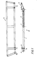
- Fig. 1 in schematischer, auseinandergezogener Darstellung in Seitenansicht, den Fahrwerkrahmen und den Geräterahmen, wobei der Geräterahmen vom Fahrwerksrahmen abgehoben dargestellt ist, und
- Fig. 2 in Draufsicht schematisch in einer Teildarstellung den Fahrwerksrahmen.
- Fig. 1 in a schematic, exploded view in side view, the chassis frame and the device frame, the device frame is shown lifted from the chassis frame, and
- Fig. 2 in plan view schematically in a partial representation of the chassis frame.
Der Fahrzeugrahmen 28 ist im dargestellten Ausführungsbeispiel, wie insbes. aus Fig. 2 ersichtlich, als Leiterrahmen ausgebildet, der aus zwei parallel zueinander angeordneten Holmen 1 besteht, zwischen welchen Sprossen angeordnet sind. Die Sprossen können dabei Wellen 5, 9 aufweisen, die in den Holmen 1 schwenkbar in Lagern 6, 10 aufgenommen und im Bereich zwischen den Holmen 1 von Rohren 2, 3 umschlossen sind. Die Welle 9 trägt eine Federschwinge 12, um ein Kettenrad 23 federnd zu lagern. Die Welle 5 trägt an ihren Enden Radwippen 7. Als dritte Sprosse 19 ist ein torsionweiches U-Profil vorgesehen, das an Laschen 18 angeschraubt ist, die an den Holmen 1 befestigt sind. Die Holme 1 können als Formrohre ausgebildet sein, so daß sie Einschubteile 24 aufnehmen können, an denen eine Spannachse 17 zum Spannen der Raupen befestigt werden kann.In the exemplary embodiment shown, as can be seen in particular from FIG. 2, the vehicle frame 28 is designed as a lead frame which consists of two
Damit sich die Holme 1 gegeneinander nich verschieben können, wodurch in den Lagern 6 und 10 Kantenpressungen entstehen würden, ist an dem Rohr 2 ein Dreieckslenker 13 angebracht, welcher über einen Gelenkbolzen 25 im Bereich seiner Spitze mit einer elastischen, insbes. aus Gummi bestehenden Lagerung 14 verbunden ist. Die Lagerung 14 kann dabei als das Rohr 3 umschließende, am Rohr fixierte Gummibuchse ausgebildet sein. Die Streben des Dreiecklenkers 13 werden ebenfalls von verwindungsweichen U-Profilen gebildet. Eine um die Längsachse des Fahrwerkrahmens 28 auftretende Torsionsbeanspruchung führt zu Drehbewegungen in den Gelenken der Sprossen, ohne daß die bei starren Verbindungen üblichen Spannungen auftreten. Der Zusammenbau des Rahmens 28 erfolgt bei dieser Ausgestaltung so, daß die Holme 1 auf die Sprossen, nämlich die mit den Rohren 2, 3 versehenen Wellen 5, 9 aufgesteckt werden, wobei die Schwinge 12 miteingefädelt wird. Nach Aufsetzen der Fahrwerkswippen 7 wird durch die Montage von Deckscheiben 8 und 11, welche über Schrauben mit den Wellen 5 und 9 fest verbunden sind, ein Auseinanderfallen der Elemente verhindert. Als letzte Montagearbeit wird noch der Träger 19 mit den Laschen 18 verbunden.So that the
Der Fahrwerksrahmen 28 besitzt symmetrisch zu seiner Längsmittenebene angeordnet, zwei Gummilager 16, die in Gummi eingebettete Lagerbüchsen zur Aufnahme von Bolzen aufweisen,die Laschen 21 des Geräterahmens 20 durchsetzen. In der Längsmittenebene des Fahrzeugrahmens 28 befindet sich ein drittes, elastisches Lager für den Geräterahmen 20, das auf einer drehelastisch an einer Sprosse des Leiterrahmens gelagerten Konsole 15 ausgebildet ist. Die Konsole 15 ist mit einer horizontal ausgerichteten Auflage 4 für einen Flansch 22 des Geräterahmens 20 versehen. Die Auflagefläche 4 und der Flansch 22 sind durch Schrauben verbindbar, wobei in Fig. 2 die Mitten der Bohrungen für die Aufnahme der Schrauben auf der Fläche 4 durch Kreuze angedeutet sind.The undercarriage frame 28 has two
Die Konsole 15 besitzt ein Lagersauge 27, das über die elastische, von einer Gummibüchse gebildete Lagerung 14 für den Spitzenbereich des Dreiecklenkers 13 geschoben ist.The
Zur Verbindung des Geräterahmens 20 mit dem Fahrwerksrahmen 28 werden die Laschen 21 des Geräterahmens 20 mit den Gummilagern 16 des Fahrwerksrahmens 28, welche an der Sprosse 19 befestigt sind, über Bolzen 26 verbunden. Der Flansch 22 wird mit der Konsole 15, die mit dem Gummielement 14 ein Lager bildet, verschraubt. Durch die Gummielemente 14 und 16 wird eine elastische Dreipunktlagerung gebildet, auf der der als Fachwerk ausgebildete und daher starre Geräterahmen 20 gelagert ist.To connect the
Claims (8)
Applications Claiming Priority (2)
| Application Number | Priority Date | Filing Date | Title |
|---|---|---|---|
| AT0277485A ATA277485A (en) | 1985-09-23 | 1985-09-23 | TRACKED VEHICLE |
| AT2774/85 | 1985-09-23 |
Publications (2)
| Publication Number | Publication Date |
|---|---|
| EP0216752A2 true EP0216752A2 (en) | 1987-04-01 |
| EP0216752A3 EP0216752A3 (en) | 1988-06-01 |
Family
ID=3540084
Family Applications (1)
| Application Number | Title | Priority Date | Filing Date |
|---|---|---|---|
| EP86890260A Withdrawn EP0216752A3 (en) | 1985-09-23 | 1986-09-19 | Endless-track vehicle |
Country Status (6)
| Country | Link |
|---|---|
| US (1) | US4739849A (en) |
| EP (1) | EP0216752A3 (en) |
| JP (1) | JPS6285772A (en) |
| AT (1) | ATA277485A (en) |
| FI (1) | FI863808A (en) |
| NO (1) | NO863784L (en) |
Families Citing this family (1)
| Publication number | Priority date | Publication date | Assignee | Title |
|---|---|---|---|---|
| FI121111B (en) * | 2007-09-25 | 2010-07-15 | Ponsse Oyj | Arrangements in a forest machine and a forest machine |
Citations (2)
| Publication number | Priority date | Publication date | Assignee | Title |
|---|---|---|---|---|
| DE1278848B (en) * | 1962-10-16 | 1968-09-26 | Soc D Forges Et Ateliers Du Cr | Land vehicle with support or drive caterpillars, at least partially carried by an air cushion |
| US3446303A (en) * | 1966-06-22 | 1969-05-27 | Outboard Marine Corp | Endless track vehicle |
Family Cites Families (5)
| Publication number | Priority date | Publication date | Assignee | Title |
|---|---|---|---|---|
| US2604176A (en) * | 1948-10-25 | 1952-07-22 | Deere & Co | Tractor frame structure |
| FR1169351A (en) * | 1959-02-18 | 1958-12-26 | Lorraine Anciens Ets Dietrich | Vehicle, in particular police or military vehicle |
| US4226293A (en) * | 1979-03-16 | 1980-10-07 | Miller W. Corporation | Track-laying vehicle with improved suspension |
| JPS5751171Y2 (en) * | 1979-09-05 | 1982-11-08 | ||
| SE425557B (en) * | 1981-02-17 | 1982-10-11 | Skega Ab | FOR BAND DRIVEN VEHICLES PROVIDED BANDAGGREGAT |
-
1985
- 1985-09-23 AT AT0277485A patent/ATA277485A/en unknown
-
1986
- 1986-09-18 JP JP61218285A patent/JPS6285772A/en active Pending
- 1986-09-19 EP EP86890260A patent/EP0216752A3/en not_active Withdrawn
- 1986-09-22 FI FI863808A patent/FI863808A/en not_active IP Right Cessation
- 1986-09-23 US US06/910,891 patent/US4739849A/en not_active Expired - Fee Related
- 1986-09-23 NO NO863784A patent/NO863784L/en unknown
Patent Citations (2)
| Publication number | Priority date | Publication date | Assignee | Title |
|---|---|---|---|---|
| DE1278848B (en) * | 1962-10-16 | 1968-09-26 | Soc D Forges Et Ateliers Du Cr | Land vehicle with support or drive caterpillars, at least partially carried by an air cushion |
| US3446303A (en) * | 1966-06-22 | 1969-05-27 | Outboard Marine Corp | Endless track vehicle |
Also Published As
| Publication number | Publication date |
|---|---|
| FI863808A0 (en) | 1986-09-22 |
| FI863808A (en) | 1987-03-24 |
| ATA277485A (en) | 1989-12-15 |
| US4739849A (en) | 1988-04-26 |
| NO863784D0 (en) | 1986-09-23 |
| JPS6285772A (en) | 1987-04-20 |
| EP0216752A3 (en) | 1988-06-01 |
| NO863784L (en) | 1987-03-24 |
Similar Documents
| Publication | Publication Date | Title |
|---|---|---|
| DE938892C (en) | Rear suspension for motor vehicles with a rigid rear axle bridge | |
| EP0680869A2 (en) | Tracklaying gear for a harvester | |
| DE1168775B (en) | Chassis for multi-axle, especially three-axle vehicles | |
| DE2716372C2 (en) | Hydraulic excavator or the like with a driver's cab | |
| EP1840018A2 (en) | Crawler carriage | |
| DE2349272A1 (en) | FRONT SUSPENSION FOR MOTOR VEHICLES | |
| EP3061640A1 (en) | Portal wheel drive unit for an agricultural vehicle with portal axle | |
| DE3725920C2 (en) | ||
| EP0216752A2 (en) | Endless-track vehicle | |
| EP3180202B1 (en) | Suspension device for a vehicle axle of a vehicle | |
| DD207068A3 (en) | CHASSIS FOR SELF-OPERATING WORK MACHINES | |
| DE2445629A1 (en) | DRIVER'S CAB ON A VEHICLE AROUND A HORIZONTAL AXIS OF A JOINT | |
| DE1455887B1 (en) | Wheel suspension for a vehicle | |
| DE102009016935A1 (en) | Crossbeam for vehicle, particularly construction site vehicle, comprises two guide stands for connecting crossbeam to corresponding longitudinal supports of vehicle | |
| DE2820476A1 (en) | AUTOMOTIVE CRANE, ROLLER CRANE AND METHOD FOR THE PRODUCTION THEREOF | |
| DE102005046553A1 (en) | Crawler device for self-propelled harvester, has two supporting roller arrangements that lie transverse to running direction ofbelt and are arranged at separate retainers, where retainers are pivotable independent of each other | |
| DE2518711A1 (en) | CATERED VEHICLE CHASSIS | |
| DE820696C (en) | Motor vehicle manufactured according to cell construction | |
| EP0864250B1 (en) | Drive axle | |
| DE3707155C2 (en) | ||
| DE102004011934B4 (en) | Front axle unit for a toy vehicle | |
| EP2060476A1 (en) | Drive modification for an armoured howitzer | |
| DE2216307A1 (en) | TRACK-WIDTH-CHANGEABLE TRACK-WIDTH VEHICLE | |
| CH340141A (en) | Motor vehicle with at least three wheels | |
| DE2549910A1 (en) | MEDIUM ENGINE MOTOR VEHICLE |
Legal Events
| Date | Code | Title | Description |
|---|---|---|---|
| PUAI | Public reference made under article 153(3) epc to a published international application that has entered the european phase |
Free format text: ORIGINAL CODE: 0009012 |
|
| AK | Designated contracting states |
Kind code of ref document: A2 Designated state(s): CH DE FR IT LI SE |
|
| PUAL | Search report despatched |
Free format text: ORIGINAL CODE: 0009013 |
|
| AK | Designated contracting states |
Kind code of ref document: A3 Designated state(s): CH DE FR IT LI SE |
|
| STAA | Information on the status of an ep patent application or granted ep patent |
Free format text: STATUS: THE APPLICATION IS DEEMED TO BE WITHDRAWN |
|
| 18D | Application deemed to be withdrawn |
Effective date: 19881003 |
|
| RIN1 | Information on inventor provided before grant (corrected) |
Inventor name: RANNER, DIETRICH, DIPL.-ING. |