EP0216675B1 - Gleichachsiges einsetzbares Patronenventil mit Mehrfachfunktion und Anwendung bei einem doppelwirkenden Stellantrieb - Google Patents
Gleichachsiges einsetzbares Patronenventil mit Mehrfachfunktion und Anwendung bei einem doppelwirkenden Stellantrieb Download PDFInfo
- Publication number
- EP0216675B1 EP0216675B1 EP86401869A EP86401869A EP0216675B1 EP 0216675 B1 EP0216675 B1 EP 0216675B1 EP 86401869 A EP86401869 A EP 86401869A EP 86401869 A EP86401869 A EP 86401869A EP 0216675 B1 EP0216675 B1 EP 0216675B1
- Authority
- EP
- European Patent Office
- Prior art keywords
- pressure
- port
- valve
- oil
- slide
- Prior art date
- Legal status (The legal status is an assumption and is not a legal conclusion. Google has not performed a legal analysis and makes no representation as to the accuracy of the status listed.)
- Expired
Links
- 230000000694 effects Effects 0.000 title description 2
- 230000009471 action Effects 0.000 claims description 4
- 230000001276 controlling effect Effects 0.000 claims 3
- 230000001105 regulatory effect Effects 0.000 claims 2
- 238000011144 upstream manufacturing Methods 0.000 claims 1
- 238000002955 isolation Methods 0.000 description 4
- 238000006073 displacement reaction Methods 0.000 description 3
- 230000036316 preload Effects 0.000 description 2
- 206010003497 Asphyxia Diseases 0.000 description 1
- 241000219422 Urtica Species 0.000 description 1
- 235000009108 Urtica dioica Nutrition 0.000 description 1
- 238000010276 construction Methods 0.000 description 1
- 230000001419 dependent effect Effects 0.000 description 1
- 239000012530 fluid Substances 0.000 description 1
- 230000007246 mechanism Effects 0.000 description 1
- 230000004048 modification Effects 0.000 description 1
- 238000012986 modification Methods 0.000 description 1
- 210000000056 organ Anatomy 0.000 description 1
- 230000000750 progressive effect Effects 0.000 description 1
- 230000000717 retained effect Effects 0.000 description 1
Images
Classifications
-
- F—MECHANICAL ENGINEERING; LIGHTING; HEATING; WEAPONS; BLASTING
- F15—FLUID-PRESSURE ACTUATORS; HYDRAULICS OR PNEUMATICS IN GENERAL
- F15B—SYSTEMS ACTING BY MEANS OF FLUIDS IN GENERAL; FLUID-PRESSURE ACTUATORS, e.g. SERVOMOTORS; DETAILS OF FLUID-PRESSURE SYSTEMS, NOT OTHERWISE PROVIDED FOR
- F15B13/00—Details of servomotor systems ; Valves for servomotor systems
- F15B13/02—Fluid distribution or supply devices characterised by their adaptation to the control of servomotors
- F15B13/04—Fluid distribution or supply devices characterised by their adaptation to the control of servomotors for use with a single servomotor
- F15B13/0401—Valve members; Fluid interconnections therefor
- F15B13/0405—Valve members; Fluid interconnections therefor for seat valves, i.e. poppet valves
-
- Y—GENERAL TAGGING OF NEW TECHNOLOGICAL DEVELOPMENTS; GENERAL TAGGING OF CROSS-SECTIONAL TECHNOLOGIES SPANNING OVER SEVERAL SECTIONS OF THE IPC; TECHNICAL SUBJECTS COVERED BY FORMER USPC CROSS-REFERENCE ART COLLECTIONS [XRACs] AND DIGESTS
- Y10—TECHNICAL SUBJECTS COVERED BY FORMER USPC
- Y10T—TECHNICAL SUBJECTS COVERED BY FORMER US CLASSIFICATION
- Y10T137/00—Fluid handling
- Y10T137/8593—Systems
- Y10T137/87169—Supply and exhaust
- Y10T137/87217—Motor
- Y10T137/87225—Fluid motor
-
- Y—GENERAL TAGGING OF NEW TECHNOLOGICAL DEVELOPMENTS; GENERAL TAGGING OF CROSS-SECTIONAL TECHNOLOGIES SPANNING OVER SEVERAL SECTIONS OF THE IPC; TECHNICAL SUBJECTS COVERED BY FORMER USPC CROSS-REFERENCE ART COLLECTIONS [XRACs] AND DIGESTS
- Y10—TECHNICAL SUBJECTS COVERED BY FORMER USPC
- Y10T—TECHNICAL SUBJECTS COVERED BY FORMER US CLASSIFICATION
- Y10T137/00—Fluid handling
- Y10T137/8593—Systems
- Y10T137/87169—Supply and exhaust
- Y10T137/87233—Biased exhaust valve
- Y10T137/87241—Biased closed
Definitions
- the present invention relates to multi-function insert cartridge valves and their applications to the control of a double-acting cylinder.
- a current distribution circuit on an excavator includes: manipulators for the remote control of distributors, distributors combining more and more functions (distribution, overpressure, recharge, throttling), large quantities of pipes that go to the receivers ( cylinders or motors), and finally increasingly complex safety and movement control valves incorporated into the cylinders without interposition of flexible.
- a first object of the invention is to provide a cartridge valve to be inserted into the distribution blocks to facilitate construction and after-sales interventions, these cartridge valves comprising overpressure and vacuum safety devices, so as to meet current requirements safety and precision of movements in all pressure and flow conditions.
- the cartridge valve to be inserted multifunctional coaxial hydraulic distribution is characterized in that it comprises an oil inlet orifice, an oil return orifice, an inlet orifice for the valve control pressure, an outlet orifice delivering the actuating pressure, an orifice for reading the actuating oil pressure, an orifice receiving this pressure information, a drainage orifice and a entry of the balancing pressure, a first compensating drawer biased towards a fully open position by a first spring, a second inner drawer concentric with the first giving the main adjustment of the oil inlet flow requested by a second spring at l against the control pressure delivered by the inlet port of this pressure towards the closed communication position between the oil pressure inlet port and the outlet orifice delivering the pres actuation sion, an isolation valve and a make-up valve urged by a third spring to bring these two valves back to the communication closed position towards the oil inlet and pressure reading port as regards the isolation valve and towards the oil return orifice to the reservoir with regard to
- the various drawers and valves have their axes of coaxial symmetry and are arranged in a cylindrical jacket in two parts comprising on its periphery and spaced longitudinally from each other, the various orifices.
- the cylindrical jacket is intended to be housed in a cavity having the respective bores corresponding to the dimensions of the jacket and the portion of the jacket located near the opening of the cavity has an external thread and an internal thread .
- a screw nut device for adjusting the force of the fourth spring is screwed into an internal thread.
- the third drawer has external bores and an internal bore placing the return orifice in communication with the actuating outlet orifice when the drawer is released from its seat under the action of the pressures present in the bores external.
- a final object of the invention was to apply these cartridge valves to the control of a double-acting cylinder in a distribution entirely incorporated in the cylinder to generate a simplification of the communications for the fluid between the different organs.
- valve housing cavities can be incorporated into the jacks and the connecting pipes are also incorporated into the jacks.
- valves can be connected to the jacks by flexible or rigid pipes.
- Each inlet or element designated by a letter will subscribe the number of the valve.
- the control port X1 belongs to the valve 1
- the control port X2 belongs to the valve 2.
- a pipe 5 formed in the body 3 of the control cylinder A connects an outlet port of the manipulator to the orifice X1 for arriving at the control pressure of the valve 1.
- the pipe 6 also formed in the body of the actuator A connects another outlet orifice of the manipulator to the orifice X2 arriving at the control pressure of the valve 2.
- the pipe 7 formed in the body of the jack A connects the outlet of the pump to the oil inlet orifices P1, P2 of each of the two valves 1 and 2.
- the pipe 8 also made in the body of the jack A connects the reservoir to the oil return orifices Ti, T2 of each of the two valves 1 and 2 on the one hand, and on the other hand to the drainage orifices Di, D2 by the pipes 80.
- the orifices S1, S2 of reading of the actuating oil pressure are each connected to the inputs of a selector 4 whose s Nettle is connected to line 9 connected to the pump flow control input.
- the opening S1 for actuating oil pressure is also connected by a pipe 90 to the opening B2 for balancing pressure inlet of the second valve 2, while the opening S2 for reading the actuating oil pressure of the second valve is connected by a pipe 91 to the inlet B1 of the balancing pressure inlet of the first valve.
- the pressure reading ports S1 and S2 are also respectively connected to s1 and s2 bringing the oil pressure information to the pressure compensator of each valve.
- An outlet orifice R1 of the first valve delivers the actuating pressure to the first chamber A1 actuating the rod A3 of the jack towards the outside, indicated by the direction of the arrow.
- an outlet orifice R2 of the second valve 2 also delivers the actuating pressure to a second chamber A2 of the jack actuating the rod A3 of the jack inward.
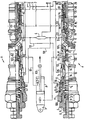
- Each of the valves 1, 2 is housed in the body 3 of the jack and more particularly in cavities formed by the succession of bores 29 to 36 co-axial and spaced longitudinally in the body of the jack.
- the bore 36 includes a thread in which is screwed an external thread F2 of the jacket 100 of the cartridge valve.
- This jacket 100 in two parts assembled between the levels of the bores 33 and 34 has the orifices indicated above with the exception of the orifice D1 which is placed at the bottom of the cavity intended to receive the valve.
- This jacket 100 includes the bores intended to receive the various drawers and valves constituting the valve and a channel H putting the orifice R1 in communication with the orifice S1 or the orifice P1 according to the position of the second drawer J1.
- the oil coming from the pressure inlet orifice P1 first crosses the flow control orifices of the first pressure compensating slide N1 which is biased towards a position of full opening of the passage by a first preload spring r1 , for example three or six bars.
- the pressure arrives in the groove of the drawer J1 and tends to compress the opening spring of the compensator in order to reduce the oil flow.
- the pressure reading made in S1 will be brought back to s1 to help the preload spring r1 of the pressure compensator to decrease strangulation.
- the second drawer J1 in the order of passage of the oil arriving through the pressure inlet orifice, is permanently biased by a second spring r2 towards a rest position in which the chamber formed by the diameter 10 of the back of drawer J1 and the internal bore of the compensating drawer is reduced to its minimum volume. In this position the drawer J1 prevents the communication of the orifice P1 with on the one hand the orifice S1 and on the other hand the orifice R1.
- This drawer J1 also has an internal bore 15 which makes it possible to put the orifice S1 in communication with the orifice D1.
- a valve C In the pipe H internal to the jacket of the valve, a valve C is urged permanently by a third spring r3 towards a closed or insulating position in which this valve C rests on the seat 101 belonging to the jacket of the valve .
- the liner 100 has in its internal bore Q an internal thread F1 on which a threaded screw L is mounted, itself supporting a screw system U and lock nut V, at the end of which are mounted a ball Y and a stop plate Z.
- the orifice T1 In this position of the balancing drawer E1, the orifice T1 is in communication with the internal bore 14 of the balancing drawer E1 but any communication of this bore with the orifice R1 is prevented.
- the orifice B1 is in communication with a chamber formed by the external bore 11 of the balancing slide E1 and the internal bore of the jacket 100, this chamber having in this position its minimum volume.
- the balancing slide E1 also has, near its end 16, a second external bore 12 of diameter smaller than the bore in which it is housed and making it possible to have an annular section, in general, of one third or one fifth of the section annular corresponding to bore 11.
- the pressure of the control circuit modulated by the manipulator arrives at the orifice X1 and ensures between these two pressure values a displacement of the first slide J1 between a zero stroke and a maximum stroke modulating the oil inlet flow rate between the zero and the maximum.
- the oil then moves from the inlet port P1 to the actuation outlet port R1, connected with the chamber A1 of the jack situated at the bottom of the latter to release the rod A3.
- the orifice S1 provides a pressure reading which will be used by the circuit selector 4, the pipe 9 and the inlet orifice of the oil flow control regulator of the self-regulating pump to adjust the assembly. pressure flow on demand.
- the flow will be adjusted according to the position of the manipulator, position chosen by the operator of the machine and the pressure will be adjusted according to the positive or negative charge.
- the balancing slide E2 of the second valve makes it possible to play the role of maximum pressure valve and of balancing valve.
- the balancing drawer E2 tends to move away from the seat 102 by fighting against its calibration spring r4 under the effect of two forces (a) and (b) which add up.
- the first force (a) is due to the pressure brought to the orifice R2 and applying to the annular section of the end opposite to the spring of the balancing drawer E2 of the valve 2, this pressure tending to spread the drawer balancing E2 of the support of its seat 102 and ensures the maximum pressure valve function.
- the second force (b) is constituted by the pressure which applies to the annular section corresponding to the bore 11 of the balancing slide E2 of the second valve.
- This section is normally three to five times greater than the annular section corresponding to the pressure relief valve located at the part opposite the calibration spring and helps to open the communication between the ports R2 and T2.
- This force (b) resulting from the pressure delivered to the orifice B2 from the pressure reading orifice S1 constitutes the balancing valve function.
- valve 2 becomes the control valve while the valve 1 becomes the balancing valve.
- the balancing slide E2 allows, in its pressure relief valve function, to evacuate the oil between the orifices R2 and T2 in the direction of movement, but this displacement causes a depression in the chamber A1 and, consequently, on the orifice R1.
- the make-up valve G1 is then unbalanced and causes its spring r2 to move back so as to allow passage between the orifices T1 and R1 of the valve 1 to fill the vacuum.
- the two input and output control elements constituted respectively by the first drawer J and the second balancing drawer E are nor improperly designed to work together in a single cartridge to be inserted, but they can be adapted to be dissociated and then constitute independent cartridges to be inserted ensuring, one the input control function, the other the output control function .
- the cartridge valve, as described can be used in the case where the regulation of the inlet flow is ensured by a potentiometric control transformed into a hydraulic control at modulated pressure by means of an electro-valve.
Landscapes
- Engineering & Computer Science (AREA)
- Physics & Mathematics (AREA)
- Fluid Mechanics (AREA)
- Mechanical Engineering (AREA)
- General Engineering & Computer Science (AREA)
- Fluid-Pressure Circuits (AREA)
- Safety Valves (AREA)
- Earth Drilling (AREA)
- Check Valves (AREA)
- Multiple-Way Valves (AREA)
Claims (12)
Priority Applications (1)
| Application Number | Priority Date | Filing Date | Title |
|---|---|---|---|
| AT86401869T ATE46941T1 (de) | 1985-08-26 | 1986-08-25 | Gleichachsiges einsetzbares patronenventil mit mehrfachfunktion und anwendung bei einem doppelwirkenden stellantrieb. |
Applications Claiming Priority (2)
| Application Number | Priority Date | Filing Date | Title |
|---|---|---|---|
| FR8512707A FR2586463B1 (fr) | 1985-08-26 | 1985-08-26 | Valves cartouches a inserer multi-fonctions coaxiales et application a la commande d'un verin a double effet |
| FR8512707 | 1985-08-26 |
Publications (2)
| Publication Number | Publication Date |
|---|---|
| EP0216675A1 EP0216675A1 (de) | 1987-04-01 |
| EP0216675B1 true EP0216675B1 (de) | 1989-10-04 |
Family
ID=9322376
Family Applications (1)
| Application Number | Title | Priority Date | Filing Date |
|---|---|---|---|
| EP86401869A Expired EP0216675B1 (de) | 1985-08-26 | 1986-08-25 | Gleichachsiges einsetzbares Patronenventil mit Mehrfachfunktion und Anwendung bei einem doppelwirkenden Stellantrieb |
Country Status (6)
| Country | Link |
|---|---|
| US (1) | US4706547A (de) |
| EP (1) | EP0216675B1 (de) |
| JP (1) | JPS6252205A (de) |
| AT (1) | ATE46941T1 (de) |
| DE (1) | DE3666075D1 (de) |
| FR (1) | FR2586463B1 (de) |
Families Citing this family (3)
| Publication number | Priority date | Publication date | Assignee | Title |
|---|---|---|---|---|
| ES2004356A6 (es) * | 1986-12-26 | 1989-01-01 | Hiac Valman S A | Distribuidor para cilindros hidraulicos |
| US5794651A (en) * | 1996-03-13 | 1998-08-18 | General Hydraulics Corporation | Valve adaptor cap |
| ITRE20020002A1 (it) * | 2002-01-11 | 2003-07-11 | Bucher Hydraulics S P A | Gruppo valvolare complesso per circuiti idraulici, in particolare perl'unita' di potenza |
Family Cites Families (9)
| Publication number | Priority date | Publication date | Assignee | Title |
|---|---|---|---|---|
| US3227179A (en) * | 1964-05-28 | 1966-01-04 | Nils O Rosaen | Cartridge valves |
| US3283779A (en) * | 1964-08-19 | 1966-11-08 | Nils O Rosaen | Cartridge valves |
| FR2485104B1 (fr) * | 1980-03-31 | 1986-05-23 | Meca Ind Ind Agricoles Atel | Perfectionnements apportes aux dispositifs hydrauliques de securite pour moteurs hydrauliques |
| US4353289A (en) * | 1980-05-29 | 1982-10-12 | Sperry Corporation | Power transmission |
| DE3048746A1 (de) * | 1980-12-23 | 1982-07-22 | Robert Bosch Gmbh, 7000 Stuttgart | Hydraulikanlage |
| FI72579C (fi) * | 1981-11-12 | 1987-06-08 | Vickers Inc | Transmission. |
| US4475442A (en) * | 1982-02-08 | 1984-10-09 | Vickers, Incorporated | Power transmission |
| US4569272A (en) * | 1982-03-22 | 1986-02-11 | Vickers, Incorporated | Power transmission |
| CA1202228A (en) * | 1982-03-22 | 1986-03-25 | Henry D. Taylor | Power transmission |
-
1985
- 1985-08-26 FR FR8512707A patent/FR2586463B1/fr not_active Expired
-
1986
- 1986-08-21 US US06/898,524 patent/US4706547A/en not_active Expired - Fee Related
- 1986-08-25 AT AT86401869T patent/ATE46941T1/de not_active IP Right Cessation
- 1986-08-25 EP EP86401869A patent/EP0216675B1/de not_active Expired
- 1986-08-25 DE DE8686401869T patent/DE3666075D1/de not_active Expired
- 1986-08-26 JP JP61198279A patent/JPS6252205A/ja active Pending
Also Published As
| Publication number | Publication date |
|---|---|
| DE3666075D1 (en) | 1989-11-09 |
| FR2586463B1 (fr) | 1987-12-24 |
| FR2586463A1 (fr) | 1987-02-27 |
| JPS6252205A (ja) | 1987-03-06 |
| US4706547A (en) | 1987-11-17 |
| EP0216675A1 (de) | 1987-04-01 |
| ATE46941T1 (de) | 1989-10-15 |
Similar Documents
| Publication | Publication Date | Title |
|---|---|---|
| JP4160530B2 (ja) | 制御弁装置及び圧力回路 | |
| EP0330575B1 (de) | Hydraulischer Kreislauf mit zugehörigem Sicherheitsventil für hydraulische Verbraucher | |
| BE1006612A3 (fr) | Commande reversible de coupure de la haute pression pour une pompe hydraulique a debit variable. | |
| EP0709577B1 (de) | Ventil mit vier Verbindungsöffnungen und zwei Stellungen | |
| FR3035925A1 (fr) | Dispositif pour la commande hydraulique optimisee en energie d'un verin a double effet | |
| WO2012093240A1 (fr) | Dispositif de régulation de pression avec détection de la position neutre | |
| EP0216675B1 (de) | Gleichachsiges einsetzbares Patronenventil mit Mehrfachfunktion und Anwendung bei einem doppelwirkenden Stellantrieb | |
| FR2509830A1 (fr) | Regulateur de debit pour des circuits hydrauliques | |
| CA3062434C (fr) | Circuit hydraulique de manoeuvre de train d'atterissage d'aeronef | |
| FR2796106A1 (fr) | Dispositif de distribution hydraulique a fonction de verrouillage | |
| EP0459840B1 (de) | Steuereinrichtung für einen doppelt wirkenden Arbeitszylinder | |
| FR2672944A1 (fr) | Distributeur proportionnel et ensemble de commande d'une pluralite de recepteurs hydrauliques comportant pour chaque recepteur un tel distributeur. | |
| EP1342645A1 (de) | Hydraulische Lenkvorrichtung | |
| FR2570521A1 (fr) | Dispositif de regulation a deux domaines de pression | |
| FR2499642A1 (fr) | Soupape de surete pour presse actionnable hydrauliquement | |
| FR2509829A1 (fr) | Regulateur de pression a commande par solenoide | |
| EP1137888B1 (de) | Hydraulisches wegeventil | |
| FR2621354A1 (fr) | Dispositif de commande independant de la charge pour appareils utilisateurs hydrauliques | |
| FR2701531A1 (fr) | Electrovalve pneumatique proportionnelle. | |
| FR2695861A1 (fr) | Dispositif hydraulique sensible de sélection de vitesse et de puissance adapté sur un système de commande synchrone de vérins multiples de presse. | |
| EP0176381B1 (de) | Hydraulisches Hochdruckwegeventil mit Vorsteuerdruckerzeuger | |
| FR2715484A1 (fr) | Servovalve de régulation de pression. | |
| FR2711433A1 (fr) | Régulateur coaxial de débit. | |
| FR2662226A1 (fr) | Vanne de commande directionnelle. | |
| FR2732438A1 (fr) | Soupape a deux voies du type a detection de pression a double sens |
Legal Events
| Date | Code | Title | Description |
|---|---|---|---|
| PUAI | Public reference made under article 153(3) epc to a published international application that has entered the european phase |
Free format text: ORIGINAL CODE: 0009012 |
|
| AK | Designated contracting states |
Kind code of ref document: A1 Designated state(s): AT BE CH DE FR GB IT LI LU NL SE |
|
| 17P | Request for examination filed |
Effective date: 19870908 |
|
| 17Q | First examination report despatched |
Effective date: 19881110 |
|
| GRAA | (expected) grant |
Free format text: ORIGINAL CODE: 0009210 |
|
| AK | Designated contracting states |
Kind code of ref document: B1 Designated state(s): AT BE CH DE FR GB IT LI LU NL SE |
|
| REF | Corresponds to: |
Ref document number: 46941 Country of ref document: AT Date of ref document: 19891015 Kind code of ref document: T |
|
| REF | Corresponds to: |
Ref document number: 3666075 Country of ref document: DE Date of ref document: 19891109 |
|
| GBT | Gb: translation of ep patent filed (gb section 77(6)(a)/1977) | ||
| ITF | It: translation for a ep patent filed | ||
| PLBE | No opposition filed within time limit |
Free format text: ORIGINAL CODE: 0009261 |
|
| STAA | Information on the status of an ep patent application or granted ep patent |
Free format text: STATUS: NO OPPOSITION FILED WITHIN TIME LIMIT |
|
| PGFP | Annual fee paid to national office [announced via postgrant information from national office to epo] |
Ref country code: GB Payment date: 19900813 Year of fee payment: 5 |
|
| PG25 | Lapsed in a contracting state [announced via postgrant information from national office to epo] |
Ref country code: AT Effective date: 19900825 |
|
| PG25 | Lapsed in a contracting state [announced via postgrant information from national office to epo] |
Ref country code: SE Effective date: 19900826 |
|
| ITTA | It: last paid annual fee | ||
| PG25 | Lapsed in a contracting state [announced via postgrant information from national office to epo] |
Ref country code: LU Free format text: LAPSE BECAUSE OF NON-PAYMENT OF DUE FEES Effective date: 19900831 Ref country code: LI Effective date: 19900831 Ref country code: CH Effective date: 19900831 Ref country code: BE Effective date: 19900831 |
|
| 26N | No opposition filed | ||
| BERE | Be: lapsed |
Owner name: LE BLON HUBERT Effective date: 19900831 |
|
| PG25 | Lapsed in a contracting state [announced via postgrant information from national office to epo] |
Ref country code: NL Effective date: 19910301 |
|
| NLV4 | Nl: lapsed or anulled due to non-payment of the annual fee | ||
| REG | Reference to a national code |
Ref country code: CH Ref legal event code: PL |
|
| PGFP | Annual fee paid to national office [announced via postgrant information from national office to epo] |
Ref country code: FR Payment date: 19910729 Year of fee payment: 6 |
|
| PG25 | Lapsed in a contracting state [announced via postgrant information from national office to epo] |
Ref country code: GB Effective date: 19910825 |
|
| PGFP | Annual fee paid to national office [announced via postgrant information from national office to epo] |
Ref country code: DE Payment date: 19910903 Year of fee payment: 6 |
|
| GBPC | Gb: european patent ceased through non-payment of renewal fee | ||
| PG25 | Lapsed in a contracting state [announced via postgrant information from national office to epo] |
Ref country code: FR Effective date: 19930430 |
|
| PG25 | Lapsed in a contracting state [announced via postgrant information from national office to epo] |
Ref country code: DE Effective date: 19930501 |
|
| REG | Reference to a national code |
Ref country code: FR Ref legal event code: ST |
|
| EUG | Se: european patent has lapsed |
Ref document number: 86401869.2 Effective date: 19910410 |
|
| PG25 | Lapsed in a contracting state [announced via postgrant information from national office to epo] |
Ref country code: IT Free format text: LAPSE BECAUSE OF NON-PAYMENT OF DUE FEES;WARNING: LAPSES OF ITALIAN PATENTS WITH EFFECTIVE DATE BEFORE 2007 MAY HAVE OCCURRED AT ANY TIME BEFORE 2007. THE CORRECT EFFECTIVE DATE MAY BE DIFFERENT FROM THE ONE RECORDED. Effective date: 20050825 |