EP0216124B1 - Apparatus and method for retaining an insert in an electrical connector - Google Patents
Apparatus and method for retaining an insert in an electrical connector Download PDFInfo
- Publication number
- EP0216124B1 EP0216124B1 EP86111360A EP86111360A EP0216124B1 EP 0216124 B1 EP0216124 B1 EP 0216124B1 EP 86111360 A EP86111360 A EP 86111360A EP 86111360 A EP86111360 A EP 86111360A EP 0216124 B1 EP0216124 B1 EP 0216124B1
- Authority
- EP
- European Patent Office
- Prior art keywords
- insert
- shell
- wall
- end portion
- passageway
- Prior art date
- Legal status (The legal status is an assumption and is not a legal conclusion. Google has not performed a legal analysis and makes no representation as to the accuracy of the status listed.)
- Expired - Lifetime
Links
- 238000000034 method Methods 0.000 title claims description 10
- 230000014759 maintenance of location Effects 0.000 claims description 37
- 238000003780 insertion Methods 0.000 claims description 7
- 230000037431 insertion Effects 0.000 claims description 7
- 239000000463 material Substances 0.000 claims description 5
- 239000012811 non-conductive material Substances 0.000 claims 2
- 239000004593 Epoxy Substances 0.000 description 6
- 239000012815 thermoplastic material Substances 0.000 description 4
- 238000013459 approach Methods 0.000 description 3
- 230000013011 mating Effects 0.000 description 3
- 238000002955 isolation Methods 0.000 description 2
- 238000004519 manufacturing process Methods 0.000 description 2
- 230000007246 mechanism Effects 0.000 description 2
- 239000002184 metal Substances 0.000 description 2
- 229910052751 metal Inorganic materials 0.000 description 2
- RYGMFSIKBFXOCR-UHFFFAOYSA-N Copper Chemical compound [Cu] RYGMFSIKBFXOCR-UHFFFAOYSA-N 0.000 description 1
- 239000004695 Polyether sulfone Substances 0.000 description 1
- 239000004697 Polyetherimide Substances 0.000 description 1
- 239000004963 Torlon Substances 0.000 description 1
- 229920003997 Torlon® Polymers 0.000 description 1
- 230000001154 acute effect Effects 0.000 description 1
- 230000000295 complement effect Effects 0.000 description 1
- 229910052802 copper Inorganic materials 0.000 description 1
- 239000010949 copper Substances 0.000 description 1
- 229920006393 polyether sulfone Polymers 0.000 description 1
- 229920001601 polyetherimide Polymers 0.000 description 1
- 230000002787 reinforcement Effects 0.000 description 1
- 230000000717 retained effect Effects 0.000 description 1
- 229920001169 thermoplastic Polymers 0.000 description 1
- 229920001187 thermosetting polymer Polymers 0.000 description 1
- 239000004416 thermosoftening plastic Substances 0.000 description 1
Images

Classifications
-
- H—ELECTRICITY
- H01—ELECTRIC ELEMENTS
- H01R—ELECTRICALLY-CONDUCTIVE CONNECTIONS; STRUCTURAL ASSOCIATIONS OF A PLURALITY OF MUTUALLY-INSULATED ELECTRICAL CONNECTING ELEMENTS; COUPLING DEVICES; CURRENT COLLECTORS
- H01R13/00—Details of coupling devices of the kinds covered by groups H01R12/70 or H01R24/00 - H01R33/00
- H01R13/40—Securing contact members in or to a base or case; Insulating of contact members
- H01R13/42—Securing in a demountable manner
- H01R13/424—Securing in base or case composed of a plurality of insulating parts having at least one resilient insulating part
-
- H—ELECTRICITY
- H01—ELECTRIC ELEMENTS
- H01R—ELECTRICALLY-CONDUCTIVE CONNECTIONS; STRUCTURAL ASSOCIATIONS OF A PLURALITY OF MUTUALLY-INSULATED ELECTRICAL CONNECTING ELEMENTS; COUPLING DEVICES; CURRENT COLLECTORS
- H01R13/00—Details of coupling devices of the kinds covered by groups H01R12/70 or H01R24/00 - H01R33/00
- H01R13/46—Bases; Cases
- H01R13/516—Means for holding or embracing insulating body, e.g. casing, hoods
-
- Y—GENERAL TAGGING OF NEW TECHNOLOGICAL DEVELOPMENTS; GENERAL TAGGING OF CROSS-SECTIONAL TECHNOLOGIES SPANNING OVER SEVERAL SECTIONS OF THE IPC; TECHNICAL SUBJECTS COVERED BY FORMER USPC CROSS-REFERENCE ART COLLECTIONS [XRACs] AND DIGESTS
- Y10—TECHNICAL SUBJECTS COVERED BY FORMER USPC
- Y10T—TECHNICAL SUBJECTS COVERED BY FORMER US CLASSIFICATION
- Y10T29/00—Metal working
- Y10T29/49—Method of mechanical manufacture
- Y10T29/49002—Electrical device making
- Y10T29/49117—Conductor or circuit manufacturing
- Y10T29/49204—Contact or terminal manufacturing
- Y10T29/49208—Contact or terminal manufacturing by assembling plural parts
- Y10T29/49218—Contact or terminal manufacturing by assembling plural parts with deforming
Definitions
- This invention relates to a separable electrical connector having an improved arrangement an for retaining an insert within a shell.
- An electrical connector of the type herein includes a dielectric insert which is retained in a metallic shell and carries a plurality of conductive terminals in electrical isolation from the shell for mating with a respective plurality of terminals in a second connector.
- the dielectric insert typically is hard and can either be comprised of a thermoset or a thermoplastic material with good dielectric properties for circuit isolation.
- Patent 4,099,233 issuing to Bouvier, respectively, April 26, 1977 and July 11, 1978 and each incorporated herein by reference it has been found that deforming the conductive mesh laminate by a crushing action caused the mesh to invade into the bond interface between a hard wafer and a resilient grommet whereupon a conductive path could be established between the outer row of terminals and the shell thereby causing a ground short to exist.
- Another approach has utilized a non-metallic laminate mesh. This offers good retention and assures a non-conductive path between the insert and shell but is hard to handle and process.
- non-conductive insert retention system that would be inexpensive, adaptable to a wide range of connector shells having different diameters and internal cross-sections, easy to manufacture, easy to assemble, and assure the user of insert retention integrity would be desirable.
- This invention contemplates an electrical connector comprising a metal shell that includes an annular groove on its inner wall, a dielectric insert having an outer periphery disposed in the shell so that an annular passageway is provided between the shell and the insert, and a retention arrangement for retaining the insert in the shell.
- a retention member comprised of an elongated strip of a deformable thermoplastic material is scalloped along its front face by longitudinal slots to provide a plurality of axially weakened columns which will collapsingly fold onto one another and stack together in accordion-like fashion and radially interferencingly wedge themselves in the annular passageway when the strip front face engages an axial wall at the end of the passageway formed between the insert and the shell.
- the inner wall includes an annular groove which encircles the outer periphery and cooperation between axial faces of the groove and radial folds requires shear forces to shear the accordion-like folds for the insert to be removed.
- the electrical connector comprises a shell having a cylindrical inner wall, an insert (24) having a cylindrical outer periphery, disposed within the shell so as to form an annular passageway defined by and located between the inner wall and the outer periphery of the insert, and retention means for retaining the insert within said shell, said retention means being characterized by an annular retention member of deformable material being foldingly wedged radially between the shell and the insert, said retention member including a forward portion and a rearward portion with said forward end portion being longitudinally slotted and collapsingly folded axially and radially whereby to be wedged interferencingly in the passageway, said retention member having the forward end portion substantially thinner than the rearward end portion and the rearward end portion defining a forwardly facing endwall, and said insert defining a shoulder leading to the passageway between the inner wall and the outer periphery whereby when the forwardly facing endwall abuts said shoulder during assembly, the assembler knows that assembly operation is
- Figure 1 a juxtaposl cross-sectional exploded view of a connector assembly including an insert adapted to be inserted into a shell and a tool positioned to force a tubular sleeve between the assembled shell and insert.
- Figure 2 is an enlarged section view of an insert retention member.
- Figure 3 is a plan view of an elongated strip and an insert retention member of Figure 2 formed therefrom.
- Figure 4 is a partial cross-section of the insert disposed within the shell and the retention member being inserted between an axial annular passageway therebetween.
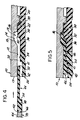
- Figure 5 shows an assembled relationship
- Figure 1 illustrates a metallic connector shell 10, a dielectric insert 24, an insert retention member 44, and an insert tool 70 each coaxially aligned for assembly along a central axis.
- the insert and shell have complementary cross-sections such that when the insert is fitted into the shell, an axially extending annular passageway 72 is formed for receiving the insert member (See FIGURE 4).
- the shell and insert are generally cylindrical and of one piece but are shown in section for clarity of description of the insert retention.
- the shell 10 is open at each of its opposite axial ends and includes a forward mating end 11, a rearward entry end 13, an inner wall 12, an annular groove 19 disposed within the inner wall, and a radial flange 20 extending radially inward from the inner wall.
- the annular groove comprises a first axial face 16 disposed in a plane generally perpendicular to the central axis and facing rearwardly, a flared frusto-conical axial face 18 facing forwardly, and an annular wall 14 extending between the faces and generally coaxially extending relative to the inner wall.
- the flange 20 includes an endwall 22 that faces rearwardly and provides a stop which limits inward axial insertion of the insert into the shell.
- the insert 24 is typically comprised of Torlon and includes a front face 28, a rear face 26, and a plurality of passages 30 extending between the faces for receiving an electrical contact (not shown) therein for mating.
- the cross-section of the insert is stepped and includes a first surface 34 defining an outer periphery, a second surface 40 extending radially outward from the outer periphery to define a collar 32, and a third surface 42 extending radially inward from the outer periphery to define a shoulder 41 leading to an inward recess, each of the surfaces being generally coaxially defined relative to the central axis of the insert.
- the collar 32 includes a rear face 36 facing rearwardly, and a front face 38 facing forwardly and adapted to abut endwall 22 of the radial flange.
- the second surface 40 of the insert which defines the outer periphery of the collar is adapted to clearance fit against the inner wall 12 of the shell 10 so as to position the rearwardly facing end wall 36 of the collar medially of the annular groove 19 which will encircle it when the insert is within the shell.
- a pair of cylindrical inserts are bonded together into a single member with the bond interface indicated at 31.
- the retention member 44 is formed into a tubular sleeve from a flat sheet of a thermoplastic material, the sleeve having a forward portion 46 substantially thinner than a rearward portion 48 with a front face 50 being scalloped by slots 60 extending therefrom towards its to a rear face 52.
- Retention member 44 is comprised of a material that would be resiliently deformable and not be crackable, have good properties of elongation, shear strength and high temperature capability.
- a material is a thermoplastic such as would include a polyether sulfone and a polyetherimide.
- the insertion tool 70 includes a body 68 and a cylindrical mandrel 64 extending to a front action surface 66 adapted to engage the rear face 52 of the retention member 44 whereby to drive the retention member into the annular passageway 72 formed between the inner wall of shell and the outer periphery of the insert when the insert is inserted within the shell.
- FIGURE 2 shows a cross-section of the retention member 44 such as would be seen looking along lines II-II of FIGURE 3.
- the retention member has generally parallel top and bottom faces for each of its forward and rearward portions 46, 48, the rearward portion being the thicker of the two and defining a forwardly facing endwall 54 which is adapted to engage the shoulder 41 on the insert whereby to trap the rearward portion of the two piece insert.
- FIGURE 3 shows the retention member 44 as being formed from an elongated-continuous strip 44' of non-conductive thermoplastic material.
- a plurality of slots 60 which extend peripendicularly from its front face 50 inwardly towards its rear face 52 are formed to define a plurality of laterally separated weakened axial columns 62 which are adapted to collapse upon a sufficient external force being placed on them.
- the strip is first slotted and then severed into strip portions each which define the retention member 44.
- the severing could be perpendicular to the front and rear faces of the strip 44 whereby form a rectangular shape having lateral endfaces 56, 58, as shown, or at an acute angle to the front and the rear endfaces whereby to form a parallelogram shape (not shown).
- the respective lateral endfaces are wrapped around and brought into abutment with one another to form a tubular sleeve having a cross-section sized for insertion into the annular passageway.
- the shape of the slots 60 while being shown as having a U-shaped root, could be otherwise.
- FIGURE 4 shows the insert 24 clearance fit within the shell 10 with the front face 38 of its collar 32 abutting against the endwall 22 of the radial flange 20 whereby to position the insert therewithin so that the annular groove encircles the collar.
- the axially extending annular passageway 72 is formed between the outer periphery of the insert and the inner wall 12 of the shell.
- the retention member 44 is inserted inwardly into the passageway 72 from the rearward entry end 13 of the shell.
- rear face 36 is shown as being substantially at a right angle, a chamfer (i.e., tapered) surface would also work).
- FIGURE 5 shows the result of continued insertion of the retention member into the passageway.
- the front face 50 is driven into engagement with the rearwardly facing axial face 16 of the annular groove 19.
- Further external force causes the columns 62 to collapse in an accordion-like fashion whereby to fold over themselves and have portions thereof driven radially upward as the column folds stack. Portions of the folded accordion are interferencingly wedged within the annular groove and around the insert whereby to engage the insert and shell.
- the endwall 54 abuts the shoulder 41 of the, the assembler knows that the insert staking operation is complete.
Landscapes
- Connector Housings Or Holding Contact Members (AREA)
Description
- This invention relates to a separable electrical connector having an improved arrangement an for retaining an insert within a shell.
- An electrical connector of the type herein includes a dielectric insert which is retained in a metallic shell and carries a plurality of conductive terminals in electrical isolation from the shell for mating with a respective plurality of terminals in a second connector. The dielectric insert typically is hard and can either be comprised of a thermoset or a thermoplastic material with good dielectric properties for circuit isolation.
- Previous approaches for retaining an insert assembly within the shell have included upset staking of the shell, metal ring staking, and copper mesh/epoxy laminate staking. Each of these offer excellent retention but may introduce a conductive path between the insert assembly and shell. In "Electrical Connector" U.S. Patent 4,019,799 and "Method of Making Electrical Connector" U.S. Patent 4,099,233 issuing to Bouvier, respectively, April 26, 1977 and July 11, 1978 and each incorporated herein by reference it has been found that deforming the conductive mesh laminate by a crushing action caused the mesh to invade into the bond interface between a hard wafer and a resilient grommet whereupon a conductive path could be established between the outer row of terminals and the shell thereby causing a ground short to exist.
- Other approaches have included epoxy staking, interference fits with epoxy, and self-snapping mechanisms, all of which protect against a conductive path to the shell but do not offer a good insert retention system. Epoxy does not have an internal reinforcement to prevent break up under extreme conditions of temperature and pressure. Further, the interference fits with epoxy rely on the epoxy to take up sloppy fits due to tolerancing. Slippage and loose friction fits could lead to insert pull-out. Self snapping mechanisms introduce loose inserts due to tolerancing difficulties.
- Another approach has utilized a non-metallic laminate mesh. This offers good retention and assures a non-conductive path between the insert and shell but is hard to handle and process.
- Provision of a non-conductive insert retention system that would be inexpensive, adaptable to a wide range of connector shells having different diameters and internal cross-sections, easy to manufacture, easy to assemble, and assure the user of insert retention integrity would be desirable.
- This invention contemplates an electrical connector comprising a metal shell that includes an annular groove on its inner wall, a dielectric insert having an outer periphery disposed in the shell so that an annular passageway is provided between the shell and the insert, and a retention arrangement for retaining the insert in the shell.
- In accordance with this invention, as defined in claim 1, a retention member comprised of an elongated strip of a deformable thermoplastic material is scalloped along its front face by longitudinal slots to provide a plurality of axially weakened columns which will collapsingly fold onto one another and stack together in accordion-like fashion and radially interferencingly wedge themselves in the annular passageway when the strip front face engages an axial wall at the end of the passageway formed between the insert and the shell. The inner wall includes an annular groove which encircles the outer periphery and cooperation between axial faces of the groove and radial folds requires shear forces to shear the accordion-like folds for the insert to be removed.
- More precisely, according to the present invention, as defined in claim 1, the electrical connector comprises a shell having a cylindrical inner wall, an insert (24) having a cylindrical outer periphery, disposed within the shell so as to form an annular passageway defined by and located between the inner wall and the outer periphery of the insert, and retention means for retaining the insert within said shell, said retention means being characterized by an annular retention member of deformable material being foldingly wedged radially between the shell and the insert, said retention member including a forward portion and a rearward portion with said forward end portion being longitudinally slotted and collapsingly folded axially and radially whereby to be wedged interferencingly in the passageway, said retention member having the forward end portion substantially thinner than the rearward end portion and the rearward end portion defining a forwardly facing endwall, and said insert defining a shoulder leading to the passageway between the inner wall and the outer periphery whereby when the forwardly facing endwall abuts said shoulder during assembly, the assembler knows that assembly operation is complete.
- Figure 1 a partiel cross-sectional exploded view of a connector assembly including an insert adapted to be inserted into a shell and a tool positioned to force a tubular sleeve between the assembled shell and insert.
- Figure 2 is an enlarged section view of an insert retention member.
- Figure 3 is a plan view of an elongated strip and an insert retention member of Figure 2 formed therefrom.
- Figure 4 is a partial cross-section of the insert disposed within the shell and the retention member being inserted between an axial annular passageway therebetween.
- Figure 5 shows an assembled relationship.
- Referring now to the drawings, Figure 1 illustrates a metallic connector shell 10, a
dielectric insert 24, aninsert retention member 44, and aninsert tool 70 each coaxially aligned for assembly along a central axis. The insert and shell have complementary cross-sections such that when the insert is fitted into the shell, an axially extendingannular passageway 72 is formed for receiving the insert member (See FIGURE 4). The shell and insert are generally cylindrical and of one piece but are shown in section for clarity of description of the insert retention. - The shell 10 is open at each of its opposite axial ends and includes a forward mating end 11, a rearward entry end 13, an
inner wall 12, an annular groove 19 disposed within the inner wall, and aradial flange 20 extending radially inward from the inner wall. The annular groove comprises a firstaxial face 16 disposed in a plane generally perpendicular to the central axis and facing rearwardly, a flared frusto-conicalaxial face 18 facing forwardly, and anannular wall 14 extending between the faces and generally coaxially extending relative to the inner wall. Theflange 20 includes anendwall 22 that faces rearwardly and provides a stop which limits inward axial insertion of the insert into the shell. - The
insert 24 is typically comprised of Torlon and includes afront face 28, arear face 26, and a plurality ofpassages 30 extending between the faces for receiving an electrical contact (not shown) therein for mating. The cross-section of the insert is stepped and includes afirst surface 34 defining an outer periphery, asecond surface 40 extending radially outward from the outer periphery to define acollar 32, and athird surface 42 extending radially inward from the outer periphery to define ashoulder 41 leading to an inward recess, each of the surfaces being generally coaxially defined relative to the central axis of the insert. Thecollar 32 includes arear face 36 facing rearwardly, and afront face 38 facing forwardly and adapted toabut endwall 22 of the radial flange. Thesecond surface 40 of the insert which defines the outer periphery of the collar is adapted to clearance fit against theinner wall 12 of the shell 10 so as to position the rearwardly facingend wall 36 of the collar medially of the annular groove 19 which will encircle it when the insert is within the shell. As shown, a pair of cylindrical inserts are bonded together into a single member with the bond interface indicated at 31. - The
retention member 44 is formed into a tubular sleeve from a flat sheet of a thermoplastic material, the sleeve having aforward portion 46 substantially thinner than arearward portion 48 with afront face 50 being scalloped byslots 60 extending therefrom towards its to arear face 52. -
Retention member 44 is comprised of a material that would be resiliently deformable and not be crackable, have good properties of elongation, shear strength and high temperature capability. Such a material is a thermoplastic such as would include a polyether sulfone and a polyetherimide. - The
insertion tool 70 includes abody 68 and acylindrical mandrel 64 extending to afront action surface 66 adapted to engage therear face 52 of theretention member 44 whereby to drive the retention member into theannular passageway 72 formed between the inner wall of shell and the outer periphery of the insert when the insert is inserted within the shell. - FIGURE 2 shows a cross-section of the
retention member 44 such as would be seen looking along lines II-II of FIGURE 3. The retention member has generally parallel top and bottom faces for each of its forward andrearward portions endwall 54 which is adapted to engage theshoulder 41 on the insert whereby to trap the rearward portion of the two piece insert. - FIGURE 3 shows the
retention member 44 as being formed from an elongated-continuous strip 44' of non-conductive thermoplastic material. As the strip is advanced in the direction "A" a plurality ofslots 60 which extend peripendicularly from itsfront face 50 inwardly towards itsrear face 52 are formed to define a plurality of laterally separated weakenedaxial columns 62 which are adapted to collapse upon a sufficient external force being placed on them. The strip is first slotted and then severed into strip portions each which define theretention member 44. The severing could be perpendicular to the front and rear faces of thestrip 44 whereby form a rectangular shape havinglateral endfaces 56, 58, as shown, or at an acute angle to the front and the rear endfaces whereby to form a parallelogram shape (not shown). Following each severing, depending on the shape or configuration desired, the respective lateral endfaces are wrapped around and brought into abutment with one another to form a tubular sleeve having a cross-section sized for insertion into the annular passageway. The shape of theslots 60, while being shown as having a U-shaped root, could be otherwise. - FIGURE 4 shows the
insert 24 clearance fit within the shell 10 with thefront face 38 of itscollar 32 abutting against theendwall 22 of theradial flange 20 whereby to position the insert therewithin so that the annular groove encircles the collar. The axially extendingannular passageway 72 is formed between the outer periphery of the insert and theinner wall 12 of the shell. Theretention member 44 is inserted inwardly into thepassageway 72 from the rearward entry end 13 of the shell. The difference between the distance betweenendwall 54 of therearward portion 48 and thefront face 50 of theforward portion 46 and the distance between theshoulder 41 of the insert and theaxial face 16 of the shell defines a collapsible volume which is adapted to collapse in accordion like fashion whereby to radially wedge itself within the annular groove 19. - While
rear face 36 is shown as being substantially at a right angle, a chamfer (i.e., tapered) surface would also work). - FIGURE 5 shows the result of continued insertion of the retention member into the passageway. The
front face 50 is driven into engagement with the rearwardly facingaxial face 16 of the annular groove 19. Further external force causes thecolumns 62 to collapse in an accordion-like fashion whereby to fold over themselves and have portions thereof driven radially upward as the column folds stack. Portions of the folded accordion are interferencingly wedged within the annular groove and around the insert whereby to engage the insert and shell. When theendwall 54 abuts theshoulder 41 of the, the assembler knows that the insert staking operation is complete. - Because of the accordion-like being formed by a plurality of radial column folds and disposed between axial faces and in the annular groove, insert withdrawal can only come about as a result of shear forces sufficient to shear the folds.
Claims (10)
- Electrical connector assembly including a shell (10) having a cylindrical inner wall (12), an insert (24) having a cylindrical outer periphery, disposed within the shell so as to form an annular passageway defined by and located between the inner wall and the outer periphery of the insert, and retention means for retaining the insert within said shell, said retention means comprising an annular retention member (44) of deformable material foldingly wedged radially between the shell and the insert, said retention member including a forward portion (46) and a rearward portion (48) with said forward end portion being longitudinally slotted (60) and collapsingly folded axially and radially whereby to be wedged interferencingly in the passageway, said connector assembly being further characterized by said retention member having the forward end portion substantially thinner than the rearward end portion and the rearward end portion defining a forwardly facing endwall (54), and said insert defining a shoulder (41) leading to the passageway between the inner wall and the outer periphery whereby when the forwardly facing endwall abuts said shoulder during assembly, the assembler knows that assembly operation is complete.
- The electrical connector assembly as recited in claim 1, wherein said retention member comprises an axially elongated strip (44') of material being formed into a cylinder, said strip having a front and a rear face (50, 52) and a plurality of longitudinal slots (60) extending rearwardly from the front face to define a plurality of laterally separated weakened longitudinal columns (62) which foldingly collapse in the passageway.
- The connector assembly as recited in claim 2, wherein the inner wall of said shell includes a flange (20) and an annular groove (19) each encircling said outer periphery, and said insert has a front face (38) abutting said flange, said annular groove including said axial face (16) and receiving some of the forward end portion of said collapsing columns with said axial face defining a stop for collapsingly folding the slotted front face of said retention member.
- The connector assembly as recited in claim 2, wherein the inner wall, the outer periphery and the annular passageway are coaxially extending, and the annular groove (19) includes said axial face (16), a frusto-conical forwardly facing second axial face (18), and a second inner wall (14) extending between the axial faces.
- A method of retaining a generally cylindrical insert (24) within a shell (10) having a generally cylindrical inner wall (12), the steps of the method comprising :
forming an annular groove (19) on the inner wall to provide a rearwardly facing axial face (16) ;
reducing the cross-section of the insert to reduce the outer periphery and provde a collar (32) that extends radially outward therefrom, the inner wall having a diameter dimensioned so as to clearance fit about the collar and define an annular passageway (72) about the outer periphery and the insert being formed such that it defines a shoulder (41) leading to the annular passageway defined by the insert ;
removing a plurality of strip portions from an elongated strip (44') of plastically deformable non-conductive material whereby to define a plurality of laterally separated longitudinally weakened columns (62) ;
inserting the insert into the shell so that the collar is adajcent to the axial face ;
forming the strip into a retention member (44) having a cross-section corresponding to that of the annular passageway, and the forming operation being such that the forward end portion is substantially thinner than the rearward end portion thereof, the rearward end portion defining a forwardly facing endwall (54) ; and
axially inserting the retention member into the passageway a distance sufficient to have its front face (50) engage the axial face with continued insertion being with an external force sufficient to cause the columns to axially and radially collapse within the passageway and fold together in accordion-like fashion to interferencingly wedge between the insert and the shell with the forwardly facing endwall abutting the shoulder of the inset. - The method as recited in claim 5, wherein the removing step includes longitudinally slotting the strip (44') from the front face rearwardly to provide a plurality of laterally spaced longitudinal slots (60) and columns (62).
- The method as recited in claim 5, wherein said elongated strip (44') is continuous and of generally uniform cross-section and includes a rear face (52) generally parallel to its front face, and the forming step further comprises cutting the elongated strip into a strip portion having lateral ends (56, 58) which are abutted to form the retention member (44).
- The method as recited in claim 7, wherein the cutting is in a direction generally perpendicular to the front and rear faces (50, 52) whereby to form a generally rectangular shaped strip portion, and the forming step includes abutting the lateral ends to provide a closed sleeve.
- The method as recited in claim 7, wherein the cutting is in a direction generally angled to the front and rear faces (50, 52) whereby to form a generally parallelogram shaped strip portion, and the forming step includes abutting the lateral ends to provide a closed sleeve.
- A method of retaining a generally cylindrical insert (24) within a generally cylindrical shell (10), an outer diameter of the insert being slightly less than an inner diameter of the shell, the method comprising the steps of
removing a cylindrical portion of one of said shell and insert to provide an axial face (16) facing rearwardly, said removed cylindrical portion leaving an axially extending annular passageway (72) between the shell and the insert, and further, said insert formed such that it defines a shoulder (41) spaced from the inner wall of the shell leading to the annular passageway ;
forming a tubular sleeve (44) from a piece of deformable non-conductive material, said sleeve having a front and rear face (50, 52) and forward end portion including a plurality of generally equi-angularly spaced, axially weakened, longitudinal columns (62), and the sleeve being formed such that the forward end is substantially thinner than the rearward end, the rearward end defining a forwardly facing endwall (54) ; and
inserting the forward end portion of the deformable sleeve into the annular passageway until its front face engages the axial face, the insertion force than being increased by an amount sufficient to cause the forward end portion of the columns to foldingly collapse therewithin in accordion-like fashion to form a radially folded wedged accordion portion therebetween, and the insertion being conducted until the forwardly facing endwall abuts the shoulder of the insert.
Applications Claiming Priority (2)
| Application Number | Priority Date | Filing Date | Title |
|---|---|---|---|
| US06/781,294 US4703987A (en) | 1985-09-27 | 1985-09-27 | Apparatus and method for retaining an insert in an electrical connector |
| US781294 | 1985-09-27 |
Publications (3)
| Publication Number | Publication Date |
|---|---|
| EP0216124A2 EP0216124A2 (en) | 1987-04-01 |
| EP0216124A3 EP0216124A3 (en) | 1988-10-05 |
| EP0216124B1 true EP0216124B1 (en) | 1993-03-24 |
Family
ID=25122283
Family Applications (1)
| Application Number | Title | Priority Date | Filing Date |
|---|---|---|---|
| EP86111360A Expired - Lifetime EP0216124B1 (en) | 1985-09-27 | 1986-08-16 | Apparatus and method for retaining an insert in an electrical connector |
Country Status (4)
| Country | Link |
|---|---|
| US (1) | US4703987A (en) |
| EP (1) | EP0216124B1 (en) |
| JP (1) | JPH07111889B2 (en) |
| DE (1) | DE3688116T2 (en) |
Families Citing this family (74)
| Publication number | Priority date | Publication date | Assignee | Title |
|---|---|---|---|---|
| EP0480337B1 (en) * | 1990-10-09 | 1995-08-09 | Matrix Science Corporation | Insert retention gas tight seal for an electrical connector and method of making same |
| US5470257A (en) * | 1994-09-12 | 1995-11-28 | John Mezzalingua Assoc. Inc. | Radial compression type coaxial cable end connector |
| MXPA02000336A (en) | 2000-05-10 | 2002-06-21 | Thomas & Betts Int | Coaxial connector having detachable locking sleeve. |
| USD535259S1 (en) | 2001-05-09 | 2007-01-16 | Thomas & Betts International, Inc. | Coaxial cable connector |
| US7241172B2 (en) | 2004-04-16 | 2007-07-10 | Thomas & Betts International Inc. | Coaxial cable connector |
| US7063565B2 (en) | 2004-05-14 | 2006-06-20 | Thomas & Betts International, Inc. | Coaxial cable connector |
| US20060110977A1 (en) | 2004-11-24 | 2006-05-25 | Roger Matthews | Connector having conductive member and method of use thereof |
| US8157589B2 (en) | 2004-11-24 | 2012-04-17 | John Mezzalingua Associates, Inc. | Connector having a conductively coated member and method of use thereof |
| US7114990B2 (en) | 2005-01-25 | 2006-10-03 | Corning Gilbert Incorporated | Coaxial cable connector with grounding member |
| IL174146A0 (en) | 2005-03-11 | 2006-08-01 | Thomas & Betts Int | Coaxial connector with a cable gripping feature |
| CN101253656B (en) | 2005-06-27 | 2012-01-11 | 普罗布兰德国际有限公司 | End connectors for coaxial cables |
| US7455549B2 (en) | 2005-08-23 | 2008-11-25 | Thomas & Betts International, Inc. | Coaxial cable connector with friction-fit sleeve |
| US7288002B2 (en) | 2005-10-19 | 2007-10-30 | Thomas & Betts International, Inc. | Coaxial cable connector with self-gripping and self-sealing features |
| CA2563865C (en) | 2005-10-20 | 2010-04-27 | Thomas & Betts International, Inc. | Prepless coaxial cable connector |
| JP4856940B2 (en) * | 2005-12-09 | 2012-01-18 | 日立オートモティブシステムズ株式会社 | Rotating electric machine and manufacturing method thereof |
| US7588460B2 (en) | 2007-04-17 | 2009-09-15 | Thomas & Betts International, Inc. | Coaxial cable connector with gripping ferrule |
| US7794275B2 (en) | 2007-05-01 | 2010-09-14 | Thomas & Betts International, Inc. | Coaxial cable connector with inner sleeve ring |
| US7566236B2 (en) | 2007-06-14 | 2009-07-28 | Thomas & Betts International, Inc. | Constant force coaxial cable connector |
| US8113875B2 (en) | 2008-09-30 | 2012-02-14 | Belden Inc. | Cable connector |
| US8025518B2 (en) | 2009-02-24 | 2011-09-27 | Corning Gilbert Inc. | Coaxial connector with dual-grip nut |
| US8029315B2 (en) | 2009-04-01 | 2011-10-04 | John Mezzalingua Associates, Inc. | Coaxial cable connector with improved physical and RF sealing |
| US7824216B2 (en) | 2009-04-02 | 2010-11-02 | John Mezzalingua Associates, Inc. | Coaxial cable continuity connector |
| US7892005B2 (en) | 2009-05-19 | 2011-02-22 | John Mezzalingua Associates, Inc. | Click-tight coaxial cable continuity connector |
| US8573996B2 (en) | 2009-05-22 | 2013-11-05 | Ppc Broadband, Inc. | Coaxial cable connector having electrical continuity member |
| US9570845B2 (en) | 2009-05-22 | 2017-02-14 | Ppc Broadband, Inc. | Connector having a continuity member operable in a radial direction |
| US9017101B2 (en) | 2011-03-30 | 2015-04-28 | Ppc Broadband, Inc. | Continuity maintaining biasing member |
| US8287320B2 (en) | 2009-05-22 | 2012-10-16 | John Mezzalingua Associates, Inc. | Coaxial cable connector having electrical continuity member |
| US8444445B2 (en) | 2009-05-22 | 2013-05-21 | Ppc Broadband, Inc. | Coaxial cable connector having electrical continuity member |
| US8272893B2 (en) | 2009-11-16 | 2012-09-25 | Corning Gilbert Inc. | Integrally conductive and shielded coaxial cable connector |
| TWI549386B (en) | 2010-04-13 | 2016-09-11 | 康寧吉伯特公司 | Coaxial connector with inhibited ingress and improved grounding |
| US8079860B1 (en) | 2010-07-22 | 2011-12-20 | John Mezzalingua Associates, Inc. | Cable connector having threaded locking collet and nut |
| US8152551B2 (en) | 2010-07-22 | 2012-04-10 | John Mezzalingua Associates, Inc. | Port seizing cable connector nut and assembly |
| US8113879B1 (en) | 2010-07-27 | 2012-02-14 | John Mezzalingua Associates, Inc. | One-piece compression connector body for coaxial cable connector |
| US8888526B2 (en) | 2010-08-10 | 2014-11-18 | Corning Gilbert, Inc. | Coaxial cable connector with radio frequency interference and grounding shield |
| US8556656B2 (en) | 2010-10-01 | 2013-10-15 | Belden, Inc. | Cable connector with sliding ring compression |
| US8167636B1 (en) | 2010-10-15 | 2012-05-01 | John Mezzalingua Associates, Inc. | Connector having a continuity member |
| US8323053B2 (en) | 2010-10-18 | 2012-12-04 | John Mezzalingua Associates, Inc. | Connector having a constant contact nut |
| US8167646B1 (en) | 2010-10-18 | 2012-05-01 | John Mezzalingua Associates, Inc. | Connector having electrical continuity about an inner dielectric and method of use thereof |
| US8167635B1 (en) | 2010-10-18 | 2012-05-01 | John Mezzalingua Associates, Inc. | Dielectric sealing member and method of use thereof |
| US8075338B1 (en) | 2010-10-18 | 2011-12-13 | John Mezzalingua Associates, Inc. | Connector having a constant contact post |
| TWI558022B (en) | 2010-10-27 | 2016-11-11 | 康寧吉伯特公司 | Push-on cable connector with a coupler and retention and release mechanism |
| US8337229B2 (en) | 2010-11-11 | 2012-12-25 | John Mezzalingua Associates, Inc. | Connector having a nut-body continuity element and method of use thereof |
| US8414322B2 (en) | 2010-12-14 | 2013-04-09 | Ppc Broadband, Inc. | Push-on CATV port terminator |
| US8398421B2 (en) | 2011-02-01 | 2013-03-19 | John Mezzalingua Associates, Inc. | Connector having a dielectric seal and method of use thereof |
| US8157588B1 (en) | 2011-02-08 | 2012-04-17 | Belden Inc. | Cable connector with biasing element |
| US8342879B2 (en) | 2011-03-25 | 2013-01-01 | John Mezzalingua Associates, Inc. | Coaxial cable connector |
| US8465322B2 (en) | 2011-03-25 | 2013-06-18 | Ppc Broadband, Inc. | Coaxial cable connector |
| US8366481B2 (en) | 2011-03-30 | 2013-02-05 | John Mezzalingua Associates, Inc. | Continuity maintaining biasing member |
| US8388377B2 (en) | 2011-04-01 | 2013-03-05 | John Mezzalingua Associates, Inc. | Slide actuated coaxial cable connector |
| US8348697B2 (en) | 2011-04-22 | 2013-01-08 | John Mezzalingua Associates, Inc. | Coaxial cable connector having slotted post member |
| US9203167B2 (en) | 2011-05-26 | 2015-12-01 | Ppc Broadband, Inc. | Coaxial cable connector with conductive seal |
| US9711917B2 (en) | 2011-05-26 | 2017-07-18 | Ppc Broadband, Inc. | Band spring continuity member for coaxial cable connector |
| US8758050B2 (en) | 2011-06-10 | 2014-06-24 | Hiscock & Barclay LLP | Connector having a coupling member for locking onto a port and maintaining electrical continuity |
| US8591244B2 (en) | 2011-07-08 | 2013-11-26 | Ppc Broadband, Inc. | Cable connector |
| US9190744B2 (en) | 2011-09-14 | 2015-11-17 | Corning Optical Communications Rf Llc | Coaxial cable connector with radio frequency interference and grounding shield |
| US20130072057A1 (en) | 2011-09-15 | 2013-03-21 | Donald Andrew Burris | Coaxial cable connector with integral radio frequency interference and grounding shield |
| US9147955B2 (en) | 2011-11-02 | 2015-09-29 | Ppc Broadband, Inc. | Continuity providing port |
| US9136654B2 (en) | 2012-01-05 | 2015-09-15 | Corning Gilbert, Inc. | Quick mount connector for a coaxial cable |
| US9407016B2 (en) | 2012-02-22 | 2016-08-02 | Corning Optical Communications Rf Llc | Coaxial cable connector with integral continuity contacting portion |
| US9287659B2 (en) | 2012-10-16 | 2016-03-15 | Corning Optical Communications Rf Llc | Coaxial cable connector with integral RFI protection |
| US9147963B2 (en) | 2012-11-29 | 2015-09-29 | Corning Gilbert Inc. | Hardline coaxial connector with a locking ferrule |
| US9153911B2 (en) | 2013-02-19 | 2015-10-06 | Corning Gilbert Inc. | Coaxial cable continuity connector |
| US9172154B2 (en) | 2013-03-15 | 2015-10-27 | Corning Gilbert Inc. | Coaxial cable connector with integral RFI protection |
| WO2014172554A1 (en) | 2013-04-17 | 2014-10-23 | Ppc Broadband, Inc. | Post assembly for coaxial cable connectors |
| US10290958B2 (en) | 2013-04-29 | 2019-05-14 | Corning Optical Communications Rf Llc | Coaxial cable connector with integral RFI protection and biasing ring |
| EP3000154B1 (en) | 2013-05-20 | 2019-05-01 | Corning Optical Communications RF LLC | Coaxial cable connector with integral rfi protection |
| US9548557B2 (en) | 2013-06-26 | 2017-01-17 | Corning Optical Communications LLC | Connector assemblies and methods of manufacture |
| US9048599B2 (en) | 2013-10-28 | 2015-06-02 | Corning Gilbert Inc. | Coaxial cable connector having a gripping member with a notch and disposed inside a shell |
| WO2016073309A1 (en) | 2014-11-03 | 2016-05-12 | Corning Optical Communications Rf Llc | Coaxial cable connector with integral rfi protection |
| US10033122B2 (en) | 2015-02-20 | 2018-07-24 | Corning Optical Communications Rf Llc | Cable or conduit connector with jacket retention feature |
| US9590287B2 (en) | 2015-02-20 | 2017-03-07 | Corning Optical Communications Rf Llc | Surge protected coaxial termination |
| US10211547B2 (en) | 2015-09-03 | 2019-02-19 | Corning Optical Communications Rf Llc | Coaxial cable connector |
| US9525220B1 (en) | 2015-11-25 | 2016-12-20 | Corning Optical Communications LLC | Coaxial cable connector |
| US12034264B2 (en) | 2021-03-31 | 2024-07-09 | Corning Optical Communications Rf Llc | Coaxial cable connector assemblies with outer conductor engagement features and methods for using the same |
Family Cites Families (11)
| Publication number | Priority date | Publication date | Assignee | Title |
|---|---|---|---|---|
| US1914109A (en) * | 1931-04-22 | 1933-06-13 | Connecticut Telephone & Elec | Electric terminal connecter |
| US2974400A (en) * | 1952-03-11 | 1961-03-14 | Frank J Sowa | Method of making an insulated electrical connector |
| US2865011A (en) * | 1954-06-24 | 1958-12-16 | Herman H Dejadon | Heavy duty terminal connector |
| US3909936A (en) * | 1974-09-30 | 1975-10-07 | Jimmy C Ray | Plastic film insert |
| US4053200A (en) * | 1975-11-13 | 1977-10-11 | Bunker Ramo Corporation | Cable connector |
| GB1537475A (en) * | 1975-11-14 | 1978-12-29 | Sealectro Corp | Electrical feedthrough devices |
| US4019799A (en) * | 1976-02-11 | 1977-04-26 | The Bendix Corporation | Electrical connector |
| US4059330A (en) * | 1976-08-09 | 1977-11-22 | John Schroeder | Solderless prong connector for coaxial cable |
| US4063351A (en) * | 1976-12-20 | 1977-12-20 | International Telephone And Telegraph Corporation | Electrical connector assembly apparatus and method of connector fabrication |
| AT366514B (en) * | 1980-03-19 | 1982-04-26 | Neutrik Ag | ELECTRICAL CONNECTOR |
| US4389081A (en) * | 1980-11-14 | 1983-06-21 | The Bendix Corporation | Electrical connector coupling ring |
-
1985
- 1985-09-27 US US06/781,294 patent/US4703987A/en not_active Expired - Lifetime
-
1986
- 1986-08-16 DE DE86111360T patent/DE3688116T2/en not_active Expired - Fee Related
- 1986-08-16 EP EP86111360A patent/EP0216124B1/en not_active Expired - Lifetime
- 1986-09-25 JP JP61225036A patent/JPH07111889B2/en not_active Expired - Lifetime
Also Published As
| Publication number | Publication date |
|---|---|
| US4703987A (en) | 1987-11-03 |
| EP0216124A3 (en) | 1988-10-05 |
| JPS6276269A (en) | 1987-04-08 |
| JPH07111889B2 (en) | 1995-11-29 |
| DE3688116T2 (en) | 1993-10-21 |
| DE3688116D1 (en) | 1993-04-29 |
| EP0216124A2 (en) | 1987-04-01 |
Similar Documents
| Publication | Publication Date | Title |
|---|---|---|
| EP0216124B1 (en) | Apparatus and method for retaining an insert in an electrical connector | |
| EP0220402B1 (en) | Retaining an insert in an electrical connector | |
| US4362350A (en) | Contact retention assembly | |
| US4688876A (en) | Connector for coaxial cable | |
| EP0326447B1 (en) | Socket contact for an electrical connector | |
| EP0105766B1 (en) | Socket contact for electrical connector and method of manufacture | |
| EP0480337B1 (en) | Insert retention gas tight seal for an electrical connector and method of making same | |
| US5482480A (en) | Connector terminal | |
| EP0152748B1 (en) | Electrical connector assembly having means for shielding electromagnetic interference | |
| EP0053050A1 (en) | Electrical connector coupling pin | |
| JP3386156B2 (en) | Coaxial connector | |
| US4648681A (en) | Filtered electrical plug | |
| US4262987A (en) | Electrical connector | |
| US4272149A (en) | One piece socket type electrical contacts | |
| US4589721A (en) | Electrical connector having pin contact receptacle with releasable retaining means | |
| EP0026117B1 (en) | Electrical contact for an electrical connector and method of making same | |
| US8272901B2 (en) | Crimp contacts and electrical connector assemblies including the same | |
| US4333703A (en) | Contact retention assembly | |
| US4373262A (en) | Electrical contact with locking device | |
| US4566752A (en) | Contact assembly for an electrical connector | |
| US4270825A (en) | Electrical connector assembly | |
| US4184245A (en) | Removal tool and method of using | |
| US4493527A (en) | Socket contact for electrical connectors | |
| US4365412A (en) | Method of making an electrical connector assembly | |
| US4381135A (en) | Socket type contact assembly |
Legal Events
| Date | Code | Title | Description |
|---|---|---|---|
| PUAI | Public reference made under article 153(3) epc to a published international application that has entered the european phase |
Free format text: ORIGINAL CODE: 0009012 |
|
| AK | Designated contracting states |
Kind code of ref document: A2 Designated state(s): DE FR GB IT |
|
| PUAL | Search report despatched |
Free format text: ORIGINAL CODE: 0009013 |
|
| AK | Designated contracting states |
Kind code of ref document: A3 Designated state(s): DE FR GB IT |
|
| 17P | Request for examination filed |
Effective date: 19890325 |
|
| RAP1 | Party data changed (applicant data changed or rights of an application transferred) |
Owner name: AMPHENOL CORPORATION |
|
| 17Q | First examination report despatched |
Effective date: 19910624 |
|
| GRAA | (expected) grant |
Free format text: ORIGINAL CODE: 0009210 |
|
| AK | Designated contracting states |
Kind code of ref document: B1 Designated state(s): DE FR GB IT |
|
| ITF | It: translation for a ep patent filed | ||
| REF | Corresponds to: |
Ref document number: 3688116 Country of ref document: DE Date of ref document: 19930429 |
|
| ET | Fr: translation filed | ||
| ITTA | It: last paid annual fee | ||
| PLBE | No opposition filed within time limit |
Free format text: ORIGINAL CODE: 0009261 |
|
| STAA | Information on the status of an ep patent application or granted ep patent |
Free format text: STATUS: NO OPPOSITION FILED WITHIN TIME LIMIT |
|
| 26N | No opposition filed | ||
| REG | Reference to a national code |
Ref country code: GB Ref legal event code: IF02 |
|
| PGFP | Annual fee paid to national office [announced via postgrant information from national office to epo] |
Ref country code: GB Payment date: 20030915 Year of fee payment: 18 |
|
| PGFP | Annual fee paid to national office [announced via postgrant information from national office to epo] |
Ref country code: FR Payment date: 20030923 Year of fee payment: 18 |
|
| PGFP | Annual fee paid to national office [announced via postgrant information from national office to epo] |
Ref country code: DE Payment date: 20031031 Year of fee payment: 18 |
|
| PG25 | Lapsed in a contracting state [announced via postgrant information from national office to epo] |
Ref country code: GB Free format text: LAPSE BECAUSE OF NON-PAYMENT OF DUE FEES Effective date: 20040816 |
|
| PG25 | Lapsed in a contracting state [announced via postgrant information from national office to epo] |
Ref country code: DE Free format text: LAPSE BECAUSE OF NON-PAYMENT OF DUE FEES Effective date: 20050301 |
|
| GBPC | Gb: european patent ceased through non-payment of renewal fee |
Effective date: 20040816 |
|
| PG25 | Lapsed in a contracting state [announced via postgrant information from national office to epo] |
Ref country code: FR Free format text: LAPSE BECAUSE OF NON-PAYMENT OF DUE FEES Effective date: 20050429 |
|
| REG | Reference to a national code |
Ref country code: FR Ref legal event code: ST |
|
| PG25 | Lapsed in a contracting state [announced via postgrant information from national office to epo] |
Ref country code: IT Free format text: LAPSE BECAUSE OF NON-PAYMENT OF DUE FEES;WARNING: LAPSES OF ITALIAN PATENTS WITH EFFECTIVE DATE BEFORE 2007 MAY HAVE OCCURRED AT ANY TIME BEFORE 2007. THE CORRECT EFFECTIVE DATE MAY BE DIFFERENT FROM THE ONE RECORDED. Effective date: 20050816 |