EP0480337B1 - Insert retention gas tight seal for an electrical connector and method of making same - Google Patents
Insert retention gas tight seal for an electrical connector and method of making same Download PDFInfo
- Publication number
- EP0480337B1 EP0480337B1 EP91116977A EP91116977A EP0480337B1 EP 0480337 B1 EP0480337 B1 EP 0480337B1 EP 91116977 A EP91116977 A EP 91116977A EP 91116977 A EP91116977 A EP 91116977A EP 0480337 B1 EP0480337 B1 EP 0480337B1
- Authority
- EP
- European Patent Office
- Prior art keywords
- insert
- shell
- ring
- annular
- receptacle
- Prior art date
- Legal status (The legal status is an assumption and is not a legal conclusion. Google has not performed a legal analysis and makes no representation as to the accuracy of the status listed.)
- Expired - Lifetime
Links
Images


Classifications
-
- H—ELECTRICITY
- H01—ELECTRIC ELEMENTS
- H01R—ELECTRICALLY-CONDUCTIVE CONNECTIONS; STRUCTURAL ASSOCIATIONS OF A PLURALITY OF MUTUALLY-INSULATED ELECTRICAL CONNECTING ELEMENTS; COUPLING DEVICES; CURRENT COLLECTORS
- H01R13/00—Details of coupling devices of the kinds covered by groups H01R12/70 or H01R24/00 - H01R33/00
- H01R13/40—Securing contact members in or to a base or case; Insulating of contact members
- H01R13/42—Securing in a demountable manner
- H01R13/424—Securing in base or case composed of a plurality of insulating parts having at least one resilient insulating part
-
- Y—GENERAL TAGGING OF NEW TECHNOLOGICAL DEVELOPMENTS; GENERAL TAGGING OF CROSS-SECTIONAL TECHNOLOGIES SPANNING OVER SEVERAL SECTIONS OF THE IPC; TECHNICAL SUBJECTS COVERED BY FORMER USPC CROSS-REFERENCE ART COLLECTIONS [XRACs] AND DIGESTS
- Y10—TECHNICAL SUBJECTS COVERED BY FORMER USPC
- Y10S—TECHNICAL SUBJECTS COVERED BY FORMER USPC CROSS-REFERENCE ART COLLECTIONS [XRACs] AND DIGESTS
- Y10S439/00—Electrical connectors
- Y10S439/901—Connector hood or shell
- Y10S439/903—Special latch for insert
-
- Y—GENERAL TAGGING OF NEW TECHNOLOGICAL DEVELOPMENTS; GENERAL TAGGING OF CROSS-SECTIONAL TECHNOLOGIES SPANNING OVER SEVERAL SECTIONS OF THE IPC; TECHNICAL SUBJECTS COVERED BY FORMER USPC CROSS-REFERENCE ART COLLECTIONS [XRACs] AND DIGESTS
- Y10—TECHNICAL SUBJECTS COVERED BY FORMER USPC
- Y10T—TECHNICAL SUBJECTS COVERED BY FORMER US CLASSIFICATION
- Y10T29/00—Metal working
- Y10T29/49—Method of mechanical manufacture
- Y10T29/49002—Electrical device making
- Y10T29/49117—Conductor or circuit manufacturing
- Y10T29/49204—Contact or terminal manufacturing
- Y10T29/49208—Contact or terminal manufacturing by assembling plural parts
Definitions
- the present invention relates to an insert retention, gas tight seal for an electrical connector and more particularly to a solid metal annular ring gas tight seal which becomes an integral part of the connector housing for both the receptacle and the plug.
- Expanding ring retainers for use in electrical connectors which provide limited movement and limited vibration deterioration of the connector insert are known.
- this insert member is a thin laminate which can be mechanically deformed until it substantially fills the space between the shell and the insert.
- the laminate member is made of a matrix of screen-like material, for example a wire screen, impregnated with an epoxy or other thermal setting material.
- Specific embodiments of the Bouvier device comprise a matrix material having a bronze screen.
- U.S. Patent No. 4,019,799, issued April 26, 1977 also to A.J. Bouvier, entitled “Electrical Connector”, discloses wrapping a deformable laminate around the members within an electrical connector housing and inserting the assembled members with the laminate into a shell thereby affixing the connector inserts immovable in this application.
- the laminate is a screen-like material impregnated with an epoxy.
- the Bouvier device describes a laminate deformed wherein it substantially fills the space including an annular groove within the insert of the housing. The laminate is deformed prior to the insertion of terminals using a pressure tool.
- the Gallusser, et al. patent discloses an annular groove on the inner wall and the dielectric insert having an outer periphery disposed within the connector shell so that an annular passageway is provided between the shell and the insert thereby providing a retention arrangement for retaining the insert in the shell.
- this insert retention member in the Gallusser, et al. patent incorporates an insert tool to insert and maintain the insert between the connector shell and the dielectric insert.
- the Gallusser, et al. device incorporates the use of a dielectric material such as a plastic because of the conductive path which occurs between the insert assembly and the shell when a copper mesh epoxy laminate or metal ring staking is used.
- the annular passageway formed between the connector insert and shell allows the longitudinal columns to collapse accordion style thereby radially wedging and locking in the columns in the passage and retaining the insert within the shell.
- an electrical connector having a metal shell includes an annular groove within the interior wall of the shell, wherein the dielectric insert has an outer periphery disposed within the shell so that there is an annular passageway between the shell and the insert.
- the Punako, et al. retention arrangement includes a thermoplastic material retention member longitudinally slotted along its front face providing a plurality of axially weakened columns that terminate in a leading edge such that each column can curl back 180° upon themselves to lock the forward end portion of each respective column.
- Each axially weakened column is forward of the respective column medium portion such that each column is weakened to collapsibly fold and stack in accordion-like fashion forming radial folds.
- These columns are then curled and folded after the leading edges have engaged in an axial wall of the annular groove at the end of the passageway, and the curled folded column portions interface and wedge in the passageway around the annular passageway thereby retaining the insert within the shell.
- the electrical connector has a housing including: a receptacle, a plug and a coupling nut, wherein the receptacle and plug each have an insulating insert which resides within the electrical connector housing or shell.
- Annular grooves are inscribed upon the interior surface of the electrical connector housing.
- Soft annealed metal cylindrical rings are inserted within the electrical connector housing for the receptacle and plug around the inserts, specifically within the annular grooves.
- a cylindrical tool operable to, under high pressure, collapse and expand the soft annular metal cylindrical rings within the annular groove thereby providing a gas tight seal.
- the present invention solves the problem of the vibrational deterioration of the insulating insert within an electrical connector as used in the construction industry for connectors subjected to high vibration.
- the invention provides an electrical connector insert retention system that can be provided in a high vibrational environmentally destructive arena guaranteeing the continued mating of the receptacle and plug without receptacle and plug insert degradation.
- a method of providing an insert retention gas tight seal in an electrical connector is defined in claim 3.
- an insert retention gas tight seal for an electrical connector comprises a standard electrical connector having a receptacle, plug and coupling nut which has annular grooves inscribed within the interior walls of the receptacle and plug shells.
- the inserts for the receptacle and plug are inserted by hand into the respective shells, and an annular aluminum or other soft metal annular ring is inserted surrounding the inserts between the interior surfaces of the receptacle shell and plug shell and the exterior surfaces of the inserts.
- a beveled cylindrical tool is pressed against the soft metal annular rings under high pressure collapsing and expanding the soft metal into the inscribed grooves of the receptacle and plug shell interior surfaces.
- the combination of the inscribed grooves, the soft metal impressed within the grooves, and the receptacle and plug shell interior surfaces create a gas tight seal surrounding the inserts and a stable support for the inserts when they are subjected to high vibration.
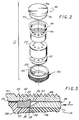
- Figure 1 is a schematic representation exploded cross sectional view of a connector 5 having a receptacle and a plug, each incorporating an insert retention, gas tight seal with the receptacle and plug connectors to be secured together with a coupling nut 14.
- the shell 10 of the receptacle has a top 16 and bottom 18 as viewed in Figure 1. Protruding from the top 16 of the receptacle shell 10 is the first receptacle insert 26.
- This insert 26 has a plurality of orifices 27 adapted to receive wires (not shown) connected to the pins 38 as is well known in the art.
- First receptacle insert 26 rests upon a second receptacle insert 28.
- the interior surface 24 of the receptacle shell is inscribed by an annular groove 22 at a point upon the interior surface 24 where the first insert 26 and second insert 28 are matingly joined.
- An annular insert retaining ring 44 is mounted within the inscribed groove 22.
- the annular insert retaining ring 44 of this example is soft annealed aluminum.
- a third receptacle insert 30 rests below and is joined with the second receptacle insert 28. Electrically conductive metal pins 38 protrude from the third receptacle insert 30. These metal pins 38 are operable to enter the orifices 101 of the plug and mate with female contacts therein.
- Wires extend through the first receptacle insert 26 through orifices 27 and through the first receptacle insert cavities 32, second receptacle insert cavities 34 and third receptacle insert cavities 36 where their ends interconnect with the metal pins 38.
- a wall mounting flange 46 having two mounting orifices 130,130′ is operable to facilitate the wall mounting of the receptacle to a fixed planar surface.
- the threads so formed on the interior surface 78 of the coupling nut 14 engage the threads 42 of the receptacle shell 10 to mechanically and electrically secure together the plug and receptacle.
- bottom 18 defines an annular sealing means 48 of the receptacle shell which matingly engages the annular side flange 60 of the plug shell when the receptacle and plug connectors are mated.
- O-ring 95 serves as a primary seal between the receptacle shell 10 and plug shell 12.
- the top 52 of the plug shell 12 matingly interfits within the bottom 18 of the receptacle shell 10 such that the exterior surface of the plug 56 slidably interfits within the interior surface 24 of the receptacle shell 10 with key 43 extending along a corresponding keyway of the plug shell 12.
- the metal pins 38 of the receptacle connector enter the holes 101 within the plug first insert means 68 and pass into the plug first insert cavities 72 to engage female electrical contacts (see Figure 6), residing therein. Electrical wires (not shown) fastened to the female electrical contacts pass through the plug second insert 70 and through plug second insert cavities 74.
- the plug 12 has its interior surface 58 inscribed with an annular groove 62.
- An annular retaining ring 64 for the plug provides insert 68 stability, and a gas tight seal for the plug.
- the coupling nut 14 lockingly engages the plug shell 12 and receptacle shell 10 when its exterior surface 76 is turned with threads 80 of ring 14 engaging with threads 42 of receptacle shell 10.
- Figure 2 is a schematic representation exploded orthogonal view of the tool pressing in the receptacle annular retaining ring around the first insert of the receptacle. This process would be identical for the pressing of the annular ring in the plug shell 12 (not shown here).
- the tool 84 having a flat top 86 which can be subjected to pressure, a shank 88 ending with a beveled edge 90 slidingly interfits between the outer surface of first insert 26 and the interior surface 24 of first receptacle shell 10.
- Annular ring 44 rests within an inscribed groove 22 within the interior surface 24 of the receptacle shell 10.
- This inscribed groove 22 is positioned upon the interior surface 24 of the receptacle shell 10 between the first insert 26 and the second insert 28.
- the tool 84 is placed upon the annular ring 44 it is subjected to a force of between approx. 600 and 1100 KN ⁇ m ⁇ 2 (100 to 150 psi). This force compresses the annular ring within the inscribed groove 22.
- This gas tight seal formed by the annular ring 44 is an integral part of the interior surface 24 of the receptacle shell 10. The gas tight seal also provides increased structural support to the inserts 26,28.
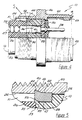
- Figure 3 is a partial cross sectional view schematic representation of the process of the tool 84 pressing in the annular insert retention gas tight seal.
- the receptacle shell 10 has an annular groove 22 inscribed within the interior surface 24 of the receptacle shell 10.
- the annular ring 44 having an annular ring exterior surface 49 and an annular ring interior surface 47, resides within the annular groove 22.
- the interior surface 47 of the annular ring 44 is forced against the first 26 and second 28 inserts of the receptacle connector, while the exterior surface 49 of the ring 44 presses against the interior surface 24 of the receptacle shell 10 within the groove 22.
- F in the range of approx.
- Figure 4 is a schematic representation partial cross sectional view of the receptacle connector while Figure 5 is an enlarged view of the annular ring 46 forming the seal.
- the receptacle shell 10 has an annular groove 22 inscribed within the interior surface 24 thereof.
- An annular ring 44 is positioned between the interior surface 24 of the receptacle shell 10 and the exterior surface of insert 28.
- the top 16 of the first insert 26 has a hole 27 operable to receive an electrical wire (not shown here) having a contact pin 38 electrically connected to its leading end and which would have been inserted through the first insert cavity 32 and second insert cavity 34. Wires terminated with a soldered connection are terminated before the terminals are assembled to the inserts.
- the pin 38 is held in place within the third insert cavity 36 by a clip retaining means 41.
- the annular sealing means 48 at the bottom 18 of the receptacle engages the annular sealing means 55 of the plug ( Figure 7) forming a seal.
- Conductor wires are clamped after insertion by reduced diameter portions of cavity portions 32 for mechanical vibration and seal support benefits.
- the second threaded 42 means of the receptacle shell 10 and key 43 with a corresponding keyway of plug shell 12 serve to align the receptacle shell 10 with the plug shell 12.
- the annular ring 44 provides a seal within the opening 51 between the interior surface 24 of the receptacle shell 10 and the inserts 26,28.
- Figure 5 is a partial cross sectional view schematic representation of the pressed-in receptacle annular ring of Figure 4.
- the receptacle shell 10 has inscribed surface groove 22 wherein annular ring 44 is pressed.
- the open area 51 within the space formed by the interior surface 24 of the receptacle shell 10 and the insert 26 is blocked by the top 53 of the ring 44.
- the pressing of the ring 44 results in the compression of ring 44 forwardly against an enlarged diameter portion of insert 28, and of the interior surface 47 of the ring against exterior surface of the insert, and the exterior surface 49 against the bottom surface of annular groove 22.
- the compressed ring 44 provides support to the inserts where they mate at bonded interface 39 wherein the bottom 33 of the first insert 26 is joined to the top 35 of the second insert 28.
- the annular ring 44 is shown in relation to the exterior surface 50 of the receptacle shell 10 and first threaded means 40.
- Figure 6 is a schematic representation partial cross sectional view of the connector plug and coupling nut having insert view 7.
- the plug shell 12 has a top 52 and bottom 54.
- the coupling nut 14 is shown matingly engaged to the plug shell 12 by coupling nut retaining ring 80 and the receptacle second threaded means 42 ( Figure 4).
- Electrical wires (not shown) are operable to enter the second plug insert cavity 74 and be electrically connected to the female electrical contact 102 having either crimped or soldered terminations.
- a receptacle connector having metal pins 38 when matingly engaged with the plug connector transmit electrical signals from the pins 38 which enter the plug through holes 101 to the female contacts 102 within the first insert cavity 72.
- the gas tight seal within the plug connector is accomplished by first inscribing an annular groove 62 within the interior surface 58 of the plug shell 12.
- An annular plug ring 64 of a soft metal is then slidably interfit around the second insert means 70 and the interior surface 58 of the plug shell.
- a metal tool similar to tool 84 of Figure 2, impresses and compresses the annular plug ring 64 within the inscribed groove 62 providing mechanical support for the bonded-together first and second inserts 68,70.
- An O-ring 95 serves as a secondary seal when it is placed between the coupling nut 14 and plug within the annular side flange 60. It is an industry standard in some connectors to bond the O-ring 95 within the front of the shell of the plug connector.
- FIG. 7 is a schematic representation partial cross sectional view of the secondary seal between the plug connector of Fig. 6 and the receptable connector.
- the plug shell 12 with exterior 56 has an annular side flange 60 of the plug shell 12.
- the O-ring 95 fits within the flange 60 between the annular sealing edge 48 of the receptacle shell 10, sealing between the interior of the front of receptacle shell 10 and the exterior of the front of plug shell 12.
- the interior 58 of the plug shell 12 rests against the first 68 and second 70 insert means due to a force fitting relationship.
- This O-ring 95 serves as a secondary seal for the open area 110 between the mating surfaces of the receptacle shell 10 and plug shell 12.
- a method of providing this gas tight seal for the retainage of the insert includes: the grooving of the interior surface of the receptacle and plug shells, the insertion of a separate annular ring of aluminum or other annealed soft metal around the insert, placing around the inserts within the receptacle and plug rings a tool, compressing and collapsing the soft annealed ring into a position surrounding the insert providing a gas tight free seal to support the insert.
- the completed seal appears as one complete unit of the ring and housing.
Description
- The present invention relates to an insert retention, gas tight seal for an electrical connector and more particularly to a solid metal annular ring gas tight seal which becomes an integral part of the connector housing for both the receptacle and the plug.
- Expanding ring retainers for use in electrical connectors which provide limited movement and limited vibration deterioration of the connector insert are known.
- U.S. Patent No. 4,099,323, issued July 11, 1978 to A.J. Bouvier, entitled "Method of Making Electrical Connector", describes an electrical connector having a ribbon-like laminate deformed in the space between the connector shell and an insert member and between the connector shell and a wafer to maintain the insert member and the wafer assembled one to another within the shell.
- As disclosed in the Bouvier patent, this insert member is a thin laminate which can be mechanically deformed until it substantially fills the space between the shell and the insert. The laminate member is made of a matrix of screen-like material, for example a wire screen, impregnated with an epoxy or other thermal setting material. Specific embodiments of the Bouvier device comprise a matrix material having a bronze screen.
- U.S. Patent No. 4,019,799, issued April 26, 1977 also to A.J. Bouvier, entitled "Electrical Connector", discloses wrapping a deformable laminate around the members within an electrical connector housing and inserting the assembled members with the laminate into a shell thereby affixing the connector inserts immovable in this application. In the second patent to Bouvier, the laminate is a screen-like material impregnated with an epoxy. The Bouvier device describes a laminate deformed wherein it substantially fills the space including an annular groove within the insert of the housing. The laminate is deformed prior to the insertion of terminals using a pressure tool.
- U.S. Patent No. 4,703,987 issued November 3, 1987 to David O. Gallusser, et al. entitled "Apparatus and Method for Retaining an Insert in an Electrical Connector", describes a deformable plastic strip longitudinally deformed and slotted within a longitudinal column of an electrical connector. The Gallusser, et al. patent discloses an annular groove on the inner wall and the dielectric insert having an outer periphery disposed within the connector shell so that an annular passageway is provided between the shell and the insert thereby providing a retention arrangement for retaining the insert in the shell.
- Further, this insert retention member in the Gallusser, et al. patent, incorporates an insert tool to insert and maintain the insert between the connector shell and the dielectric insert. The Gallusser, et al. device incorporates the use of a dielectric material such as a plastic because of the conductive path which occurs between the insert assembly and the shell when a copper mesh epoxy laminate or metal ring staking is used.
- Finally, U.S. patent No. 4,682,832, entitled "Retaining an Insert in an Electrical Connector", issued July 28, 1987 to Stephen Punako, et al., discloses a tubular sleeve of deformable plastic longitudinally slotted defining longitudinal columns having leading edges. The annular passageway formed between the connector insert and shell allows the longitudinal columns to collapse accordion style thereby radially wedging and locking in the columns in the passage and retaining the insert within the shell.
- In the Punako, et al. device, an electrical connector having a metal shell includes an annular groove within the interior wall of the shell, wherein the dielectric insert has an outer periphery disposed within the shell so that there is an annular passageway between the shell and the insert.
- The Punako, et al. retention arrangement includes a thermoplastic material retention member longitudinally slotted along its front face providing a plurality of axially weakened columns that terminate in a leading edge such that each column can curl back 180° upon themselves to lock the forward end portion of each respective column. Each axially weakened column is forward of the respective column medium portion such that each column is weakened to collapsibly fold and stack in accordion-like fashion forming radial folds. These columns are then curled and folded after the leading edges have engaged in an axial wall of the annular groove at the end of the passageway, and the curled folded column portions interface and wedge in the passageway around the annular passageway thereby retaining the insert within the shell.
- It is a long held industry problem of the insulating insert moving within the electrical connector, thereby causing a deterioration of the insert and a loss of electrical interface connection due to the heavy vibration of equipment supporting the connectors.
- Connectors which are necessary for use in heavy construction, for example, require a retaining system which can maintain the integrity of the connector insert without movement because movement of the inserts or deterioration of the inserts results in a misalignment of the fully mated connector.
- This invention provides an insert retention, gas tight seal in an electrical connector as defined in claim 1. According to an embodiment of the invention, the electrical connector has a housing including: a receptacle, a plug and a coupling nut, wherein the receptacle and plug each have an insulating insert which resides within the electrical connector housing or shell. Annular grooves are inscribed upon the interior surface of the electrical connector housing. Soft annealed metal cylindrical rings are inserted within the electrical connector housing for the receptacle and plug around the inserts, specifically within the annular grooves.
- As an added and more specific feature, there is provided a cylindrical tool operable to, under high pressure, collapse and expand the soft annular metal cylindrical rings within the annular groove thereby providing a gas tight seal.
- The present invention, an insert retention gas tight seal for an electrical connector, solves the problem of the vibrational deterioration of the insulating insert within an electrical connector as used in the construction industry for connectors subjected to high vibration.
- Further, the invention provides an electrical connector insert retention system that can be provided in a high vibrational environmentally destructive arena guaranteeing the continued mating of the receptacle and plug without receptacle and plug insert degradation.
- A method of providing an insert retention gas tight seal in an electrical connector is defined in claim 3.
- The invention will now be described by way of example with reference to the accompanying drawings in which:
- FIGURE 1 is a schematic representation exploded cross sectional view of a connector receptacle, plug and coupling nut having an insert retention, gas tight seal;
- FIGURE 2 is a schematic representation exploded orthogonal view of a tool pressing the insert retention receptacle annular ring into the annular groove;
- FIGURE 3 is a schematic representation partial cross sectional view of the beveled edge of the tool pressing in the insert retainer annular ring;
- FIGURE 4 is a schematic representation partial cross sectional view of the connector receptacle having
insert view 5; - FIGURE 5 is a schematic representation partial cross sectional view of the pressed in insert retainer annular ring;
- FIGURE 6 is a schematic representation partial cross sectional view of the connector plug and coupling nut having insert
view 7; and - FIGURE 7 is a schematic representation partial cross sectional view of the secondary seal between the connector plug and the coupling nut of Figure 6.
- The invention, an insert retention gas tight seal for an electrical connector, comprises a standard electrical connector having a receptacle, plug and coupling nut which has annular grooves inscribed within the interior walls of the receptacle and plug shells. The inserts for the receptacle and plug are inserted by hand into the respective shells, and an annular aluminum or other soft metal annular ring is inserted surrounding the inserts between the interior surfaces of the receptacle shell and plug shell and the exterior surfaces of the inserts.
- A beveled cylindrical tool is pressed against the soft metal annular rings under high pressure collapsing and expanding the soft metal into the inscribed grooves of the receptacle and plug shell interior surfaces. The combination of the inscribed grooves, the soft metal impressed within the grooves, and the receptacle and plug shell interior surfaces create a gas tight seal surrounding the inserts and a stable support for the inserts when they are subjected to high vibration.
- Figure 1, is a schematic representation exploded cross sectional view of a
connector 5 having a receptacle and a plug, each incorporating an insert retention, gas tight seal with the receptacle and plug connectors to be secured together with acoupling nut 14. Theshell 10 of the receptacle has atop 16 andbottom 18 as viewed in Figure 1. Protruding from thetop 16 of thereceptacle shell 10 is thefirst receptacle insert 26. Thisinsert 26 has a plurality of orifices 27 adapted to receive wires (not shown) connected to thepins 38 as is well known in the art. First receptacle insert 26 rests upon asecond receptacle insert 28. Theinterior surface 24 of the receptacle shell is inscribed by anannular groove 22 at a point upon theinterior surface 24 where thefirst insert 26 andsecond insert 28 are matingly joined. An annularinsert retaining ring 44 is mounted within the inscribedgroove 22. The annularinsert retaining ring 44 of this example is soft annealed aluminum. A third receptacle insert 30 rests below and is joined with thesecond receptacle insert 28. Electricallyconductive metal pins 38 protrude from the third receptacle insert 30. Thesemetal pins 38 are operable to enter theorifices 101 of the plug and mate with female contacts therein. - Wires (not shown) extend through the first receptacle insert 26 through orifices 27 and through the first
receptacle insert cavities 32, secondreceptacle insert cavities 34 and third receptacle insert cavities 36 where their ends interconnect with themetal pins 38. Awall mounting flange 46 having two mounting orifices 130,130′ is operable to facilitate the wall mounting of the receptacle to a fixed planar surface. The threads so formed on theinterior surface 78 of thecoupling nut 14 engage thethreads 42 of thereceptacle shell 10 to mechanically and electrically secure together the plug and receptacle. The beveled inner edge ofbottom 18 defines an annular sealing means 48 of the receptacle shell which matingly engages theannular side flange 60 of the plug shell when the receptacle and plug connectors are mated. O-ring 95 serves as a primary seal between thereceptacle shell 10 andplug shell 12. - As shown in Figure 1, during connector mating, the
top 52 of theplug shell 12 matingly interfits within thebottom 18 of thereceptacle shell 10 such that the exterior surface of theplug 56 slidably interfits within theinterior surface 24 of thereceptacle shell 10 withkey 43 extending along a corresponding keyway of theplug shell 12. Themetal pins 38 of the receptacle connector enter theholes 101 within the plug first insert means 68 and pass into the plugfirst insert cavities 72 to engage female electrical contacts (see Figure 6), residing therein. Electrical wires (not shown) fastened to the female electrical contacts pass through the plugsecond insert 70 and through plugsecond insert cavities 74. Theplug 12 has itsinterior surface 58 inscribed with anannular groove 62. Anannular retaining ring 64 for the plug provides insert 68 stability, and a gas tight seal for the plug. Thecoupling nut 14 lockingly engages theplug shell 12 andreceptacle shell 10 when itsexterior surface 76 is turned with threads 80 ofring 14 engaging withthreads 42 ofreceptacle shell 10. - Figure 2 is a schematic representation exploded orthogonal view of the tool pressing in the receptacle annular retaining ring around the first insert of the receptacle. This process would be identical for the pressing of the annular ring in the plug shell 12 (not shown here). In the example of Figure 2, the
tool 84 having a flat top 86 which can be subjected to pressure, ashank 88 ending with abeveled edge 90 slidingly interfits between the outer surface offirst insert 26 and theinterior surface 24 offirst receptacle shell 10.Annular ring 44 rests within an inscribedgroove 22 within theinterior surface 24 of thereceptacle shell 10. This inscribedgroove 22 is positioned upon theinterior surface 24 of thereceptacle shell 10 between thefirst insert 26 and thesecond insert 28. After thetool 84 is placed upon theannular ring 44 it is subjected to a force of between approx. 600 and 1100 KN·m⁻² (100 to 150 psi). This force compresses the annular ring within the inscribedgroove 22. This gas tight seal formed by theannular ring 44 is an integral part of theinterior surface 24 of thereceptacle shell 10. The gas tight seal also provides increased structural support to theinserts - Figure 3 is a partial cross sectional view schematic representation of the process of the
tool 84 pressing in the annular insert retention gas tight seal. Specifically, thereceptacle shell 10 has anannular groove 22 inscribed within theinterior surface 24 of thereceptacle shell 10. Theannular ring 44 having an annularring exterior surface 49 and an annular ringinterior surface 47, resides within theannular groove 22. Theinterior surface 47 of theannular ring 44 is forced against the first 26 and second 28 inserts of the receptacle connector, while theexterior surface 49 of thering 44 presses against theinterior surface 24 of thereceptacle shell 10 within thegroove 22. When a force, F, in the range of approx. 600 to 1100 KN·m⁻² (100 to 150 psi) is applied to theannular ring 44 through thebeveled edge 90 of thetool 84, theannular ring 44 and the receptacle become one. The tip 45 of theannular ring 44 is forced within thegroove 22 by thebeveled edge 90 of thetool 84, facilitating a gas tight seal at thebonding point 39 of the first 26 and second 28 inserts; specifically, where the bottom 33 of thefirst insert 26 rests upon the top 35 of thesecond insert 28. First and second inserts of both the plug and receptacle connector are bonded together.Member 30 is bonded to the front of the forward insert. - Figure 4 is a schematic representation partial cross sectional view of the receptacle connector while Figure 5 is an enlarged view of the
annular ring 46 forming the seal. As can be seen in Figure 4, thereceptacle shell 10 has anannular groove 22 inscribed within theinterior surface 24 thereof. Anannular ring 44 is positioned between theinterior surface 24 of thereceptacle shell 10 and the exterior surface ofinsert 28. The top 16 of thefirst insert 26 has a hole 27 operable to receive an electrical wire (not shown here) having acontact pin 38 electrically connected to its leading end and which would have been inserted through thefirst insert cavity 32 andsecond insert cavity 34. Wires terminated with a soldered connection are terminated before the terminals are assembled to the inserts. Thepin 38 is held in place within the third insert cavity 36 by a clip retaining means 41. As shown in Figure 4, during connector mating the annular sealing means 48 at the bottom 18 of the receptacle engages the annular sealing means 55 of the plug (Figure 7) forming a seal. Conductor wires are clamped after insertion by reduced diameter portions ofcavity portions 32 for mechanical vibration and seal support benefits. The second threaded 42 means of thereceptacle shell 10 and key 43 with a corresponding keyway ofplug shell 12 serve to align thereceptacle shell 10 with theplug shell 12. Theannular ring 44 provides a seal within theopening 51 between theinterior surface 24 of thereceptacle shell 10 and theinserts - Figure 5 is a partial cross sectional view schematic representation of the pressed-in receptacle annular ring of Figure 4. The
receptacle shell 10 has inscribedsurface groove 22 whereinannular ring 44 is pressed. Theopen area 51 within the space formed by theinterior surface 24 of thereceptacle shell 10 and theinsert 26 is blocked by the top 53 of thering 44. The pressing of thering 44 results in the compression ofring 44 forwardly against an enlarged diameter portion ofinsert 28, and of theinterior surface 47 of the ring against exterior surface of the insert, and theexterior surface 49 against the bottom surface ofannular groove 22. The compressedring 44 provides support to the inserts where they mate at bondedinterface 39 wherein the bottom 33 of thefirst insert 26 is joined to the top 35 of thesecond insert 28. Theannular ring 44 is shown in relation to theexterior surface 50 of thereceptacle shell 10 and first threaded means 40. - Figure 6 is a schematic representation partial cross sectional view of the connector plug and coupling nut having
insert view 7. Theplug shell 12 has a top 52 and bottom 54. Thecoupling nut 14 is shown matingly engaged to theplug shell 12 by coupling nut retaining ring 80 and the receptacle second threaded means 42 (Figure 4). Electrical wires (not shown) are operable to enter the secondplug insert cavity 74 and be electrically connected to the femaleelectrical contact 102 having either crimped or soldered terminations. A receptacle connector havingmetal pins 38 when matingly engaged with the plug connector transmit electrical signals from thepins 38 which enter the plug throughholes 101 to thefemale contacts 102 within thefirst insert cavity 72. The gas tight seal within the plug connector is accomplished by first inscribing anannular groove 62 within theinterior surface 58 of theplug shell 12. Anannular plug ring 64 of a soft metal is then slidably interfit around the second insert means 70 and theinterior surface 58 of the plug shell. A metal tool, similar totool 84 of Figure 2, impresses and compresses theannular plug ring 64 within the inscribedgroove 62 providing mechanical support for the bonded-together first andsecond inserts ring 95 serves as a secondary seal when it is placed between thecoupling nut 14 and plug within theannular side flange 60. It is an industry standard in some connectors to bond the O-ring 95 within the front of the shell of the plug connector. - Figure 7 is a schematic representation partial cross sectional view of the secondary seal between the plug connector of Fig. 6 and the receptable connector. The
plug shell 12 withexterior 56 has anannular side flange 60 of theplug shell 12. The O-ring 95 fits within theflange 60 between theannular sealing edge 48 of thereceptacle shell 10, sealing between the interior of the front ofreceptacle shell 10 and the exterior of the front ofplug shell 12. The interior 58 of theplug shell 12 rests against the first 68 and second 70 insert means due to a force fitting relationship. This O-ring 95 serves as a secondary seal for theopen area 110 between the mating surfaces of thereceptacle shell 10 and plugshell 12. - Whenever the inserts as shown in these figures are moved, or the insert retaining rings are under tension through vibrational forces, the work-hardened metal of the annular rings provide a fully formed connector support structure which gives the inserts increased mechanical support.
- A method of providing this gas tight seal for the retainage of the insert, includes: the grooving of the interior surface of the receptacle and plug shells, the insertion of a separate annular ring of aluminum or other annealed soft metal around the insert, placing around the inserts within the receptacle and plug rings a tool, compressing and collapsing the soft annealed ring into a position surrounding the insert providing a gas tight free seal to support the insert. The completed seal appears as one complete unit of the ring and housing.
- Connectors of industrial quality having high durability and structural stability are developed using this system.
- While particular embodiments of the invention have been shown and described, it will be obvious to those skilled in the art that changes and modifications may be made without departing from the invention as defined in the appended claims.
Claims (5)
- An insert retention means in an electrical connector (5) comprising a shell member (10,12) and an insert member (28,68), said shell member (10,12) having an annular groove (22,62) inscribed within the interior surface (24,58) of the shell member (10,12), and a retention ring (44,64) disposed about said insert member (28,68) associated with said annular groove (22,62), characterized in that:
an enlarged diameter portion of said insert member (28,68) is disposed just forwardly of said annular groove (22,62) and defining a rearwardly facing surface, and
said annular ring (44,64) is a continuous member of soft metal and is disposed rearwardly of and against said rearwardly facing surface, and said annular ring (44,64) is plastically deformed outwardly into said annular groove (22,62) and compressed against said interior surface (24) of said shell member (10,12) and against said rearwardly facing surface and exterior surface portion (56) of said insert member (28,68) to form a gas tight seal between said insert member (28,68) and said shell member (10,12). - An insert retention means as set forth in claim 1 further characterized in that said annular ring (44,64) is aluminum.
- A method of providing an insert retention system in an electrical connector (5) of the type having an insert (28,68) within a shell (10,12) and including a retention ring (44,64), comprising the steps of:
grooving an interior surface (24,58) of said shell (10,12) at a selected location (22,62) rearwardly of an enlarged diameter portion of said insert (28,68);
inserting a soft metal cylindrical ring (44,64) within said shell (10,12) and alongside said insert (28,68) rearwardly and against a rearwardly facing surface defined by said enlarged diameter insert portion and radially within said groove location (22,62); and
impacting and plastically deforming said soft metal cylindrical ring (44,64) at a rearwardly facing edge thereof with a hard metal bevel-edged tool (84) from rearwardly of said connector (5) such that said ring (44,64) is collapsed and compressed under a high force to be compressed against said rearwardly facing surface and said exterior surface (56) of said insert (28,68) and outwardly into said groove (22,62) and against said interior surface (24,58) of said shell (10,12), defining a gas tight seal and assuredly retaining said insert (28,68) in said shell (10,12). - The method as set forth in claim 3 or 4 further characterized in that said high force is approximately in the range of 600 to 1100 KN·m⁻² (100 to 150 psi).
- The method as set forth in claim 3 further characterized in that said bevel-edged tool (84) is cylindrical and inserted between an annular gap between said exterior surface (56) of said insert (28,68) and said interior surface (24,58) of said shell (10,12).
Applications Claiming Priority (2)
| Application Number | Priority Date | Filing Date | Title |
|---|---|---|---|
| US59507490A | 1990-10-09 | 1990-10-09 | |
| US595074 | 1990-10-09 |
Publications (3)
| Publication Number | Publication Date |
|---|---|
| EP0480337A2 EP0480337A2 (en) | 1992-04-15 |
| EP0480337A3 EP0480337A3 (en) | 1992-08-19 |
| EP0480337B1 true EP0480337B1 (en) | 1995-08-09 |
Family
ID=24381620
Family Applications (1)
| Application Number | Title | Priority Date | Filing Date |
|---|---|---|---|
| EP91116977A Expired - Lifetime EP0480337B1 (en) | 1990-10-09 | 1991-10-04 | Insert retention gas tight seal for an electrical connector and method of making same |
Country Status (4)
| Country | Link |
|---|---|
| US (2) | US5295866A (en) |
| EP (1) | EP0480337B1 (en) |
| JP (1) | JPH04262377A (en) |
| DE (1) | DE69111962T2 (en) |
Families Citing this family (22)
| Publication number | Priority date | Publication date | Assignee | Title |
|---|---|---|---|---|
| US5399095A (en) * | 1991-03-26 | 1995-03-21 | Square D Company | Variable phase positioning device |
| DE4418259C1 (en) * | 1994-05-25 | 1995-08-24 | Hirschmann Richard Gmbh Co | Multipole electrical connector for stranded cables |
| US5980317A (en) * | 1998-03-13 | 1999-11-09 | Geo Space Corporation | Repairable electrical geophysical connector |
| US6319073B1 (en) * | 1999-12-16 | 2001-11-20 | Amphenol Corporation | Hybrid submarine streamer connector |
| JP2001257028A (en) * | 2000-03-10 | 2001-09-21 | Yazaki Corp | Coupling structure of connector |
| EP1180823B1 (en) * | 2000-08-09 | 2004-06-02 | Phoenix Contact GmbH & Co. KG | Cable-connection or cable-joint device |
| FR2839815B1 (en) * | 2002-05-15 | 2004-06-25 | Positronic Ind | METHOD FOR SEALING COAXIAL TYPE ROOF CONNECTOR CONNECTOR CONTACTS, ADAPTED COAXIAL CONTACT AND CONNECTOR THUS OBTAINED |
| US7144268B2 (en) * | 2003-08-19 | 2006-12-05 | Spacelabs Medical, Inc. | Latching medical patient parameter safety connector and method |
| US7165980B2 (en) * | 2004-05-13 | 2007-01-23 | Thomas & Betts International, Inc. | Conduit bushing with revolving lug |
| EP1628370B1 (en) * | 2004-08-20 | 2012-11-07 | Continental Automotive GmbH | Electrical connecting device |
| FR2879837B1 (en) * | 2004-12-16 | 2015-07-24 | Radiall Sa | ADAPTER FOR MULTICONTACT CONNECTOR AND SUCH CONNECTOR. |
| US7517258B1 (en) * | 2006-01-31 | 2009-04-14 | H-Tech, Llc | Hermetically sealed coaxial type feed-through RF Connector |
| US20080139030A1 (en) * | 2006-12-08 | 2008-06-12 | Scully Signal Company | Electrical socket assembly for tanker truck overfill prevention system |
| US7794254B2 (en) | 2007-04-30 | 2010-09-14 | Tronic Limited | Submersible electrical connector |
| GB0708362D0 (en) * | 2007-04-30 | 2007-06-06 | Tronic Ltd | Connector |
| JP5242311B2 (en) * | 2008-09-22 | 2013-07-24 | 三菱電線工業株式会社 | Seal insertion method and apparatus |
| US8035030B2 (en) * | 2009-04-13 | 2011-10-11 | Robert Bosch Gmbh | Hermetically sealed electrical connection assembly |
| PL2330706T3 (en) * | 2009-12-03 | 2017-09-29 | CommScope Connectivity Belgium BVBA | Gel sealing device |
| EP2330707A1 (en) * | 2009-12-03 | 2011-06-08 | Tyco Electronics Raychem BVBA | Gel sealing device |
| AU2013286141B2 (en) | 2012-07-02 | 2017-03-30 | CommScope Connectivity Belgium BVBA | Cable sealing unit with multiple sealing modules |
| US9048584B2 (en) * | 2013-01-31 | 2015-06-02 | Tyco Electronics Corporation | Electrical connector system having an insulator holding terminals |
| JP6941270B2 (en) * | 2017-01-30 | 2021-09-29 | 住友電気工業株式会社 | Fluid sealing device and power cable line |
Family Cites Families (30)
| Publication number | Priority date | Publication date | Assignee | Title |
|---|---|---|---|---|
| US913595A (en) * | 1908-10-22 | 1909-02-23 | Fred H Weinhauer | Spark-plug. |
| US2466057A (en) * | 1947-02-18 | 1949-04-05 | Somma Raymond | Combined tube connector and tube flarer |
| US2687906A (en) * | 1949-01-26 | 1954-08-31 | Wagner Electric Corp | Swaged type metallic pipe fitting |
| US2989784A (en) * | 1957-10-04 | 1961-06-27 | Bell Telephone Labor Inc | Method of forming a plug of high melting point plastic bonded to a low melting point plastic |
| FR1206968A (en) * | 1958-05-24 | 1960-02-12 | Connection of electrical conductors | |
| DE1273032B (en) * | 1963-11-30 | 1968-07-18 | Rohde & Schwarz | Plug coupling for coaxial lines |
| US3373243A (en) * | 1966-06-06 | 1968-03-12 | Bendix Corp | Electrical multiconductor cable connecting assembly |
| GB1183819A (en) * | 1966-09-23 | 1970-03-11 | British Insulated Callenders | Improvements in or relating to Electric Cable Terminations. |
| US3529856A (en) * | 1969-01-08 | 1970-09-22 | Dumont Aviat Associates | Coupling and method of forming same |
| US3646502A (en) * | 1970-08-24 | 1972-02-29 | Bunker Ramo | Connector element and method for element assembly |
| US3644874A (en) * | 1970-10-07 | 1972-02-22 | Bunker Ramo | Connector element and method for element assembly |
| US3810073A (en) * | 1973-01-26 | 1974-05-07 | Omni Spectra Inc | Connector locking mechanism |
| DE2317700A1 (en) * | 1973-04-09 | 1974-10-24 | Norddeutsche Seekabelwerke Ag | PRESSURE WATERPROOF CONNECTION FOR ELECTRIC CABLES |
| US3836700A (en) * | 1973-12-06 | 1974-09-17 | Alco Standard Corp | Conduit coupling |
| US3888522A (en) * | 1974-04-01 | 1975-06-10 | Weatherhead Co | Flareless fitting |
| US3917373A (en) * | 1974-06-05 | 1975-11-04 | Bunker Ramo | Coupling ring assembly |
| US4019799A (en) * | 1976-02-11 | 1977-04-26 | The Bendix Corporation | Electrical connector |
| US4074927A (en) * | 1976-07-26 | 1978-02-21 | Automation Industries, Inc. | Electrical connector with insert member retaining means |
| US4059330A (en) * | 1976-08-09 | 1977-11-22 | John Schroeder | Solderless prong connector for coaxial cable |
| US4296992A (en) * | 1977-09-26 | 1981-10-27 | Bunker Ramo Corporation | Electrical connector assembly |
| US4389081A (en) * | 1980-11-14 | 1983-06-21 | The Bendix Corporation | Electrical connector coupling ring |
| US4413875A (en) * | 1981-09-23 | 1983-11-08 | Matrix Science Corporation | Connector retaining apparatus |
| US4544224A (en) * | 1982-09-07 | 1985-10-01 | International Telephone & Telegraph Corp. | Self-locking electrical connector |
| US4647086A (en) * | 1983-12-27 | 1987-03-03 | Brass-Craft Manufacturing Company | Tube coupling |
| FR2582870B1 (en) * | 1985-06-04 | 1987-07-24 | Socapex | ELECTRICAL CONNECTOR WITH DEFORMABLE RETENTION ELEMENT AND METHOD FOR ASSEMBLING SUCH A CONNECTOR |
| US4703987A (en) * | 1985-09-27 | 1987-11-03 | Amphenol Corporation | Apparatus and method for retaining an insert in an electrical connector |
| US4682832A (en) * | 1985-09-27 | 1987-07-28 | Allied Corporation | Retaining an insert in an electrical connector |
| US4810209A (en) * | 1987-05-28 | 1989-03-07 | Amphenol Corporation | Pressurized electrical connector and method of assembly |
| US4871328A (en) * | 1988-09-14 | 1989-10-03 | Simmonds Precision Products, Inc. | Hermetically sealing connector and method of use thereof |
| US4920643A (en) * | 1988-09-26 | 1990-05-01 | Microwave Development Laboratories | Method of assembling electrical connector |
-
1991
- 1991-10-04 DE DE69111962T patent/DE69111962T2/en not_active Expired - Fee Related
- 1991-10-04 EP EP91116977A patent/EP0480337B1/en not_active Expired - Lifetime
- 1991-10-09 JP JP3289475A patent/JPH04262377A/en active Pending
-
1992
- 1992-01-13 US US07/821,345 patent/US5295866A/en not_active Expired - Fee Related
-
1994
- 1994-03-22 US US08/216,005 patent/US5425171A/en not_active Expired - Fee Related
Also Published As
| Publication number | Publication date |
|---|---|
| EP0480337A3 (en) | 1992-08-19 |
| JPH04262377A (en) | 1992-09-17 |
| US5425171A (en) | 1995-06-20 |
| US5295866A (en) | 1994-03-22 |
| DE69111962D1 (en) | 1995-09-14 |
| EP0480337A2 (en) | 1992-04-15 |
| DE69111962T2 (en) | 1995-11-23 |
Similar Documents
| Publication | Publication Date | Title |
|---|---|---|
| EP0480337B1 (en) | Insert retention gas tight seal for an electrical connector and method of making same | |
| US5217392A (en) | Coaxial cable-to-cable splice connector | |
| US4280749A (en) | Socket and pin contacts for coaxial cable | |
| EP2556565B1 (en) | Electromagnetic shielding device | |
| JP2921641B2 (en) | Waterproof connector | |
| US4150866A (en) | Environmentally sealed connector | |
| KR101248696B1 (en) | Connector with outer conductor axial compression connection and method of manufacture | |
| JPH07111889B2 (en) | Method of retaining insert in electrical connector assembly and shell | |
| US5695357A (en) | Cable connector kit, cable connector assembly and related method | |
| US5482480A (en) | Connector terminal | |
| KR100530580B1 (en) | Connector assembly and cable grounding method | |
| JP3032783B2 (en) | Die mold for conductor crimping and crimping method | |
| US3409864A (en) | Sealed electrical connecting device | |
| US4991289A (en) | Crimping die and crimped electrical connection therefrom | |
| US3894785A (en) | Connector | |
| EP0560668B1 (en) | Repairable connector | |
| EP0026692A1 (en) | One piece electrical contact | |
| US4373262A (en) | Electrical contact with locking device | |
| JP2953961B2 (en) | Connector manufacturing method | |
| US6475035B1 (en) | Multipolar plug-in connection | |
| JPH09270282A (en) | Coaxial connector | |
| US4278313A (en) | Electrical contact with locking device | |
| EP0022627A1 (en) | Electrical connector for terminating coaxial electrical cable | |
| EP0435953A4 (en) | Method of assembling electrical connector | |
| US4752235A (en) | Electrical connector with deformable retention element and procedure for assembly of such a connector |
Legal Events
| Date | Code | Title | Description |
|---|---|---|---|
| PUAI | Public reference made under article 153(3) epc to a published international application that has entered the european phase |
Free format text: ORIGINAL CODE: 0009012 |
|
| AK | Designated contracting states |
Kind code of ref document: A2 Designated state(s): DE FR GB SE |
|
| PUAL | Search report despatched |
Free format text: ORIGINAL CODE: 0009013 |
|
| AK | Designated contracting states |
Kind code of ref document: A3 Designated state(s): DE FR GB SE |
|
| 17P | Request for examination filed |
Effective date: 19930217 |
|
| 17Q | First examination report despatched |
Effective date: 19940926 |
|
| GRAA | (expected) grant |
Free format text: ORIGINAL CODE: 0009210 |
|
| AK | Designated contracting states |
Kind code of ref document: B1 Designated state(s): DE FR GB SE |
|
| REF | Corresponds to: |
Ref document number: 69111962 Country of ref document: DE Date of ref document: 19950914 |
|
| ET | Fr: translation filed | ||
| PLBE | No opposition filed within time limit |
Free format text: ORIGINAL CODE: 0009261 |
|
| STAA | Information on the status of an ep patent application or granted ep patent |
Free format text: STATUS: NO OPPOSITION FILED WITHIN TIME LIMIT |
|
| 26N | No opposition filed | ||
| PGFP | Annual fee paid to national office [announced via postgrant information from national office to epo] |
Ref country code: SE Payment date: 19981007 Year of fee payment: 8 |
|
| PGFP | Annual fee paid to national office [announced via postgrant information from national office to epo] |
Ref country code: DE Payment date: 19981028 Year of fee payment: 8 |
|
| PG25 | Lapsed in a contracting state [announced via postgrant information from national office to epo] |
Ref country code: SE Free format text: THE PATENT HAS BEEN ANNULLED BY A DECISION OF A NATIONAL AUTHORITY Effective date: 19991030 |
|
| EUG | Se: european patent has lapsed |
Ref document number: 91116977.9 |
|
| PG25 | Lapsed in a contracting state [announced via postgrant information from national office to epo] |
Ref country code: DE Free format text: LAPSE BECAUSE OF NON-PAYMENT OF DUE FEES Effective date: 20000801 |
|
| PGFP | Annual fee paid to national office [announced via postgrant information from national office to epo] |
Ref country code: FR Payment date: 20011005 Year of fee payment: 11 |
|
| REG | Reference to a national code |
Ref country code: GB Ref legal event code: IF02 |
|
| PGFP | Annual fee paid to national office [announced via postgrant information from national office to epo] |
Ref country code: GB Payment date: 20020913 Year of fee payment: 12 |
|
| PG25 | Lapsed in a contracting state [announced via postgrant information from national office to epo] |
Ref country code: FR Free format text: LAPSE BECAUSE OF NON-PAYMENT OF DUE FEES Effective date: 20030630 |
|
| REG | Reference to a national code |
Ref country code: FR Ref legal event code: ST |
|
| PG25 | Lapsed in a contracting state [announced via postgrant information from national office to epo] |
Ref country code: GB Free format text: LAPSE BECAUSE OF NON-PAYMENT OF DUE FEES Effective date: 20031004 |
|
| GBPC | Gb: european patent ceased through non-payment of renewal fee |
Effective date: 20031004 |