EP0215326B1 - Spanngerät - Google Patents
Spanngerät Download PDFInfo
- Publication number
- EP0215326B1 EP0215326B1 EP86111577A EP86111577A EP0215326B1 EP 0215326 B1 EP0215326 B1 EP 0215326B1 EP 86111577 A EP86111577 A EP 86111577A EP 86111577 A EP86111577 A EP 86111577A EP 0215326 B1 EP0215326 B1 EP 0215326B1
- Authority
- EP
- European Patent Office
- Prior art keywords
- arm
- clamping jaw
- housing
- clamping
- tension rod
- Prior art date
- Legal status (The legal status is an assumption and is not a legal conclusion. Google has not performed a legal analysis and makes no representation as to the accuracy of the status listed.)
- Expired - Lifetime
Links
- 239000007787 solid Substances 0.000 claims 7
- 230000001154 acute effect Effects 0.000 claims 1
- 239000000126 substance Substances 0.000 claims 1
- 210000001364 upper extremity Anatomy 0.000 abstract 3
- 238000005096 rolling process Methods 0.000 abstract 1
- 238000006073 displacement reaction Methods 0.000 description 3
- 239000013013 elastic material Substances 0.000 description 2
- 238000004519 manufacturing process Methods 0.000 description 2
- 239000002184 metal Substances 0.000 description 2
- 230000036316 preload Effects 0.000 description 2
- 239000000725 suspension Substances 0.000 description 2
- 230000006835 compression Effects 0.000 description 1
- 238000007906 compression Methods 0.000 description 1
- 239000000356 contaminant Substances 0.000 description 1
- 230000006378 damage Effects 0.000 description 1
- 238000000034 method Methods 0.000 description 1
- 230000000149 penetrating effect Effects 0.000 description 1
- 230000000717 retained effect Effects 0.000 description 1
- 239000011343 solid material Substances 0.000 description 1
Images

Classifications
-
- B—PERFORMING OPERATIONS; TRANSPORTING
- B25—HAND TOOLS; PORTABLE POWER-DRIVEN TOOLS; MANIPULATORS
- B25B—TOOLS OR BENCH DEVICES NOT OTHERWISE PROVIDED FOR, FOR FASTENING, CONNECTING, DISENGAGING OR HOLDING
- B25B1/00—Vices
- B25B1/06—Arrangements for positively actuating jaws
- B25B1/10—Arrangements for positively actuating jaws using screws
- B25B1/103—Arrangements for positively actuating jaws using screws with one screw perpendicular to the jaw faces, e.g. a differential or telescopic screw
-
- B—PERFORMING OPERATIONS; TRANSPORTING
- B25—HAND TOOLS; PORTABLE POWER-DRIVEN TOOLS; MANIPULATORS
- B25B—TOOLS OR BENCH DEVICES NOT OTHERWISE PROVIDED FOR, FOR FASTENING, CONNECTING, DISENGAGING OR HOLDING
- B25B1/00—Vices
- B25B1/06—Arrangements for positively actuating jaws
- B25B1/10—Arrangements for positively actuating jaws using screws
- B25B1/12—Arrangements for positively actuating jaws using screws with provision for disengagement
-
- B—PERFORMING OPERATIONS; TRANSPORTING
- B25—HAND TOOLS; PORTABLE POWER-DRIVEN TOOLS; MANIPULATORS
- B25B—TOOLS OR BENCH DEVICES NOT OTHERWISE PROVIDED FOR, FOR FASTENING, CONNECTING, DISENGAGING OR HOLDING
- B25B1/00—Vices
- B25B1/24—Details, e.g. jaws of special shape, slideways
Definitions
- the invention relates to a tensioning device with the features of the introductory part of claim 1.
- the holding means consists of a pin that passes through an elongated hole of the tie rod and is attached with its ends in the housing.
- the tie rod can thus move to a limited extent in a plane parallel to the surface of the housing base in order to bring about self-adjustment in this plane.
- the tie rod deforms and its leg, which engages behind the fixed clamping jaw, is tilted slightly, which is associated with a downward movement component.
- the pin has no play in the vertical direction in the elongated hole of the tie rod, which is why the pin is exposed to very high shear forces in the gaps between tie rod and housing, which must lead to destruction at the latest after a certain operating time.
- the linear contact is produced by a rib which is convex in cross-section and a concave groove, and since the holding means does not allow any adjustment in the vertical direction, great precision must be ensured during manufacture.
- the object of the invention is to design a tensioning device of the type mentioned at the outset in such a way that it can be produced without a high degree of precision, and nevertheless at very high levels Clamping forces do not exert unacceptably high deformation forces on the holding means, so that even eccentric clamping with high clamping force is possible without deformation of the housing and the fixed clamping jaw.
- one leg of the tie rod in the region of the contact line has a nose which is convexly rounded in cross section, that a free space gap extending to the yoke of the tie rod is formed adjacent to the nose between the one leg and the fixed clamping jaw, and that the width of the clearance gap to the Glasankerjoch gradually increases.
- the rear surface of one leg can then be flat and the free space ensures that the tie rod leg only touches the fixed jaw along the contact line.
- a first embodiment of the invention forms the subject of claim 4.
- the bolts ensure a certain amount of displacement play in the trough-like recesses, so that the tie rod can move in all directions parallel to the clamping surface but also at an angle thereto and not only about the contact line but also perpendicular to it can pivot.
- the holding means which are preferably designed as sleeves, do not transmit any clamping forces during operation, but only serve to suspend the tie rod. According to both alternative solutions, a quick removal of the tie rod from the housing is guaranteed.
- threaded pieces on which the springs for the locking bolts are supported can be screwed so that the locking bolts can emerge from the trough-like recesses. Since the spring preload is only slight, the application of an axial pressure on the tie rod is sufficient to disengage the bolts from the trough-like recesses.
- the sleeves which are preferably made of rubber, remaining in the side walls of the fixed clamping jaw.
- a third alternative for the universally movable mounting of the tie rod is the subject of claims 7 and 8.
- the tie rod is permanently connected to the housing. It is also no longer necessary to remove the tie rod, since the gaps are poured out elastically, so that no metal chips and other contaminants could enter there.
- U-shaped tie rod 16 which has a first leg 18, a yoke 20 extending along the vise and a second leg 22 which has a threaded nut for a screw spindle 24 forms, one end of which engages behind a movable clamping jaw 26 which is displaceably guided on the housing 12 in longitudinal rails, is characterized in that the tie rod 16 is floatingly supported in the housing 12 by means of a three-point suspension is.
- the tie rod 16 with the two legs 18, 22 and the yoke 20 could form a one-piece component.
- the other leg 22 on the yoke 20 of the tie rod 16 is arranged so that it can be adjusted in stages by means of plug pins 28.
- the tie rod leg 18 has a trough-like depression 30 on each of its two side surfaces.
- the two depressions 30 are aligned transversely.
- the side walls of the fixed clamping jaw 14 have coaxial transverse bores 32, in each of which a locking bolt 34, a compression spring 36 and a threaded piece 38 are located.
- the threaded pieces 38 are screwed so far into the transverse bores 32 that the locking bolts 34 penetrate the trough-like recesses 30 of the tie rod leg 18 with a certain preload.
- the locking bolts 34 and the depressions 30 are designed with respect to one another in such a way that a relative displacement in all directions parallel to the side surfaces of the leg 18 is possible.
- the trough-like depressions 30 are, for example, conical, while the front surfaces of the locking bolts 34 are hemispherical in shape.
- the springs 36 seek to adjust the tie rod 16 so that the transverse axis containing the centers of the trough-like depressions 30 coincides with the transverse axis of the bores 32.
- the upper end of the left leg 18 facing the clamping zone is designed in the form of a nose 40 which is rounded in cross section.
- the nose 40 is adjoined by an oblique flat front surface 42 of the leg 18, which encloses an angle of approximately 5 ° with a plane 44 parallel to the clamping surface.
- the rear surface of the fixed clamping jaw 14 lies in the plane designated 44 in the clamping state, so that a gap 48 forms below the nose 40, which gradually widens towards the yoke 20 of the tie rod 16.
- the leg 18 of the tie rod 16 is made of solid material.
- the yoke 20, however, has a U-shaped cross section, in which the other leg 22 engages.
- the cross-sectional contour of the leg 18 is the same over the entire tie rod width.
- the trough-like depressions 30 in the leg 18 and the bores 32 in the fixed clamping jaw 14 are arranged such that the nose 40 roughly touches the rear surface 46 of the fixed clamping jaw with mutual transverse alignment.
- the tie rod 16 automatically aligns itself in such a way that that the locking bolts 34 shift in the trough-like recesses 30 such that a continuous contact of the nose 40 on the rear surface 46 of the fixed clamping jaw 14 theoretically takes place along a line of contact.
- the tie rod deforms and the nose 40 rolls on the rear surface 46, but line contact is still retained.
- FIG. 5 illustrates an alternative to the floating mounting of the tie rod leg 18.
- the side walls of the fixed clamping jaw 14 have transversely aligned bores 50, into which elastically deformable sleeves 52 are inserted.
- the leg 18 has a coaxial bore with an inner diameter equal to that of the elastic sleeves 52.
- a plug pin 54 passes through the bore of the leg 18 and the elastic sleeves 52.
- FIGURES 6 and 7 illustrate a third alternative to the floating mounting of the tie rod 16.
- the tie rod 16 is connected to the housing 12 on the bottom side and on both side surfaces over its entire length by means of elastic layers 56, 58. I.e. the gaps formed between tie rod 16 and housing are filled with elastic material.
- the elastic material ensures a self-adjustment of the tie rod 16 during the tensioning process and at the same time prevents metal chips from penetrating into the gaps. An additional mechanical mounting of the tie rod 16 on the housing 12 is thus eliminated.
Landscapes
- Engineering & Computer Science (AREA)
- Mechanical Engineering (AREA)
- Gripping Jigs, Holding Jigs, And Positioning Jigs (AREA)
- Clamps And Clips (AREA)
- Jigs For Machine Tools (AREA)
- Electrical Discharge Machining, Electrochemical Machining, And Combined Machining (AREA)
Description
- Die Erfindung betrifft ein Spanngerät, mit den Merkmalen des Einleitungsteils von Patentanspruch 1.
- Ein derartiges Spanngerät ist aus der GB-A-1,181,398 bekannt. Das Haltemittel besteht aus einem Stift, der ein Langloch des Zugankers durchsetzt und mit seinen Enden im Gehäuse befestigt ist. Der Zuganker kann sich somit in einer zur Gehäusebodenfläche parallelen Ebene begrenzt verlagern, um in dieser Ebene eine Selbsteinstellung zu bewirken. Bei hohen Spannkräften verformt sich jedoch der Zuganker und sein die feste Spannbacke hintergreifender Schenkel wird leicht schräg gestellt, was mit einer abwärts gerichteten Bewegungskomponente verbunden ist. Der Stift hat in dem Langloch des Zugankers in lotrechter Richtung kein Spiel, weswegen der Stift in den Spalten zwischen Zuganker und Gehäuse sehr hohen Scherkräften ausgesetzt ist, die spätestens nach einer gewissen Betriebszeit zur Zerstörung führen müssen. Außerdem wird der linienförmige Kontakt durch eine im Querschnitt konvex gewölbte Rippe und eine konkave Nut erzeugt, und da das Haltemittel in lotrechter Richtung keine Verstellung erlaubt, muß bei Herstellung auf hohe Präzision geachtet werden.
- Aufgabe der Erfindung ist es, ein Spanngerät der eingangs genannten Art so auszubilden, daß es ohne hohen Präzisionsaufwand herstellbar ist, und gleichwohl auch bei sehr hohen Spannkräften keine unzulässig hohen Verformungskräfte auf das Haltemittel ausübt, so daß sogar ein außermittiges Spannen mit hoher Spannkraft ohne Verformung des Gehäuses und der festen Spannbacke möglich ist.
- Diese Aufgabe wird bei einem Spanngerät mit den Merkmalen des Einleitungsteils von Patentanspruch 1 durch dessen Kennzeichnungsmerkmale gelöst.
- Dank der Erfindung wird eine allseitige Beweglichkeit des Zugankers im Gehäuse, also auch in lotrechter Richtung und winklig dazu gewährleistet, sodß sich der Zuganker bei allen Einspannstellungen selbsttätig ausrichtet und keinerlei Verformungskräfte auf die feste Spannbacke sowie keine plastischen Deformationen auf das Haltemittel ausübt, das aufgrund seiner Elastizität eine beliebige Verlagerung des Zugankers im Rahmen der Selbsteinstellung sicherstellt.
- Eine Ausgestaltung der Erfindung besteht darin, daß der eine Schenkel des Zugankers im Bereich der Kontaktlinie eine im Querschnitt konvex gerundete Nase aufweist, daß angrenzend an die Nase zwischen dem einen Schenkel und der festen Spannbacke ein bis zum Joch des Zugankers reichender Freiraumspalt gebildet ist, und daß sich die Breite des Freiraumspaltes zum Zugankerjoch hin allmählich vergrößert. Die Hinterfläche des einen Schenkels kann dann eben ausgebildet sein und der Freiraumspalt gewährleistet, daß der Zugankerschenkel die feste Spannbacke ausschließlich längs der Kontaktlinie berührt.
- Eine erste Ausführungsform der Erfindung bildet den Gegenstand von Patentanspruch 4. Die Bolzen gewährleisten in den muldenartigen Ausnehmungen ein gewisses Verlagerungsspiel, sodaß sich der Zuganker in allen Richtungen parallel zur Spannfläche aber auch im Winkel dazu verschieben kann und nicht nur um die Kontaktlinie sondern auch senkrecht dazu verschwenken kann.
- Eine alternative Ausführungsform der Erfinding bilden die Gegenstände der Patentansprüche 5 und 6.Die vorzugsweise als Hülsen ausgebildeten Haltemittel übertragen im Betrieb keinerlei Spannkräfte, sondern dienen lediglich der Aufhängung des Zugankers. Gemäß beider alternativer Lösungen ist eine schnelle Herausnahme des Zugankers aus dem Gehäuse gewährleistet. Im ersten Fall können Gewindestücke, an denen sich die Federn für die Rastbolzen abstützen,verschraubt werden, sodaß die Rastbolzen aus den muldenartigen Ausnehmungen heraustreten können. Da die Federvorspannung nur gering ist, genügt sogar die Anwendung eines axialen Druckes auf den Zuganker, um die Bolzen aus den muldenartigen Ausnehmungen ausrasten zu lassen. Gemäß zweiter Alternative braucht lediglich der vorzugsweise steckbare Bolzen seitlich herausgeschoben zu werden, wobei die vorzugsweise aus Gummi bestehenden Hülsen in den Seitenwänden der festen Spannbacke verbleiben.
- Eine dritte Alternative für die allseits bewegliche Lagerung des Zugankers ist Gegenstand der Patentansprüche 7 und 8. In der Gestaltung gemäß Patentanspruch 8 ist der Zuganker mit dem Gehäuse unlösbar verbunden. Eine Herausnahme des Zugankers ist auch nicht mehr nötig, da die Spalten elastisch ausgegossen sind, sodaß keine Metallspäne und sonstige Verunreinigungen dort eintreten könnten.
- Anhand der Zeichnung, die einige Ausführungsbeispiele darstellt, sei die Erfindung näher beschrieben.
- Es zeigt
- FIG. 1
- eine schematische Längsschnittansicht durch einen Schraubstock,
- FIG. 2
- eine Querschnittansicht längs der Linie 2-2 der FIG. 1,
- FIG. 3
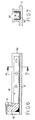
- eine Seitenansicht des einen Schenkels eines U-förmigen Zugankers in größerem Maßstab,
- FIG. 4
- eine Querschnittansicht durch die Lagerung des Zugankers im Gehäuse,
- FIG. 5
- eine Querschnittansicht durch eine alternative Lagerung des Zugankers im Gehäuse,
- FIG. 6
- einen Längsschnitt durch einen im Gehäuse elastisch eingegossenen Zuganker,
- FIG. 7
- eine Querschnittansicht längs der Linie 7-7 der FIG. 6,
- Ein Schraubstock 10 mit Gehäuse 12, gehäusefester Spannbacke 14, in der Spannbacke 14 schwimmend aufgehängtem U-förmigem Zuganker 16, der einen ersten Schenkel 18, ein sich längs des Schraubstockes erstreckendes Joch 20 sowie einen zweiten Schenkel 22 aufweist, der eine Gewindemutter für eine Schraubspindel 24 bildet, deren eines Ende eine bewegliche Spannbacke 26 hintergreift, welche am Gehäuse 12 in Längsschienen verschiebbar geführt ist, ist dadurch gekennzeichnet, daß der Zuganker 16 mittels einer Dreipunktaufhängung im Gehäuse 12 schwimmend gelagert ist. Der Zuganker 16 mit den beiden Schenkeln 18,22 und dem Joch 20 könnte ein einstückiges Bauteil bilden. Im Ausführungsbeispiel ist der andere Schenkel 22 am Joch 20 des Zugankers 16 mittels Steckbolzen 28 stufenweise verstellbar angeordnet.
- Der Zugankerschenkel 18 weist an seinen beiden Seitenflächen jeweils eine muldenartige Vertiefung 30 auf. Die beiden Vertiefungen 30 sind quer ausgerichtet. Die Seitenwände der festen Spannbacke 14 haben koaxiale Querbohrungen 32, in denen sich je ein Rastbolzen 34, eine Druckfeder 36 und ein Gewindestück 38 befinden. Die Gewindestücke 38 sind soweit in den Querbohrungen 32 verschraubt, daß die Rastbolzen 34 mit einer gewissen Vorspannung in die muldenartigen Vertiefungen 30 des Zugankerschenkels 18 eindringen. Die Rastbolzen 34 und die Vertiefungen 30 sind bezüglich einander so ausgebildet, daß eine relative Verschiebung in sämtlichen Richtungen parallel zu den Seitenflächen des Schenkels 18 möglich ist. Die muldenartigen Vertiefungen 30 sind z.B. konisch ausgebildet, während die Vorderflächen der Rastbolzen 34 halbkugelartig geformt sind. Die Federn 36 suchen den Zuganker 16 so einzustellen, daß die die Zentren der muldenartigen Vertiefungen 30 enthaltende Querachse mit der Querachse der Bohrungen 32 zusammenfällt.
- Das der Spannzone zugewandte obere Ende des linken Schenkels 18 ist in Form einer im Querschnitt abgerundeten Nase 40 ausgebildet. An die Nase 40 schließt sich eine schräge ebene Vorderfläche 42 des Schenkels 18 an, die mit einer zur Spannfläche parallelen Ebene 44 einen Winkel von etwa 5° einschließt. Die Hinterfläche der festen Spannbacke 14 liegt im Spannzustand in der mit 44 bezeichneten Ebene, sodaß sich unterhalb der Nase 40 ein Spalt 48 bildet, der zum Joch 20 des Zugankers 16 allmählich breiter wird.
- Der Schenkel 18 des Zugankers 16 besteht aus Vollmaterial. Das Joch 20 hat dagegen einen U-förmigen Querschnitt, in den der andere Schenkel 22 eingreift. Die Querschnittskontur des Schenkels 18 ist über die gesamte Zugankerbreite dieselbe.
- Die muldenartigen Vertiefungen 30 im Schenkel 18 und die Bohrungen 32 in der festen Spannbacke 14 sind so angeordnet, daß bei gegenseitiger Querausrichtung die Nase 40 die Hinterfläche 46 der festen Spannbacke etwa berührt. Bei der Herstellung brauchen jedoch keine großen Genauigkeitsanforderungen eingehalten zu werden. Wird nämlich der Schraubstock 10 gespannt, so richtet sich der Zuganker 16 selbsttätig aus und zwar derart, daß die Rastbolzen 34 sich in den muldenartigen Vertiefungen 30 derart verlagern, daß ein durchgehender Kontakt der Nase 40 an der Hinterfläche 46 der festen Spannbacke 14 theoretisch längs einer Berührungslinie stattfindet. Beim weiteren Spannen verformt sich der Zuganker und die Nase 40 wälzt sich an der Hinterfläche 46 ab, wobei aber gleichwohl noch Linienberührung erhalten bleibt.
- Zur Positionierung des Zugankers reicht ansich die beidseitige Halterung des Schenkels 18 aus. Zusätzlich ist in FIG. 1 im Bereich des freien Endes des Joches 20 ein in den Boden des Gehäuses 12 eingesetzter federnder Rastbolzen entsprechend den Elementen 34, 36, 38 vorgesehen, sodaß eine Dreipunktaufhängung erzielt wird. Beim Durchbiegen des Joches 20 überträgt somit das Jochende keine Kräfte auf den Gehäuseboden.
- FIG. 5 veranschaulicht eine Alternative zur schwimmenden Lagerung des Zugankerschenkels 18. Die Seitenwände der festen Spannbacke 14 weisen quer ausgerichtete Bohrungen 50 auf, in die elastisch verformbare Hülsen 52 eingesetzt sind. Der Schenkel 18 hat eine koaxiale Bohrung mit einem Innendurchmesser gleich demjenigen der elastischen Hülsen 52. Ein Steckbolzen 54 durchsetzt die Bohrung des Schenkels 18 und die elastischen Hülsen 52.
- Alternativ ist es auch möglich, in dem Schenkel 18 eine elastische Hülse 52 einzusetzen, jedoch wird die erstbeschriebene Ausführung gemäß FIG. 5 vorgezogen, um den Schenkel 18 möglichst wenig zu schwächen.
- Die FIGUREN 6 und 7 veranschaulichen eine dritte Alternative zur schwimmenden Lagerung des Zugankers 16. Der Zuganker 16 ist bodenseitig und an beiden Seitenflächen über seine gesamte Länge mittels elastischer Schichten 56, 58 mit dem Gehäuse 12 verbunden. D.h. die zwischen Zuganker 16 und Gehäuse gebildeten Spalten sind mit elastischem Material ausgegossen. Das elastische Material gewährleistet eine Selbsteinstellung des Zugankers 16 während des Spannvorganges und verhindert gleichzeitig, daß Metallspäne in die Spalten eindringen können. Eine zusätzliche mechanische Lagerung des Zugankers 16 am Gehäuse 12 entfällt damit.
Claims (8)
- Spanngerät, insbesondere Präzisions-Hochdruckspanner, mit einem Gehäuse (12), einer gehäusefesten Spannbacke (14), einem im Gehäuse (12) angeordneten separaten, etwa U-förmigen Zuganker (16), dessen einer Schenkel (18) die feste Spannbacke (14) hintergreift und dessen anderer Schenkel (22) eine, von einer Schraubspindel (24) durchsetzte Gewindemutter bildet, wobei das eine Ende der Schraubspindel eine verschiebbare Spannbacke (26) hintergreift und die Spannflächen beider Spannbacken (14, 26) parallel liegen und wobei zwischen dem einen Schenkel (18) und der festen Spannbacke (14) ein sich über mindestens den größten Teil der Schenkelbreite erstreckender angenähert linienförmiger Kontakt besteht und ein davon getrenntes Haltemittel (30, 34; 50,52;56,58) vorgesehen ist, das den Zuganker (16) sich selbsteinstellend im Gehäuse (12) in Spannrichtung verschiebbar und um eine, die Kontaktlinie und die Gehäusebodenfläche rechtwinklig kreuzende imaginäre Achse begrenzt schwenkbar lagert, dadurch gekennzeichnet, daß das Haltemittel (30, 34; 50,52; 56, 58) für eine allseitige Beweglichkeit des Zugankers (16) elastisch ausgebildet ist.
- Spanngerät nach Anspruch 1, dadurch gekennzeichnet, daß der eine Schenkel (18) im Bereich der Kontaktlinie eine im Querschnitt konvex gerundete Nase (40) aufweist, daß angrenzend an die Nase zwischen dem einen Schenkel (18) und der festen Spannbacke (14) ein bis zum Joch (20) des Zugankers (16) reichender Freiraumspalt (48) gebildet ist und daß sich die Breite des Freiraumspaltes (48) zum Zugankerjoch (20) hin allmählich vergrößert.
- Spanngerät nach Anspruch 2, dadurch gekennzeichnet, daß die an die Nase (40) angrenzende Vorderfläche (42) des einen Schenkels (18) mit der die Kontaktlinie enthaltenden, parallel zur Spannfläche angeordneten Hinterfläche (46) der festen Spannbacke (14) einen spitzen Winkel bildet.
- Spanngerät nach einem der Ansprüche 1 bis 3, dadurch gekennzeichnet, daß in beiden Seitenflächen des einen Schenkels (18) je eine etwa muldenartige Ausnehmung (30) vorgesehen ist, in die ein in jeder Seitenwand der festen Spannbacke (14) federnd gelagerter Bolzen (34) in der Seitenflächenebene relativ verschiebbar eingreift.
- Spanngerät nach einem der Ansprüche 1 bis 3, dadurch gekennzeichnet, daß mit dem einen Schenkel (18) beidseitig vorspringende koaxiale Bolzenenden (54) in Verbindung stehen, die mittels der im Schenkel (18) und/oder in der festen Spannbacke (14) vorgesehenen Haltemittel (52) elastisch gelagert sind.
- Spanngerät nach Anspruch 5, dadurch gekennzeichnet, daß die Haltemittel aus elastisch verformbaren Hülsen (52) bestehen.
- Spanngerät nach einem der Ansprüche 1 bis 3, dadurch gekennzeichnet, daß zwischen Zuganker (16) und Gehäuse (12) elastisch verformbare Verbindungsmittel (56, 58) vorgesehen sind.
- Spanngerät nach Anspruch 7, dadurch gekennzeichnet, daß die zwischen Zuganker (16) und Gehäuse (12) gebildeten Spalten durch eine elastische Masse (56, 58) ausgegossen sind.
Priority Applications (1)
| Application Number | Priority Date | Filing Date | Title |
|---|---|---|---|
| AT86111577T ATE69190T1 (de) | 1985-09-12 | 1986-08-21 | Spanngeraet. |
Applications Claiming Priority (2)
| Application Number | Priority Date | Filing Date | Title |
|---|---|---|---|
| DE19853532490 DE3532490A1 (de) | 1985-09-12 | 1985-09-12 | Spanngeraet |
| DE3532490 | 1985-09-12 |
Publications (3)
| Publication Number | Publication Date |
|---|---|
| EP0215326A2 EP0215326A2 (de) | 1987-03-25 |
| EP0215326A3 EP0215326A3 (en) | 1988-10-05 |
| EP0215326B1 true EP0215326B1 (de) | 1991-11-06 |
Family
ID=6280733
Family Applications (1)
| Application Number | Title | Priority Date | Filing Date |
|---|---|---|---|
| EP86111577A Expired - Lifetime EP0215326B1 (de) | 1985-09-12 | 1986-08-21 | Spanngerät |
Country Status (5)
| Country | Link |
|---|---|
| US (1) | US4664365A (de) |
| EP (1) | EP0215326B1 (de) |
| AT (1) | ATE69190T1 (de) |
| DE (2) | DE3532490A1 (de) |
| ES (1) | ES2002333A6 (de) |
Families Citing this family (10)
| Publication number | Priority date | Publication date | Assignee | Title |
|---|---|---|---|---|
| US4759535A (en) * | 1986-05-31 | 1988-07-26 | Tamotsu Takasugi | Machine vice |
| US5921534A (en) * | 1997-07-03 | 1999-07-13 | Chick Workholding Solutions, Inc. | Detachable jaw for vise-like workholding apparatus |
| US7651078B2 (en) * | 2003-12-12 | 2010-01-26 | Irwin Industrial Tool Company | Clamping and/or spreading tool |
| US7604224B2 (en) * | 2005-09-28 | 2009-10-20 | The Stanley Works | Motorized clamp |
| US7131642B1 (en) | 2005-09-28 | 2006-11-07 | Stanley Tools And Hardware | Adjustable clamp |
| US7090209B1 (en) | 2005-09-28 | 2006-08-15 | Stanley Tools And Hardware | Adjustable clamp and method of using an adjustable clamp |
| US7389978B2 (en) * | 2005-09-28 | 2008-06-24 | The Stanley Works | Adjustable clamp |
| US8870044B1 (en) * | 2009-03-31 | 2014-10-28 | Brica, Inc. | Snack and drink holder |
| KR200477867Y1 (ko) * | 2013-03-20 | 2015-07-30 | 윤환식 | 공작물 고정용 바이스 |
| CN105041793A (zh) * | 2015-06-09 | 2015-11-11 | 郭斌 | 一种石膏烘干机烘箱板角紧固器 |
Family Cites Families (12)
| Publication number | Priority date | Publication date | Assignee | Title |
|---|---|---|---|---|
| US2889729A (en) * | 1955-12-28 | 1959-06-09 | Orner Harry | Apparatus for screw tensioning to elongation values |
| US2882656A (en) * | 1957-07-19 | 1959-04-21 | Manchester Machine & Tool Co | Squaring fixture |
| US3312461A (en) * | 1964-10-16 | 1967-04-04 | Glenn A Copron | Vise |
| GB1185702A (en) * | 1967-01-31 | 1970-03-25 | Carolyn Rosemary Soar | Improvements in or relating to Engineering Vices |
| GB1181398A (en) * | 1967-11-01 | 1970-02-18 | Kenneth Reginald Beetlestone | A New or Improved Vice |
| JPS6023950B2 (ja) * | 1978-11-01 | 1985-06-10 | 保 高杉 | マシンバイス |
| FR2449511A1 (fr) * | 1979-02-20 | 1980-09-19 | Boucher Freres Sarl Ets | Support de piece pour usinage par machine-outil |
| JPS5946745B2 (ja) * | 1979-06-28 | 1984-11-14 | 保 高杉 | マシンバイス |
| US4328709A (en) * | 1980-04-18 | 1982-05-11 | Schramm Wayne E | Electronic audio visual torque indicator adapter |
| FR2559085B2 (fr) * | 1984-02-02 | 1987-06-26 | Boucher Freres Sarl Ets | Dispositif permettant de maintenir une piece a usiner dans une position determinee par rapport a une machine-outil sur laquelle ce dispositif peut etre fixe |
| US4569509A (en) * | 1984-04-02 | 1986-02-11 | Johann Good | Vise, particularly a machine vise |
| EP0162992B1 (de) * | 1984-05-26 | 1987-05-20 | Eduard Wille GmbH & Co. | Einarmiger Drehmomentschlüssel |
-
1985
- 1985-09-12 DE DE19853532490 patent/DE3532490A1/de not_active Withdrawn
-
1986
- 1986-08-21 EP EP86111577A patent/EP0215326B1/de not_active Expired - Lifetime
- 1986-08-21 AT AT86111577T patent/ATE69190T1/de active
- 1986-08-21 DE DE8686111577T patent/DE3682354D1/de not_active Expired - Fee Related
- 1986-08-28 US US06/901,411 patent/US4664365A/en not_active Expired - Lifetime
- 1986-09-12 ES ES8601859A patent/ES2002333A6/es not_active Expired
Also Published As
| Publication number | Publication date |
|---|---|
| ES2002333A6 (es) | 1988-08-01 |
| EP0215326A3 (en) | 1988-10-05 |
| US4664365A (en) | 1987-05-12 |
| EP0215326A2 (de) | 1987-03-25 |
| DE3532490A1 (de) | 1987-03-19 |
| ATE69190T1 (de) | 1991-11-15 |
| DE3682354D1 (de) | 1991-12-12 |
Similar Documents
| Publication | Publication Date | Title |
|---|---|---|
| DE19857913C2 (de) | Kupplungsvorrichtung | |
| DE3105234C2 (de) | Klemmen zum Auspannen von Werkstücken | |
| AT520440B1 (de) | Niederhalter | |
| EP1955816A2 (de) | Spannvorrichtung | |
| EP0215326B1 (de) | Spanngerät | |
| DE4138285A1 (de) | Hydraulische abkantpresse | |
| DE69313708T2 (de) | Führungseinheit für geradlinige Wälzbewegung | |
| DE19858159C2 (de) | Kupplungsvorrichtung | |
| EP0052310A1 (de) | Gleiskettenspanneinrichtung, insbesondere bei einem Raupenschlepper | |
| EP2105257A2 (de) | Aufsatzspannbacken | |
| EP0362753B1 (de) | Einspannvorrichtung | |
| EP1348514A2 (de) | Schlittensystem | |
| DE69702418T2 (de) | Klemm- und Eckverbindungsvorrichtung zwischen zwei rechtwinklig zueinander stehende Metallhohlprofilen | |
| DE60211080T2 (de) | Verstellbare Formmatrize, insbesondere für Abkantpressen | |
| DE69915813T2 (de) | Flachbackenwalzmaschine mit Vorrichtung zum miteinander Verbinden der Backentragrahmen und Befestigungsverfahren hierfür | |
| EP2394790B1 (de) | Aufsatzbacke für einen Schraubstock | |
| DE2837895A1 (de) | Kupplung fuer optische fasern | |
| DE3837444C1 (en) | Device for mutual clamping of two objects | |
| DE2645290B1 (de) | Vorrichtung zur Linearfuehrung,insbesondere Geradfuehrung | |
| DE19521831A1 (de) | Spannvorrichtung zum Einspannen von Werkstücken | |
| EP2626173B1 (de) | Spannpratze für eine Spannvorrichtung | |
| DE1045845B (de) | Tuerdruecker | |
| DE69013138T2 (de) | Klemmvorrichtung für ein Messer einer Fleischenthäutungsmaschine. | |
| DE69804713T2 (de) | Zusammenbau von zwei miteinander langgestreckten Elementen | |
| DE3042418A1 (de) | Werkzeug zum bearbeiten der anschlussdraehte von elektrischen bauelementen |
Legal Events
| Date | Code | Title | Description |
|---|---|---|---|
| PUAI | Public reference made under article 153(3) epc to a published international application that has entered the european phase |
Free format text: ORIGINAL CODE: 0009012 |
|
| AK | Designated contracting states |
Kind code of ref document: A2 Designated state(s): AT BE CH DE FR GB IT LI LU NL SE |
|
| PUAL | Search report despatched |
Free format text: ORIGINAL CODE: 0009013 |
|
| AK | Designated contracting states |
Kind code of ref document: A3 Designated state(s): AT BE CH DE FR GB IT LI LU NL SE |
|
| 17P | Request for examination filed |
Effective date: 19881019 |
|
| 17Q | First examination report despatched |
Effective date: 19891213 |
|
| GRAA | (expected) grant |
Free format text: ORIGINAL CODE: 0009210 |
|
| AK | Designated contracting states |
Kind code of ref document: B1 Designated state(s): AT BE CH DE FR GB IT LI LU NL SE |
|
| REF | Corresponds to: |
Ref document number: 69190 Country of ref document: AT Date of ref document: 19911115 Kind code of ref document: T |
|
| REF | Corresponds to: |
Ref document number: 3682354 Country of ref document: DE Date of ref document: 19911212 |
|
| GBT | Gb: translation of ep patent filed (gb section 77(6)(a)/1977) | ||
| ET | Fr: translation filed | ||
| ITF | It: translation for a ep patent filed | ||
| PLBE | No opposition filed within time limit |
Free format text: ORIGINAL CODE: 0009261 |
|
| STAA | Information on the status of an ep patent application or granted ep patent |
Free format text: STATUS: NO OPPOSITION FILED WITHIN TIME LIMIT |
|
| 26N | No opposition filed | ||
| EPTA | Lu: last paid annual fee | ||
| EAL | Se: european patent in force in sweden |
Ref document number: 86111577.2 |
|
| PGFP | Annual fee paid to national office [announced via postgrant information from national office to epo] |
Ref country code: BE Payment date: 19990802 Year of fee payment: 14 |
|
| PGFP | Annual fee paid to national office [announced via postgrant information from national office to epo] |
Ref country code: SE Payment date: 19990803 Year of fee payment: 14 |
|
| PGFP | Annual fee paid to national office [announced via postgrant information from national office to epo] |
Ref country code: CH Payment date: 19990806 Year of fee payment: 14 |
|
| PGFP | Annual fee paid to national office [announced via postgrant information from national office to epo] |
Ref country code: AT Payment date: 19990816 Year of fee payment: 14 |
|
| PGFP | Annual fee paid to national office [announced via postgrant information from national office to epo] |
Ref country code: GB Payment date: 19990818 Year of fee payment: 14 |
|
| PGFP | Annual fee paid to national office [announced via postgrant information from national office to epo] |
Ref country code: LU Payment date: 19990826 Year of fee payment: 14 |
|
| PGFP | Annual fee paid to national office [announced via postgrant information from national office to epo] |
Ref country code: NL Payment date: 19990831 Year of fee payment: 14 Ref country code: FR Payment date: 19990831 Year of fee payment: 14 |
|
| PGFP | Annual fee paid to national office [announced via postgrant information from national office to epo] |
Ref country code: DE Payment date: 19991025 Year of fee payment: 14 |
|
| PG25 | Lapsed in a contracting state [announced via postgrant information from national office to epo] |
Ref country code: LU Free format text: LAPSE BECAUSE OF NON-PAYMENT OF DUE FEES Effective date: 20000821 Ref country code: GB Free format text: LAPSE BECAUSE OF NON-PAYMENT OF DUE FEES Effective date: 20000821 Ref country code: AT Free format text: LAPSE BECAUSE OF NON-PAYMENT OF DUE FEES Effective date: 20000821 |
|
| PG25 | Lapsed in a contracting state [announced via postgrant information from national office to epo] |
Ref country code: SE Free format text: LAPSE BECAUSE OF NON-PAYMENT OF DUE FEES Effective date: 20000822 |
|
| PG25 | Lapsed in a contracting state [announced via postgrant information from national office to epo] |
Ref country code: LI Free format text: LAPSE BECAUSE OF NON-PAYMENT OF DUE FEES Effective date: 20000831 Ref country code: CH Free format text: LAPSE BECAUSE OF NON-PAYMENT OF DUE FEES Effective date: 20000831 Ref country code: BE Free format text: LAPSE BECAUSE OF NON-PAYMENT OF DUE FEES Effective date: 20000831 |
|
| BERE | Be: lapsed |
Owner name: GEORG KESEL G.M.B.H. & CO. K.G. Effective date: 20000831 |
|
| PG25 | Lapsed in a contracting state [announced via postgrant information from national office to epo] |
Ref country code: NL Free format text: LAPSE BECAUSE OF NON-PAYMENT OF DUE FEES Effective date: 20010301 |
|
| GBPC | Gb: european patent ceased through non-payment of renewal fee |
Effective date: 20000821 |
|
| REG | Reference to a national code |
Ref country code: CH Ref legal event code: PL |
|
| EUG | Se: european patent has lapsed |
Ref document number: 86111577.2 |
|
| PG25 | Lapsed in a contracting state [announced via postgrant information from national office to epo] |
Ref country code: FR Free format text: LAPSE BECAUSE OF NON-PAYMENT OF DUE FEES Effective date: 20010430 |
|
| NLV4 | Nl: lapsed or anulled due to non-payment of the annual fee |
Effective date: 20010301 |
|
| PG25 | Lapsed in a contracting state [announced via postgrant information from national office to epo] |
Ref country code: DE Free format text: LAPSE BECAUSE OF NON-PAYMENT OF DUE FEES Effective date: 20010501 |
|
| REG | Reference to a national code |
Ref country code: FR Ref legal event code: ST |
|
| PG25 | Lapsed in a contracting state [announced via postgrant information from national office to epo] |
Ref country code: IT Free format text: LAPSE BECAUSE OF NON-PAYMENT OF DUE FEES;WARNING: LAPSES OF ITALIAN PATENTS WITH EFFECTIVE DATE BEFORE 2007 MAY HAVE OCCURRED AT ANY TIME BEFORE 2007. THE CORRECT EFFECTIVE DATE MAY BE DIFFERENT FROM THE ONE RECORDED. Effective date: 20050821 |