EP0215217B1 - Freight container - Google Patents
Freight container Download PDFInfo
- Publication number
- EP0215217B1 EP0215217B1 EP19860109115 EP86109115A EP0215217B1 EP 0215217 B1 EP0215217 B1 EP 0215217B1 EP 19860109115 EP19860109115 EP 19860109115 EP 86109115 A EP86109115 A EP 86109115A EP 0215217 B1 EP0215217 B1 EP 0215217B1
- Authority
- EP
- European Patent Office
- Prior art keywords
- corner
- freight container
- fitting
- section
- container
- Prior art date
- Legal status (The legal status is an assumption and is not a legal conclusion. Google has not performed a legal analysis and makes no representation as to the accuracy of the status listed.)
- Expired
Links
Images

Classifications
-
- B—PERFORMING OPERATIONS; TRANSPORTING
- B65—CONVEYING; PACKING; STORING; HANDLING THIN OR FILAMENTARY MATERIAL
- B65D—CONTAINERS FOR STORAGE OR TRANSPORT OF ARTICLES OR MATERIALS, e.g. BAGS, BARRELS, BOTTLES, BOXES, CANS, CARTONS, CRATES, DRUMS, JARS, TANKS, HOPPERS, FORWARDING CONTAINERS; ACCESSORIES, CLOSURES, OR FITTINGS THEREFOR; PACKAGING ELEMENTS; PACKAGES
- B65D90/00—Component parts, details or accessories for large containers
- B65D90/0026—Corner fittings characterised by shape, configuration or number of openings
-
- B—PERFORMING OPERATIONS; TRANSPORTING
- B65—CONVEYING; PACKING; STORING; HANDLING THIN OR FILAMENTARY MATERIAL
- B65D—CONTAINERS FOR STORAGE OR TRANSPORT OF ARTICLES OR MATERIALS, e.g. BAGS, BARRELS, BOTTLES, BOXES, CANS, CARTONS, CRATES, DRUMS, JARS, TANKS, HOPPERS, FORWARDING CONTAINERS; ACCESSORIES, CLOSURES, OR FITTINGS THEREFOR; PACKAGING ELEMENTS; PACKAGES
- B65D7/00—Containers having bodies formed by interconnecting or uniting two or more rigid, or substantially rigid, components made wholly or mainly of metal
- B65D7/12—Containers having bodies formed by interconnecting or uniting two or more rigid, or substantially rigid, components made wholly or mainly of metal characterised by wall construction or by connections between walls
- B65D7/14—Containers having bodies formed by interconnecting or uniting two or more rigid, or substantially rigid, components made wholly or mainly of metal characterised by wall construction or by connections between walls of skeleton or like apertured construction, e.g. baskets or carriers formed of wire mesh, of interconnected bands, bars, or rods, or of perforated sheet metal
-
- B—PERFORMING OPERATIONS; TRANSPORTING
- B65—CONVEYING; PACKING; STORING; HANDLING THIN OR FILAMENTARY MATERIAL
- B65D—CONTAINERS FOR STORAGE OR TRANSPORT OF ARTICLES OR MATERIALS, e.g. BAGS, BARRELS, BOTTLES, BOXES, CANS, CARTONS, CRATES, DRUMS, JARS, TANKS, HOPPERS, FORWARDING CONTAINERS; ACCESSORIES, CLOSURES, OR FITTINGS THEREFOR; PACKAGING ELEMENTS; PACKAGES
- B65D90/00—Component parts, details or accessories for large containers
- B65D90/0006—Coupling devices between containers, e.g. ISO-containers
- B65D90/0013—Twist lock
-
- G—PHYSICS
- G05—CONTROLLING; REGULATING
- G05B—CONTROL OR REGULATING SYSTEMS IN GENERAL; FUNCTIONAL ELEMENTS OF SUCH SYSTEMS; MONITORING OR TESTING ARRANGEMENTS FOR SUCH SYSTEMS OR ELEMENTS
- G05B2219/00—Program-control systems
- G05B2219/30—Nc systems
- G05B2219/37—Measurements
- G05B2219/37092—Display position actual and or target
-
- G—PHYSICS
- G05—CONTROLLING; REGULATING
- G05B—CONTROL OR REGULATING SYSTEMS IN GENERAL; FUNCTIONAL ELEMENTS OF SUCH SYSTEMS; MONITORING OR TESTING ARRANGEMENTS FOR SUCH SYSTEMS OR ELEMENTS
- G05B2219/00—Program-control systems
- G05B2219/30—Nc systems
- G05B2219/41—Servomotor, servo controller till figures
- G05B2219/41036—Position error in memory, lookup table for correction actual position
Definitions
- the invention relates to a freight container according to the preamble of claim 1.
- a corner fitting for such a freight container is described in European patent application publication number 54881.
- European patent application publication number 54881 it explains how a corner fitting can be produced from a circular or square blank with a central circular or square opening by folding processes, in which two quadrants of the blank overlap to form a surface of the corner fitting.
- the opening in the corner area facing away from the container is only formed by a cut, so that an outwardly projecting, beak-like projection results at this corner, and below this projection there is a hole in the same edge through which a crane hook inserted behind the projection can emerge with its tip.
- holes are provided in the walls of the corner fitting according to the earlier patent application, which, like in the conventional corner fitting according to ISO standard 1161, serve to introduce special devices for the lateral coupling of adjacent containers.
- German laid-open specification 2942104 shows freight containers which, apart from the corner opening, also correspond to the preamble of claim 1.
- the invention has for its object to provide a freight container that allows handling with forklifts without additional structural elements.
- the profile elements forming the container frame themselves are used as stacker channels, the corner fittings, on which three profile elements converge in each case, being designed in such a way that the stacker channels which are open at the end are accessible through the corner fittings. If all the profile elements are designed as forklift channels, such a container can be picked up in all positions, namely lying, standing and upright, from each of its four sides by the arms of a forklift.
- the profile elements have a hollow profile and are preferably essentially square or circular in cross section. This design has the advantage of higher bending stiffness compared to the flat cross sections of conventional stacker channels. Alternatively, it is also possible to use profile elements with an L-cross section, in which case only the top two profile elements of a container can be used as forklift channels.
- the corner fittings offer as much space as possible for welding the profile elements with a maximum usable corner opening.
- the rounded corners of the corner opening promote the snug fitting and locking of inserted crane hooks when pulling diagonally.
- the development of the invention according to claim 5 also has the advantage that the corner fittings for connecting to the edge elements offer relatively large areas.
- the development of the invention according to claim 6 is advantageous in that the openings of the corner fittings suitable for carrying through crane hook tips or coupling elements lie in the particularly dimensionally stable edge regions. Due to the double material thickness achieved according to claim 7, a particular strength of these claimed openings is achieved.
- the edge openings formed by the cutouts mentioned in claims 6 and 7 can furthermore advantageously be used for the passage of pins or hooks which can be inserted into the ends of forklift arms or can be firmly connected to them, whereby a secure mounting on the forklift arms is then also achieved will, if these are only inserted a short distance into the corner fittings and profile elements in the manner of the upper hooks of container side spreaders.
- FIG. 1 and 2 show the structural elements forming a lower left corner region of a freight container, for which a corner fitting 30, three elements of a container frame forming perpendicular profile elements 31, 32, 33 and a node piece 34 reinforcing the corner fitting (only in FIG. 2 shown) belong.
- the corner fitting is as above refines, from three mutually perpendicular wall elements 21, 22, 23, which together form a corner opening 24.
- the corner fitting 30 can be produced from a flat blank by means of edges and welding or also by pressing, pulling or some other deformation process.
- the knot piece 34 is the piece of material that arises when the corner opening 24 is cut out of the corner fitting 30. At the three edges, the corner fitting 30 also has an edge hole 25 cut out in both abutting wall elements.
- the three profile elements 31, 32, 33 are pushed into the edge regions of the corner fitting 30 to such an extent that they end shortly before the corner opening 24. For their part, they each also have an edge hole 26 which is essentially flush with the corresponding edge hole 25 of the corner fitting 30. In this position, the profile elements 31, 32, 33 are welded to the corner fitting 30 at the points indicated in FIG. 2.
- the node piece 34 is inserted in such a way that its two vertical side surfaces partially abut the vertical inner surfaces of the profile elements 31 and 33 and are also welded there.
- the connection between the node piece 34 and the vertical profile element 32 can, if necessary, take place via an additional component (not shown in the drawings). If the mutually adjacent perpendicular edges of the node piece 34 and the vertical profile element 32 are not rounded off too much, the two parts can also be welded directly to these edges.
- the profile elements 31, 32, 33 are designed as hollow profile elements with an essentially square cross section.
- the corner opening 24 of the corner fitting 30 is formed by three substantially square cutouts lying in the individual wall elements 21, 22, 23, the corner of which is averted from the common corner. These square areas are somewhat larger than the clear cross section of the profile elements 31, 32, 33, so that the profile elements can be used as stacker channels and are accessible with their full cross section through the corner opening 24.
- the outer shape of the three wall elements 21, 22 and 23 forming the corner fitting 30 corresponds in each case to a quadrant of a circle, the centers of the circles coinciding in the (imaginary) corner of the corner fitting 30.
- a container If a container is set up at all of its eight corners as shown in Figures 1 and 2, it can be lifted in any position and from any side by means of a forklift, since the forklift arms go through each corner fitting in each of the three directions can be introduced by the relevant profile element 31, 32, 33 formed truck channel. Because of the forklift channel cross-sections, which are square for reasons of symmetry, it is advantageous if the fork arms or fork tines also have a square cross-section. This is an advantage over the usual flat tine cross sections because of the increased bending stiffness.
- the fork arms can be inserted into the two lower or the two upper corner fittings and the profile elements behind them over a correspondingly large length.
- two significantly shorter fork arms or mandrels into the two upper corner fittings and profile elements over a relatively short length and to secure them with locking pins which are inserted through corresponding edge holes 25, 26 into corresponding recesses in the stacker arms or into appropriate distance from the stacker end of the arms are firmly connected to them.
- profile elements 31, 32, 33 which are arranged in the usual way so that their edges form the outer edges of the container frame.
- only the top two profile elements corresponding to the respective position of the container can be used as stacker channels.
- coupling elements When coupling adjacent or stacked containers, coupling elements can be through the corner openings 24 or through the Insert the edge opening 25, 26 of the immediately adjacent corner fittings 30 of the two containers, whereby these coupling elements can additionally be fixed through the other holes or openings.
- the embodiment according to FIG. 3 differs from that according to FIGS. 1 and 2 in that the corner opening 24 'is formed by three quarter-circle arcs, the radius of which is substantially equal to the diagonal of the clear cross section of the profile elements 31, 32, 33.
- the wall elements, of which in particular the wall element 23 can be seen in FIG. 3, are reduced to a relatively narrow ring which extends only up to part of the edge holes 26 provided in the profile elements 31, 32. In these edge areas, the corner fitting according to FIG. 3 is provided with edge cutouts 25 '.
- edge holes 25, 26 in the two abutting wall elements are each semicircular (the edge hole 25 provided in the corner fitting for accommodating tolerances in the mutual alignment is somewhat larger than the edge hole 26 in the profile elements ), it is also possible to form the edge hole 26 'in the profile elements by means of a rectangular or oblique cutout, as is indicated in FIG. 3 by dashed lines. A straight cut running over the edge of the profile element is particularly favorable in terms of production technology.
- the wall elements of the corner fitting 30 "are reduced to an even smaller material width.
- the corner fitting ends outside the edge holes 26" provided in the profile elements 31, 32.
- a knot piece 34 is again provided, which in this case is used in such a way that its vertical surface facing the viewer lies against and is welded to the wall element 23 ′′, while the other two surfaces of the knot piece 34 are connected to the upper one
- the surface of the profile element 31 or the right inner surface of the profile element 32 are welded in this case, a connection between the node piece 34 and the third profile element 33 can again be achieved via an additional component (not shown).
- FIG. 5 Another knot piece 35 is shown in FIG. 5, which essentially consists of an equilateral flat surface piece with trapezoidal sections bent on the three sides.
- the equilateral triangular surface extends essentially perpendicular to the space diagonal of the container corner defined by the three profile elements 31, 32, 33.
- the trapezoidal sections are edged towards the corner with respect to the equilateral surfaces, so that their side edges bear against the inner surfaces of the profile elements 31, 32, 33 and are welded to them. With the node piece 35, a uniform and secure stiffening is achieved compared to all three profile elements.
- a knot piece can also be used in the embodiment according to FIG. 3.
- the node piece can be designed according to Figures 2 and 4 or according to Figure 5.
- the corner fitting can be constructed from triangular or square wall elements instead of the circular quadrants shown.
- the corner opening 24 of the corner fitting can in any case be formed from square cutouts with a rounded corner according to FIG. 1 or 2 or from quarter-circle-shaped cutouts according to FIGS. 3 and 4 or from triangular cutouts.
Description
Die Erfindung betrifft einen Frachtcontainer nach dem Oberbegriff des Patentanspruchs 1.The invention relates to a freight container according to the preamble of claim 1.
Ein Eckbeschlag für einen derartigen Frachtcontainer ist in der europäischen Patentanmeldung Veröffentlichungsnummer 54881 beschrieben. Unter anderem ist dort erläutert, wie aus einem kreisförmigen oder quadratischen Zuschnitt mit einer mittleren kreisförmigen oder quadratischen Öffnung durch Kantungsvorgänge ein Eckbeschlag herstellbar ist, bei dem zwei Quadranten desZuschnitts unter Bildung einer Fläche des Eckbeschlags einander überlappen. Bei einer Ausführungsform wird dort die Öffnung in dem dem Container abgewandten Eckbereich lediglich durch einen Schnitt gebildet, so dass sich an dieser Ecke ein nach aussen ragender, gekanteter schnabelartiger Vorsprung ergibt, und unterhalb dieses Vorsprungs ist in der gleichen Kante ein Loch vorgesehen, durch das ein hinter dem Vorsprung eingeführter Kranhaken mit seiner Spitze austreten kann. Im übrigen sind in den Wänden des Eckbeschlages nach der früheren Patentanmeldung Löcher vorgesehen, die wie bei dem herkömmlichen Eckbeschlag nach der ISO-Norm 1161 zum Einführen spezieller Vorrichtungen für die seitliche Kopplung benachbarter Container dienen.A corner fitting for such a freight container is described in European patent application publication number 54881. Among other things, it explains how a corner fitting can be produced from a circular or square blank with a central circular or square opening by folding processes, in which two quadrants of the blank overlap to form a surface of the corner fitting. In one embodiment, the opening in the corner area facing away from the container is only formed by a cut, so that an outwardly projecting, beak-like projection results at this corner, and below this projection there is a hole in the same edge through which a crane hook inserted behind the projection can emerge with its tip. For the rest, holes are provided in the walls of the corner fitting according to the earlier patent application, which, like in the conventional corner fitting according to ISO standard 1161, serve to introduce special devices for the lateral coupling of adjacent containers.
Die deutsche Offenlegungsschrift 2942104 zeigt Frachtcontainer, die, von der Ecköffnung abgesehen, ebenfalls dem Oberbegriff des Patentanspruchs 1 entsprechen.German laid-open specification 2942104 shows freight containers which, apart from the corner opening, also correspond to the preamble of claim 1.
Um die Handhabung von Containern mittels Gabelstaplern zu ermöglichen, ist es üblich, an der Unterseite der Container zwischen den Eckbeschlägen Kanäle zum Einführen der Staplerarme vorzusehen. Derartige Kanäle verringern einerseits das Nutzvolumen, das innerhalb des von den Eckbeschlägen definierten Raumes zur Verfügung steht; andererseits erfordern sie zusätzliche Konstruktionselemente, die die Herstellung verteuern und das Gewicht des Containers erhöhen.In order to enable the handling of containers by means of forklifts, it is customary to provide channels on the underside of the containers between the corner fittings for inserting the fork arms. On the one hand, such channels reduce the usable volume that is available within the space defined by the corner fittings; on the other hand, they require additional structural elements, which increase the cost of manufacture and increase the weight of the container.
Der Erfindung liegt die Aufgabe zugrunde, einen Frachtcontainer anzugeben, der eine Handhabung mit Gabelstaplern ohne zusätzliche Konstruktionselemente gestattet.The invention has for its object to provide a freight container that allows handling with forklifts without additional structural elements.
Die erfindungsgemässe Lösung dieser Aufgabe ist im Patentanspruch 1 angegeben. Danach werden die den Containerrahmen bildenden Profilelemente selbst als Staplerkanäle genutzt, wobei die Eckbeschläge, an denen jeweils drei Profilelemente zusammenlaufen, so gestaltet sind, dass die stirnseitig offenen Staplerkanäle durch die Eckbeschläge hindurch zugänglich sind. Sind sämtliche Profilelemente als Staplerkanäle gestaltet, so lässt sich ein derartiger Container in allen Lagen, nämlich liegend, stehend und hochkant von jeder seiner vier Seiten her von den Armen eines Gabelstaplers aufnehmen.The inventive solution to this problem is specified in claim 1. Thereafter, the profile elements forming the container frame themselves are used as stacker channels, the corner fittings, on which three profile elements converge in each case, being designed in such a way that the stacker channels which are open at the end are accessible through the corner fittings. If all the profile elements are designed as forklift channels, such a container can be picked up in all positions, namely lying, standing and upright, from each of its four sides by the arms of a forklift.
Im Sinne dieser universellen Handhabung haben gemäss Anspruch 2 die Profilelemente Hohlprofil und sind im Querschnitt vorzugsweise im wesentlichen quadratisch oder kreisrund. Diese Gestaltung hatden Vorteil höherer Biegesteifigkeit gegenüber den flachen Querschnitten herkömmlicher Staplerkanäle. Alternativ ist es auch möglich, Profilelemente mit L-Querschnitt zu verwenden, wobei dann nur die jeweils oberen beiden Profilelemente eines Containers als Staplerkanäle benutzt werden können.In terms of this universal handling, the profile elements have a hollow profile and are preferably essentially square or circular in cross section. This design has the advantage of higher bending stiffness compared to the flat cross sections of conventional stacker channels. Alternatively, it is also possible to use profile elements with an L-cross section, in which case only the top two profile elements of a container can be used as forklift channels.
In der Weiterbildung der Erfindung nach Anspruch 4 ergibt sich der Vorteil, dass die Eckbeschläge bei maximal nutzbarer Ecköffnung möglichst viel Fläche zum Anschweissen der Profilelemente bieten. Die gerundeten Ecken der Ecköffnung begünstigen dabei das Anschmiegen und Arretieren eingeführter Kranhaken bei Diagonalzug. Auch die Weiterbildung der Erfindung nach Anspruch 5 hat den Vorteil, dass die Eckbeschläge zur Verbindung mit den Kantenelementen verhältnismässig grosse Flächen bieten.In the development of the invention according to claim 4, there is the advantage that the corner fittings offer as much space as possible for welding the profile elements with a maximum usable corner opening. The rounded corners of the corner opening promote the snug fitting and locking of inserted crane hooks when pulling diagonally. The development of the invention according to claim 5 also has the advantage that the corner fittings for connecting to the edge elements offer relatively large areas.
Die Weiterbildung der Erfindung nach Anspruch 6 ist insofern von Vorteil, als die zum Durchführen von Kranhakenspitzen oder Koppelelementen geeigneten Öffnungen der Eckbeschläge in den besonders formstabilen Kantenbereichen liegen. Durch die nach Anspruch 7 erreichte doppelte Materialstärke wird eine besondere Festigkeit dieser beanspruchten Öffnungen erreicht. Die von den in Anspruch 6 und 7 genannten Ausschnitten gebildeten Kantenöffnungen können ferner mit Vorteil zum Durchführen von Stiften oder Haken verwendet werden, die in die Enden von Gabelstaplerarmen eingesteckt oder mit diesen fest verbunden sein können, wodurch eine sichere Halterung an den Gabelstaplerarmen auch dann erreicht wird, wenn diese nach Art der oberen Haken von Container-Seitenspreadern nur ein kurzes Stück in die Eckbeschläge und Profilelemente eingeführt werden.The development of the invention according to claim 6 is advantageous in that the openings of the corner fittings suitable for carrying through crane hook tips or coupling elements lie in the particularly dimensionally stable edge regions. Due to the double material thickness achieved according to claim 7, a particular strength of these claimed openings is achieved. The edge openings formed by the cutouts mentioned in claims 6 and 7 can furthermore advantageously be used for the passage of pins or hooks which can be inserted into the ends of forklift arms or can be firmly connected to them, whereby a secure mounting on the forklift arms is then also achieved will, if these are only inserted a short distance into the corner fittings and profile elements in the manner of the upper hooks of container side spreaders.
Eine zusätzliche Versteifung des Container-Eckbereichs wird in der Weiterbildung der Erfindung nach Anspruch 8 erreicht, wobei die Weiterbildung nach Anspruch 9 insofern von Vorteil ist, als für diesen Zweck der bei der Herstellung der Eckbeschläge anfallende Verschnitt ausgenutzt wird. Eine besonders gute Versteifung wird in der Ausgestaltung der Erfindung nach Anspruch 10 erreicht.An additional stiffening of the container corner area is achieved in the development of the invention according to claim 8, the development according to claim 9 being advantageous insofar as the waste resulting from the manufacture of the corner fittings is used for this purpose. A particularly good stiffening is achieved in the embodiment of the invention according to claim 10.
Bevorzugte Ausführungsbeispiele der Erfindung werden nachstehend anhand der Zeichnungen näher erläutert. In den Zeichnungen zeigen
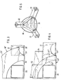
- Fig. 1 eine perspektivische Darstellung der eine Containerecke bildenden, mit einem Eckbeschlag verschweissten Profilelemente;
- Fig. 2 eine Seitenansicht der Anordnung nach Fig. 1;
- Fig. 3 und 4 Varianten der in Fig. 2 gezeigten Anordnung; und
- Fig. 5 eine perspektivische Ansicht einer Containerecke von innen zur Darstellung einer anderen Ausführungsform eines Knotenstücks.
- 1 shows a perspective illustration of the profile elements forming a container corner and welded with a corner fitting;
- FIG. 2 shows a side view of the arrangement according to FIG. 1;
- 3 and 4 variants of the arrangement shown in Fig. 2; and
- Fig. 5 is a perspective view of a container corner from the inside to show another embodiment of a node piece.
In Figur 1 und 2 sind die einen unteren linken Eckbereich eines Frachtcontainers bildenden Konstruktionselemente gezeigt, zu denen ein Eckbeschlag 30, drei Teile eines Containerrahmens bildende senkrecht zueinander verlaufende Profilelemente 31,32,33 und ein den Eckbeschlag verstärkendes Knotenstück 34 (nur in Fig. 2 gezeigt) gehören. Der Eckbeschlag besteht, wie oben erläutert, aus drei senkrecht zueinander verlaufenden Wandelementen 21, 22, 23, die gemeinsam eine Ecköffnung 24 bilden. Der Eckbeschlag 30 kann aus einem ebenen Zuschnitt durch Kanten und Verschweissen oder auch durch Pressen, Ziehen oder einen sonstigen Verformungsvorgang hergestellt sein. Bei dem Knotenstück 34 handelt es sich um dasjenige Materialstück, das beim Ausschneiden der Ecköffnung 24 aus dem Eckbeschlag 30 anfällt. An den drei Kanten weist der Eckbeschlag 30 ferner jeweils ein in beiden aneinanderstossenden Wandelementen ausgeschnittenes Kantenloch 25 auf.1 and 2 show the structural elements forming a lower left corner region of a freight container, for which a corner fitting 30, three elements of a container frame forming
Die drei Profilemente 31, 32, 33 sind in die Kantenbereiche des Eckbeschlags 30 so weit eingeschoben, dass sie kurz vor der Ecköffnung 24 enden. Sie weisen ihrerseits ebenfalls jeweils ein Kantenloch 26 auf, das mit dem entsprechenden Kantenloch 25 des Eckbeschlags 30 im wesentlichen fluchtet. In dieser Stellung sind die Profilelemente 31, 32, 33 mit dem Eckbeschlag 30 an den in Figur 2 angedeuteten Stellen verschweisst. Das Knotenstück 34 ist so eingesetzt, dass seine beiden vertikalen Seitenflächen teilweise an den vertikalen Innenflächen der Profilelemente 31 und 33 anliegen und dort ebenfalls verschweisst sind. Die Verbindung zwischen dem Knotenstück 34 und dem vertikalen Profilelement 32 kann bei Bedarf über ein (in den Zeichnungen nicht dargestelltes) zusätzliches Bauelement erfolgen. Sofern die einander benachbarten senkrecht verlaufenden Kanten des Knotenstücks 34 und des vertikalen Profilelements 32 nicht zu stark abgerundet sind, kann auch eine unmittelbare Verschweissung der beiden Teile an diesen Kanten vorgenommen werden.The three
Die Profilelemente 31, 32, 33 sind als Hohlprofilelemente mit im wesentlichen quadratischem Querschnitt gestaltet. Die Ecköffnung 24 des Eckbeschlags 30 wird von drei in den einzelnen Wandelementen 21,22,23 liegenden im wesentlichen quadratischen Ausschnitten gebildet, deren von der gemeinsamen Ecke abgewandte Ecke gerundet ist. Diese Quadratflächen sind etwas grösser als der lichte Querschnitt der Profilelemente 31, 32,33, so dass die Profilelemente als Staplerkanäle verwendet werden können und mit ihrem vollen Querschnitt durch die Ecköffnung 24 hindurch zugänglich sind. Die äussere Form der den Eckbeschlag 30 bildenden drei Wandelemente 21, 22 und 23 entspricht jeweils einem Kreisquadranten, wobei die Kreismittelpunkte in der (gedachten) Ecke des Eckbeschlags 30 zusammenfallen.The
Ist ein Container an allen seinen acht Ecken gemäss der Darstellung in Figur 1 und 2 aufgebaut, so lässt er sich mittels eines Gabelstaplers in jeder beliebigen Lage und von jeder Seite her anheben, da die Staplerarme in jeder der drei Richtungen durch jeden Eckbeschlag hindurch in den von dem betreffenden Profilelement 31, 32, 33 gebildeten Staplerkanal eingeführt werden können. Wegen der aus Symmetriegründen quadratischen Staplerkanal-Querschnitte ist es günstig, wenn auch die Gablerarme bzw. Gabelzinken quadratischen Querschnitt haben. Dies ist gegenüber den üblichen flachen Zinkenquerschnitten wegen der erhöhten Biegesteifigkeit von Vorteil.If a container is set up at all of its eight corners as shown in Figures 1 and 2, it can be lifted in any position and from any side by means of a forklift, since the forklift arms go through each corner fitting in each of the three directions can be introduced by the
Zur Handhabung des Containers mittels Gabelstaplers können die Staplerarme in die beiden unteren oder die beiden oberen Eckbeschläge und die dahinter liegenden Profilelemente über eine entsprechend grosse Länge eingeführt werden. Statt dessen ist es auch möglich, zwei wesentlich kürzere Gabelarme oder Dorne in die beiden oberen Eckbeschläge und Profilelemente über eine verhältnismässig kurze Länge einzuführen und durch Arretierungsstifte zu sichern, die durch die Kantenlöcher 25, 26 hindurch in entsprechende Ausnehmungen in den Staplerarmen eingeführt werden oder in entsprechendem Abstand von staplerseitigem Ende der Arme fest mit diesen verbunden sind. Weiterhin ist es auch möglich, vergleichsweise kurze Dornen in alle vier dem Gabelstaplerzugewandten Eckbeschläge und die dahinter liegenden Profilelemente einzuführen, wobei auch in diesem Fall mit Seitenspreadern gearbeitet wird. Die Reibung der vier Dorne innerhalb der vier Profilelemente sorgt in diesem Fall für eine noch sicherere Halterung des Containers am Gabelstapler.To handle the container using a forklift, the fork arms can be inserted into the two lower or the two upper corner fittings and the profile elements behind them over a correspondingly large length. Instead, it is also possible to insert two significantly shorter fork arms or mandrels into the two upper corner fittings and profile elements over a relatively short length and to secure them with locking pins which are inserted through
Schliesslich können durch die unteren Eckbeschläge und miteinander fluchtenden Hohlprofilelemente von mehreren hintereinander stehenden Containern zwei parallele Koppelstangen hindurchgeführt werden. Eine derartig gekoppelte Einheit könnte ohne Plattform oder Chassis auf Achselemente gestellt werden. Die mit diesem Konzept erzielte Gewichtsersparnis ist offenkundig.Finally, two parallel coupling rods can be guided through the lower corner fittings and mutually aligned hollow profile elements from several containers standing one behind the other. Such a coupled unit could be placed on axle elements without a platform or chassis. The weight saving achieved with this concept is obvious.
Anstelle der in Figur 1 und 2 gezeigten Profilelemente mit im wesentlichen quadratischem Hohlprofil können auch solche mit kreisförmigem Hohlprofil verwendetwerden. In diesem Fall müssen auch die Arme oder Zinken des Gabelstaplers bzw. Seitenspreaders kreisförmigen Querschnitt haben, was für die Handhabung von Papierrollen oder dergleichen bekannt ist.Instead of the profile elements shown in FIGS. 1 and 2 with a substantially square hollow profile, those with a circular hollow profile can also be used. In this case, the arms or tines of the forklift or side spreader must also have a circular cross section, which is known for the handling of paper rolls or the like.
Ferner ist es auch möglich, als Profilelemente 31,32,33 solche mit L-Profil zu verwenden, die in üblicher Weise so angeordnet sind, dass ihre Kanten die Aussenkanten des Containerrahmens bilden. In einem solchen Fall können nur die entsprechend der jeweiligen Lage des Containers oberen beiden Profilelemente als Staplerkanäle verwendet werden.Furthermore, it is also possible to use those with L-profile as
Zum Heben des Containers mittels Kranhaken wird dieser durch die Ecköffnung 24 hindurch derart eingeführt, dass seine Spitze durch diejenige Kantenöffnung 25, 26 austritt, die in Zugrichtung des Kranseiles liegt. Die in Figur 1 und 2 gezeigte abgerundete Form der im übrigen durch Quadratflächen gebildeten Ecköffnung 24 bewirkt dabei, dass sich der Kranhaken mit seinem dem Seilangriffspunkt benachbarten Abschnitt in die Rundung schmiegt und dadurch in derjenigen Stellung zentriert wird, in der er gegen ein Herausfallen bei schlaffem Seil gesichert ist.To lift the container by means of a crane hook, it is inserted through the corner opening 24 in such a way that its tip exits through the edge opening 25, 26 which lies in the pulling direction of the crane cable. The rounded shape shown in FIGS. 1 and 2 of the corner opening 24, which is otherwise formed by square surfaces, causes the crane hook to nestle into the rounding with its portion adjacent to the rope application point and thereby be centered in the position in which it prevents it from falling out when the slack Rope is secured.
Beim Verkoppeln neben- oder aufeinander liegender Container lassen sich Koppelelemente durch die Ecköffnungen 24 oder durch die Kantenöffnung 25, 26 der jeweils unmittelbar benachbarten Eckbeschläge 30 der beiden Container einführen, wobei diese Koppelelemente zusätzlich durch die jeweils anderen Löcher bzw. Öffnungen hindurch fixiert werden können.When coupling adjacent or stacked containers, coupling elements can be through the
Die Ausführungsform nach Figur 3 unterscheidet sich von der nach Figur 1 und 2 dadurch, dass die Ecköffnung 24' von drei Viertelkreisbögen gebildet ist, deren Radius im wesentlichen gleich der Diagonale des lichten Querschnitts der Profilelemente 31, 32, 33 ist. Die Wandelemente, von denen in Figur 3 insbesondere das Wandelement 23 zu sehen ist, sind dabei auf einen verhältnismässig schmalen Ring reduziert, der nur bis zu einem Teil der in den Profilelementen 31, 32 vorgesehenen Kantenlöcher 26 verläuft. In diesen Kantenbereichen ist der Eckbeschlag nach Figur 3 mit Kantenausschnitten 25' versehen.The embodiment according to FIG. 3 differs from that according to FIGS. 1 and 2 in that the corner opening 24 'is formed by three quarter-circle arcs, the radius of which is substantially equal to the diagonal of the clear cross section of the
Während bei dem Eckbeschlag 30 nach Figur 1 und 2 die Kantenlöcher 25, 26 in den beiden aneinanderstossenden Wandelementen jeweils halbkreisförmig ausgebildet sind (wobei das im Eckbeschlag vorgesehene Kantenloch 25 zur Aufnahme von Toleranzen in der gegenseitigen Ausrichtung etwas grösser ist als das Kantenloch 26 in den Profilelementen), ist es auch möglich, das Kantenloch 26' in den Profilelementen durch einen rechteckigen oder schrägen Ausschnitt zu bilden, wie dies in Figur 3 durch gestrichelte Linien angedeutet ist. Ein gerader über die Kante des Profilelements verlaufender Ausschnitt ist dabei herstellungstechnisch besonders günstig.While in the corner fitting 30 according to FIGS. 1 and 2, the edge holes 25, 26 in the two abutting wall elements are each semicircular (the
In Figur 3 ist kein Knotenstück gezeigt. Ferner sind die Profilelemente nur über ein kurzes Stück in den Eckbeschlag 30' eingeführt. Diese Gestaltung der Containerecke kommt daher mit wenig Material aus und ist leicht, was für Kleincontainer brauchbar und günstig sein kann.In Figure 3, no knot is shown. Furthermore, the profile elements are only inserted into the corner fitting 30 'over a short distance. This design of the container corner therefore requires little material and is light, which can be useful and inexpensive for small containers.
In der in Figur 4 gezeigten weiteren Variante sind die Wandelemente des Eckbeschlags 30" auf eine noch geringere Materialbreite reduziert. In diesem Fall endet der Eckbeschlag ausserhalb der in den Profilelementen 31,32 vorgesehenen Kantenlöcher 26". Zur Erhöhung der Steifigkeit ist dabei wieder ein Knotenstück 34 vorgesehen, das in diesem Fall so eingesetzt ist, dass seine dem Betrachter zugewandte senkrechte Fläche an dem Wandelement 23" anliegt und mit diesem verschweisst ist, während die beiden übrigen Flächen des Knotenstücks 34 mit der oberen Fläche des Profileiements 31 bzw. der rechten inneren Fläche des Profilelements 32 verschweisstsind. In diesem Fall lässt sich eine Verbindung zwischen Knotenstück 34 und dem dritten Profilelement 33 wiederum über ein zusätzliches (nicht gezeigtes) Bauelement erreichen.In the further variant shown in FIG. 4, the wall elements of the corner fitting 30 "are reduced to an even smaller material width. In this case, the corner fitting ends outside the edge holes 26" provided in the
In Figur 5 ist ein anderes Knotenstück 35 gezeigt, das im wesentlichen aus einem gleichseitigen ebenen Flächenstück mit an den drei Seiten angekanteten trapezförmigen Abschnitten besteht. Die gleichseitige Dreiecksfläche verläuft dabei im wesentlichen senkrecht zur Raumdiagonale der von den drei Profilelementen 31, 32, 33 definierten Containerecke. Die trapezförmigen Abschnitte sind gegenüber der gleichseitigen Flächen zur Ecke hin gekantet, so dass ihre Seitenkanten an den Innenflächen der Profilelemente 31, 32, 33 anliegen und mit diesen verschweisst sind. Mit dem Knotenstück 35 wird eine gleichmässige und sichere Versteifung gegenüber allen drei Profilelementen erreicht.Another
Die oben beschriebenen Gestaltungsmerkmale der drei in den Zeichnungen gezeigten Ausführungsbeispiele können je nach Bedarf variiert werden. So kann auch in der Ausführungsform nach Figur 3 ein Knotenstück verwendet werden. In jedem Fall kann das Knotenstück entsprechend Figur 2 und 4 oder entsprechend Figur 5 gestaltet sein. Ferner kann der Eckbeschlag in sämtlichen Fällen anstelle der gezeigten Kreisquadranten aus dreieckigen oder auch quadratischen Wandelementen aufgebaut sein. In ähnlicher Weise kann die Ecköffnung 24 des Eckbeschlags in jedem Fall aus quadratischen Ausschnitten mit gerundeter Ecke gemäss Figur 1 oder 2 oder aus viertelkreisbogenförmigen Ausschnitten gemäss Figur 3 und 4 oder auch aus dreieckigen Ausschnitten gebildet sein.The above-described design features of the three exemplary embodiments shown in the drawings can be varied as required. A knot piece can also be used in the embodiment according to FIG. 3. In any case, the node piece can be designed according to Figures 2 and 4 or according to Figure 5. Furthermore, in all cases, the corner fitting can be constructed from triangular or square wall elements instead of the circular quadrants shown. Similarly, the corner opening 24 of the corner fitting can in any case be formed from square cutouts with a rounded corner according to FIG. 1 or 2 or from quarter-circle-shaped cutouts according to FIGS. 3 and 4 or from triangular cutouts.
Claims (10)
Applications Claiming Priority (2)
| Application Number | Priority Date | Filing Date | Title |
|---|---|---|---|
| DE3239620 | 1982-10-26 | ||
| DE19823239620 DE3239620C2 (en) | 1982-10-26 | 1982-10-26 | Freight container |
Related Parent Applications (1)
| Application Number | Title | Priority Date | Filing Date |
|---|---|---|---|
| EP83105464.8 Division | 1983-06-01 |
Publications (2)
| Publication Number | Publication Date |
|---|---|
| EP0215217A1 EP0215217A1 (en) | 1987-03-25 |
| EP0215217B1 true EP0215217B1 (en) | 1988-03-30 |
Family
ID=6176640
Family Applications (1)
| Application Number | Title | Priority Date | Filing Date |
|---|---|---|---|
| EP19860109115 Expired EP0215217B1 (en) | 1982-10-26 | 1983-06-01 | Freight container |
Country Status (3)
| Country | Link |
|---|---|
| EP (1) | EP0215217B1 (en) |
| DE (1) | DE3239620C2 (en) |
| HK (1) | HK3789A (en) |
Families Citing this family (3)
| Publication number | Priority date | Publication date | Assignee | Title |
|---|---|---|---|---|
| DE3501969A1 (en) * | 1985-01-22 | 1986-07-24 | Westerwaelder Eisen Gerhard | DEVICE FOR LOCKING A CONTAINER |
| FR2649430B1 (en) * | 1989-07-07 | 1995-09-08 | Bardou Christian | MODULAR TRANSPORTABLE CONSTRUCTION |
| US5257440A (en) * | 1989-07-07 | 1993-11-02 | Christian Bardou | Portable modular structure |
Family Cites Families (3)
| Publication number | Priority date | Publication date | Assignee | Title |
|---|---|---|---|---|
| DE2942104A1 (en) * | 1979-10-18 | 1981-05-07 | Graeff Heinrich | Accessible and transportable building material container - is made from trapeze shaped angle sections inserted into square frame |
| EP0054881B1 (en) * | 1980-12-23 | 1984-10-24 | Westerwälder Eisenwerk Gerhard GmbH | Corner fittings for freight containers |
| DE3222763C1 (en) * | 1982-06-18 | 1983-10-20 | Westerwälder Eisenwerk Gerhard GmbH, 5241 Weitefeld | Corner bracket for freight containers |
-
1982
- 1982-10-26 DE DE19823239620 patent/DE3239620C2/en not_active Expired
-
1983
- 1983-06-01 EP EP19860109115 patent/EP0215217B1/en not_active Expired
-
1989
- 1989-01-12 HK HK3789A patent/HK3789A/en unknown
Also Published As
| Publication number | Publication date |
|---|---|
| DE3239620A1 (en) | 1984-05-03 |
| DE3239620C2 (en) | 1985-01-24 |
| EP0215217A1 (en) | 1987-03-25 |
| HK3789A (en) | 1989-01-20 |
Similar Documents
| Publication | Publication Date | Title |
|---|---|---|
| EP0097269B1 (en) | Corner fittings for freight containers | |
| DE2437551A1 (en) | PLASTIC PALLET | |
| AT401915B (en) | Container having a base and side-wall parts which are connected pivotably thereto | |
| AT411991B (en) | CONTAINER MULTIPLE PANELS | |
| EP0515819A2 (en) | Transport and storage container | |
| DE2507709A1 (en) | PALLET FOR ACCEPTING LOADED GOODS | |
| DE3511321A1 (en) | Stackable containers | |
| DE1965664A1 (en) | Frame for an accumulator battery | |
| EP2727854B1 (en) | Device for aligning a stack of containers | |
| DD289504A5 (en) | unit | |
| EP3636559B1 (en) | Stackable box | |
| DE3200216A1 (en) | SEALABLE AND STACKABLE CONTAINER | |
| DE102007035613A1 (en) | Folding trunk hinge, has outer hinge with top set as hinge roof plate, and two bearing troughs bearing two inner hinge flaps inner and outer sides of outer hinge in direction of breadth of out hinge flaps | |
| DE19500173A1 (en) | Foldable flat frame | |
| DE2612245C2 (en) | Barrel-like container | |
| EP0215217B1 (en) | Freight container | |
| EP0669259B1 (en) | Stackable, nestable container | |
| DE2836093C2 (en) | Stake pallet | |
| EP0440844A1 (en) | Carrying crates with means to detachably connect carrying crates | |
| EP0483605A2 (en) | Arrangement for securing a unit load | |
| WO1997041037A1 (en) | Articulated arrangement for the pivotable wall sections of a container | |
| EP3626646B1 (en) | Stackable tray | |
| DE4028846C1 (en) | ||
| DE2128297C3 (en) | palette | |
| CH695335A5 (en) | Stackable container has baseplate, four side walls extending to a widened opening and at least one stirrup movably arranged in the area of the side walls |
Legal Events
| Date | Code | Title | Description |
|---|---|---|---|
| PUAI | Public reference made under article 153(3) epc to a published international application that has entered the european phase |
Free format text: ORIGINAL CODE: 0009012 |
|
| 17P | Request for examination filed |
Effective date: 19860717 |
|
| AC | Divisional application: reference to earlier application |
Ref document number: 97269 Country of ref document: EP |
|
| AK | Designated contracting states |
Kind code of ref document: A1 Designated state(s): BE FR GB IT NL SE |
|
| 17Q | First examination report despatched |
Effective date: 19870907 |
|
| GRAA | (expected) grant |
Free format text: ORIGINAL CODE: 0009210 |
|
| AC | Divisional application: reference to earlier application |
Ref document number: 97269 Country of ref document: EP |
|
| AK | Designated contracting states |
Kind code of ref document: B1 Designated state(s): BE FR GB IT NL SE |
|
| ITF | It: translation for a ep patent filed |
Owner name: ING. C. GREGORJ S.P.A. |
|
| ET | Fr: translation filed | ||
| GBT | Gb: translation of ep patent filed (gb section 77(6)(a)/1977) | ||
| PLBE | No opposition filed within time limit |
Free format text: ORIGINAL CODE: 0009261 |
|
| STAA | Information on the status of an ep patent application or granted ep patent |
Free format text: STATUS: NO OPPOSITION FILED WITHIN TIME LIMIT |
|
| 26N | No opposition filed | ||
| ITTA | It: last paid annual fee | ||
| PGFP | Annual fee paid to national office [announced via postgrant information from national office to epo] |
Ref country code: SE Payment date: 19900522 Year of fee payment: 8 |
|
| PGFP | Annual fee paid to national office [announced via postgrant information from national office to epo] |
Ref country code: BE Payment date: 19900601 Year of fee payment: 8 |
|
| PG25 | Lapsed in a contracting state [announced via postgrant information from national office to epo] |
Ref country code: SE Effective date: 19910602 |
|
| PG25 | Lapsed in a contracting state [announced via postgrant information from national office to epo] |
Ref country code: BE Effective date: 19910630 |
|
| BERE | Be: lapsed |
Owner name: WESTERWALDER EISENWERK GERHARD G.M.B.H. Effective date: 19910630 |
|
| PGFP | Annual fee paid to national office [announced via postgrant information from national office to epo] |
Ref country code: GB Payment date: 19920528 Year of fee payment: 10 |
|
| PGFP | Annual fee paid to national office [announced via postgrant information from national office to epo] |
Ref country code: NL Payment date: 19920630 Year of fee payment: 10 Ref country code: FR Payment date: 19920630 Year of fee payment: 10 |
|
| PG25 | Lapsed in a contracting state [announced via postgrant information from national office to epo] |
Ref country code: GB Effective date: 19930601 |
|
| PG25 | Lapsed in a contracting state [announced via postgrant information from national office to epo] |
Ref country code: NL Effective date: 19940101 |
|
| GBPC | Gb: european patent ceased through non-payment of renewal fee |
Effective date: 19930601 |
|
| NLV4 | Nl: lapsed or anulled due to non-payment of the annual fee | ||
| PG25 | Lapsed in a contracting state [announced via postgrant information from national office to epo] |
Ref country code: FR Effective date: 19940228 |
|
| REG | Reference to a national code |
Ref country code: FR Ref legal event code: ST |
|
| EUG | Se: european patent has lapsed |
Ref document number: 86109115.5 Effective date: 19920109 |