EP0214906A1 - Selective ejection conveyor - Google Patents
Selective ejection conveyor Download PDFInfo
- Publication number
- EP0214906A1 EP0214906A1 EP86401913A EP86401913A EP0214906A1 EP 0214906 A1 EP0214906 A1 EP 0214906A1 EP 86401913 A EP86401913 A EP 86401913A EP 86401913 A EP86401913 A EP 86401913A EP 0214906 A1 EP0214906 A1 EP 0214906A1
- Authority
- EP
- European Patent Office
- Prior art keywords
- diverting
- articles
- diverting device
- article
- driven
- Prior art date
- Legal status (The legal status is an assumption and is not a legal conclusion. Google has not performed a legal analysis and makes no representation as to the accuracy of the status listed.)
- Granted
Links
Images


Classifications
-
- B—PERFORMING OPERATIONS; TRANSPORTING
- B65—CONVEYING; PACKING; STORING; HANDLING THIN OR FILAMENTARY MATERIAL
- B65G—TRANSPORT OR STORAGE DEVICES, e.g. CONVEYORS FOR LOADING OR TIPPING, SHOP CONVEYOR SYSTEMS OR PNEUMATIC TUBE CONVEYORS
- B65G47/00—Article or material-handling devices associated with conveyors; Methods employing such devices
- B65G47/52—Devices for transferring articles or materials between conveyors i.e. discharging or feeding devices
- B65G47/64—Switching conveyors
- B65G47/644—Switching conveyors by a pivoting displacement of the switching conveyor
- B65G47/645—Switching conveyors by a pivoting displacement of the switching conveyor about a horizontal axis
- B65G47/647—Switching conveyors by a pivoting displacement of the switching conveyor about a horizontal axis the axis being perpendicular to the conveying direction
Definitions
- the invention relates to ejection devices for use in a production line.
- This invention may be used with conveyers having a plurality of rows of articles and especially food articles.
- Prior Art pivoting conveyor members are difficult to maintain when a belt breaks, they may be undesirable for use in a high production system where there is only limited storage for articles coming off the conveyor belts, and which articles cannot be processed during the maintenance time.
- the Prior Art pivoting conveyor belts do not provide for rapid replacement of an integral belt, but would require use of a spliced belt which is stretched around the rollers and then joined in place. Such spliced belts do not last as long as integral belts which have been formed as a continuous band.
- the patent number 3,404,775 to McClellan shows in Figure 2 a linearly-movable arm 22 which causes pivoting of an arm 18 which in turn causes pivoting of a conveyor belt 25. Pivoting causes dropping of a brick between two adjacent conveyor belts, as seen in figures 2 and 3. It is noteworthy from an inspection of figures 3 and 4 that two different pivoting conveyor belt sections must be pivoted in order for a brick 51 to drop. This is a result of the parallel adjacent members 56, 58 and 60, 62, as well as members 57 and 59 which are adjacent to members 61 and 65. These pivoting conveyor belt segments can be actuated by electrical,pneumatic, or other signals to drop selected bricks upon crosswise- moving belts to classify bricks according to color, finish, or other characteristics.
- this patent does not teach or suggest mounting a plurality of closely-spaced conveyor belt members for selective pivoting (or other movement) out of a conveyor belt path to permit dropping of selected articles, wherein the closely-spaced conveyor belts are driven in such c manner as to render any single one of the closely-spaced conveyor belts replaceable with a continuous band conveyor belt rather than a spliced conveyor belt.
- FIG. 4 The patent no. 4,426,047 to Fisher teaches a pivoting conveyor belt segment having an actuator 14, for clearing spoiled items from an overlapped stream of paper products.
- a three-flight conveyor belt transporting system is rocked bodily, so as to have an upper and a lower position, so that a continuous stream of spoiled items can be transferred downwardly under the next flight to a separate delivery.
- Figures 1 and 2 are illustrative, and show a sensor 17 such as a photoelectric cell together with a processing unit 18 capable of actuating a solenoid of valve 15, so as to drive cylinder 14.
- a plurality of commonly-driven conveyor belt segments which are selectively movable out of a conveying relationship and which are so connected with a drive means that any single belt can be replaced with a continuous belt without removing any other parts.
- the patent number 4,424,966 to Chandhoke teaches a cylinder 144 which causes pivoting of a conveyor belt segment 32 between rolls 46 and 54, between an upper conveying and a lower position.
- a member 134, 136 which is a rake, forms a bridge between the pulleys 46 and the T -shaped member 98 to support the books from the binder 1 2 on the upstream portion 30 of the conveyor 20.
- the articles so supported by the rake are thus in place ready to move the conveyor end portion 32 returns to its horizontal position.
- the invention is a selective diverting device for diverting an individual cookie from one conveyor belt path to another location. It is preferably used in combination with a sensing device, such as a weigher, optical sensor, color sensor, or the like, the sensor selecting out "rejected" cookies and actuating the diverting member.
- a sensing device such as a weigher, optical sensor, color sensor, or the like
- the diverting member itself comes in three embodiments, all similar, and a fourth embodiment which is somewhat different.
- the first three embodiments include a pivotable conveyor-belt device which is automatically actuated (as by a piston or the like) to pivot out of the main conveyor belt path when a "reject" article is located thereon.
- the "reject" conveyor belt is a retractable device, not pivotable, and is for articles having a greater length than the spacing between two rollers (since relatively large gaps occur in this embodiment).
- a drive means which forms a separate aspect of the invention to be searched.
- a single long drive shaft has multiple gears, each gear engaging a driven gear on the diverting belts. This arrangement is necessary so that continuous, rather than spliced, conveyor belts can be stretched into place for maintenance and repair operations.
- there is a clearance between the drive shaft and the nearest portion of the conveyor belt so that a new conveyor belt can be snapped over the rollers for replacement at any time, without removal of any of the other diverting belt parts.
- a pneumatic cylinder is selectively actuatable to cause pivoting of a support member about the drive shaft.
- a drive shaft has a drive gear which is in driving relation to a driven gear, the driven gear being operatively attached to a roller for a belt.
- Other rollers are provided, as well as a tensioning roller for maintaining tension in the belt.
- Each of the other rollers completing the conveyer belt circuit are rotatably mounted upon the support plate.
- An end of the pneumatic cylinder is pivotably connected to the support member, and the other end of the pneumatic cylinder is pivotably connected to a fixed support.
- the end of the driven cylinder which supports the belt is open, as are the other rollers which support the belt, so that a conveyer belt can be removed or placed over the rollers without disassembly of any of the rollers or other parts.
- a continuous conveyer band such as a nylon belt, can be used for prolonging a period between required belt changes due to worn or broken bands.
- a new continuous belt can be used to replace a broken belt without disassembly of any other parts.
- the diverting member is placed in bridging relationship between two conveyers belts, each conveyer belt having multiple rows and columns of articles thereon.
- a sensed attribute of the articles such as overweight or underweight, color of the article, or sensed information regarding the shape and composition of the article, among other measurable attributes
- an individual article can be ejected by pivoting motion of the selective diverting device away from the bridging relationship, so that the selected article passes in between the two stationary conveyor belts, whereupon the diverting member is returned to its bringing relationship.
- a tensioning roller is omitted, and instead of flat conveyer belts, round conveyer members having circular cross-sectional shapes, are used.
- the support member is not mounted about the drive shaft, but rather a slotted guide member is used which is fixed to a stationary support.
- the bridging portion of the conveyer belt is an end of the conveyer belt which is curved about an end roller.
- the support plate rotatably supports the end roller as well as the driven roller, the support plate having a follower member attached thereto for following the slot of the slotted member.
- Another plate can be used to pivotably fix the drive roller to the driven roller during pivoting motion thereof.
- An actuating member such as a pneumatic cylinder can be used to position the end roller either in bridging relationship or in non-bridging relationship between two stationary conveyer belts.
- the actuating member causing linear movement of the support member and the driving gear attached about the drive shaft remains in contact with the driven gear throughout.
- a small amount of angular motion of the support plate occurs due to the motion of the driven gear relative to the drive gear.
- the conveyor belt support rollers namely the end roller and the driven roller, are rotatably mounted to the support member such that the conveyer belt can be removed and replaced without disassembly of any other parts.
- a computer or signal processor can be used in combination with any known type of sensor appropriate for the articles conveyed, in order to selectively actuate any one or ones of the diverting members to permit diversion of individual selected articles.
- FIG. 1 shows the front elevational view of a diverting member 1.
- the diverting member 1 includes a support plate 20.
- the support plate 20 is closely rotatably mounted about a drive shaft 50.
- the support plate 20 is pivotally connected by a pin 13 to a collar 7.
- the collar 7 is supported by a shaft 8 and an air cylinder 9.
- the air cylinder 9 in the preferred embodiment is a Clippard pneumatically-driven cylinder UDR-12 having a 3/4 inch bore and a 2-inch stroke.
- the air cylinder 9 is preferably double acting so as to provide a positive force for moving the shaft 8 in both directions.
- the air cylinder 9 is pinned at its lower end by a pin 14 to a support member 17 connected to a fixed support 18 represented schematically in Figure 1.
- the air cyclinder 9 has an upper air inlet 110 and a lower air inlet 12. Air flow is indicated schematically by arrow 22 and arrow 23 for respective inlets 110 and 12.
- the diverting member 1 is in bridging relationship between a downstream conveyor belt 2 and an upstream conveyor belt 3.
- the conveyor belt 2 has a belt 19, and the conveyor belt 3 has a belt 21.
- Both of the belts 19, 21 move with a speed W as indicated by the arrows in Figure 1; however, it is contemplated as being within the scope of the present invention that the conveyor belts 19 and 21 may move differing speeds, which differing speeds can be used to adjust the spacing between articles. It is also contemplated as being within the scope of the present invention that the conveyor belt 4 can move at different speeds than the belts 19 and 21, if desired.
- an article 10, such as candy bar or other article has passed from conveyor belt 21 and onto a conveyor belt which is part of the diverting member 1.
- the conveyor belt 4 is supported by a roller 11 and a roller 12, both of which are rotatably mounted for rotation about each respective roller axis, upon the plate 20. Additionally, a tensioning roller 13 is slidably and rotatably mounted for contact with the belt 4 by a spring member 15 which is fixably connected at its other end to a support block 16. The support 16 in turn is fixed to the pipe 20.
- the tensioning roller 13 is not necessary and omission of a tensioning roller from any embodiment shown,_ or inclusion with any embodiment, is contemplated as being within the scope of the present invention.
- a gear 6 is rotatably fixed about its axis to the plate 20, and is fixedly connected against relative rotation to a driven roller 5. Any alternative means of connection can also be used, such as reduction gearing, or other connecting means between the gear 6 and the roller 5.
- a drive gear 3 is in contact with the driven gear 6, the drive gear 3 being fixedly connected as by a pin, welding, or the like to a drive shaft 50. Thus, the drive gear 3 rotates relative to the plate 20 but gear 3 is fixed to the snaft 50 for rotation therewith.
- any actuating device can be used instead, such as a solenoid, a magnetically-actuated device, or a mechanical device, or any other device capable of moving the device 1 between two positions.
- the air supply to either the top or the bottom air cylinder 9 is supplied from an air supply.
- Flow into or out of the port 110 and 12 is preferably valved by a solenoid-actuated valve or the like.
- An air cylinder 9 has been chosen in the preferred embodiment for maintainability and reliability, however any other actuating devices can be used in the present invention.
- any support structure can be used instead, including curved, prismatic, or other shapes; and any forming means can be used for the member 20 or alternatives thereof, including but not limited to molding, casting, cutting, metalworking, or other forming means.
- the support plate 20 is preferably made of strong, light-weight material such as aluminum, but it can also be made of steel, plastic, wood, or any other material sufficiently strong to support rollers and a conveyor belt.
- the rollers are preferably any conventional roller formed of wood, plastic, steel, aluminum, or the like and are mounted for rotation by bearing members.
- bearing members may include, for example, a low-friction material such as nylon or Teflon, ball bearings, journal bearings, or any other type of bearing known to those skilled in the bearing art.
- the belt 4 is preferably a flat urethane endless belt, such as those well-known in the art. However, any type of belt and belt material, including woven cloth, plastic, rubber, steel mesh or the like can be used with the present invention.
- seamed belts are preferred in the present invention for greater reliability and longer life
- seamed belts can be used as well.
- Such seamed belts are usually made by splicing or by similar operations, and are generally inherently weaker and have a shorter life than endless belts which have no seams.
- Figure 1 shows the second position of the diverting member 1 in dotted outline.
- the gears 3 and 6 have meshing teeth (the teeth or omitted from the drawings for clarity).
- the gear 6 pivots to its position indicated by 6', which remains in toothed, engaging contact with the gear 3.
- the gear 3 does not rotate with the plate but rather with the shaft. Therefore, the roller 3 remains in driving relationship with the gear 6 throughout the pivoting operation.
- a subsequent article 10' passes between the conveyors 2 and 3 as indicated by the position shown in dotted outline in Figure 1.
- the article 10' is indicated as having a velocity V, which is a combination of a forward velocity W and a downward component of velocity due to gravity.
- the diverted article can fall downwardly into any type of receptace. Furthermore, the diverted article 10' can fall upon a chute, another conveyor belt, or a shredder, among other devices, for further processing. All such further steps are contemplated as being within the scope of the present invention.
- the diverting member 1 remains in its initial position shown in solid outline in Figure 1 until a signal is received to divert an article 10', whereupon a diverting member 1 is moved to its second position as shown in dotted outline. After the article has been diverted, the air cylinder 9 is actuated to return the diverting member 1 to its first position as shown in solid outline.
- Figure 2 is a top elevational view of the diverting member 1, and the conveyor belts 2 and 3.
- a sensing device 24 for sensing each of the individual ones of the articles 10, and a signal processor 26 for processing signals received from the sensor 24.
- a controller 28 is also schematically indicated, for controlling a mechanism 30 which selectively actuates any one or ones of the air cylinders 9 to act upon respective diverting members 1.
- an air supply 31 for supplying air to the air cylinders 9. Any air supply source, such as a storage tank, compresser, or the like can be used in the present invention.
- the conveyor belts 2 and 3, as well as the diverting members 1, are shown as being broken way in dotted outline along a longitudinal centerline.
- the broken away portion indicates that an arbitrary number of additional members or additional width of conveyor belt can be used, as appropriate. Also, a lesser number of rows and a lesser number of diverting members, as well as a lesser width of conveyor belt, can be used. All such variations are contemplated as being within the scope of the present invention.
- twenty four diverting members are arranged to be driven simultaneously by a single shaft 50. Each diverting members 1 receives articles from a single row of articles from the conveyor belt 21.
- the signal processor 26 When an article 10 to be diverted is sensed by the sensing member 24, the signal processor 26, having received signals along the pathway 25, determines the appropriate time for actuating a diverting device 1, and also selects one of the diverting devices 1 to be actuated. More than one diverting member 1 can be actuated selectively simultaneously, depending upon the articles 10 arriving at the diverting devices 1.
- the signal processor 26 takes into account the belt speed W of the belt 21, the position of the sensed article 10 which is to be diverted, and computes the desire to time at which the particular diverting device 1 is to be actuated.
- the signal processor 26 in the preferred embodiment is a computer. Instructions are preferably programmed into the computer, which preferably compares the sensed information about the articles 10 with predetermined "acceptable" range for the particular attribute sensed. For example, if color is sensed, a particular degree of browning, or a particular shade of color may be optimum, but there is ordinarily an acceptable range of browning, or of colors, such that outside the range, articles 10 are to be rejected. Additional sensors can also be employed, for example, weight, shape, composition, etc., which sensors also would send signals to the signal processor 26.
- any number of sensing devices can be used, such as an ultrasonic thickness measuring device, an infrared scanner, a television camara, a salinity meter, a magnetic sensor, or the like can all be used.
- the signal processor 26 accepting signals from all of the sensors and diverting articles 10 if the individual article 10 to be diverted fails to fall within the predetermined range of values sensed by the sensing devices 24.
- the signal processor 26 can preferably include a vision processor for comparing image information received from imaging devices such as television cameras or the like, and comparing the images to a number of predetermined acceptable images, for determining whether or not to divert a particular article 10.
- the signal processor computes, based upon empirical data, theoretical equations, ana other sensed imputs such as conveyor belt speeds of the belts 21 and 19, as well as any other conditions which are to be sensed, and sends its processed output signals (decisions) by pathway 27 to a controller 28.
- Controller 28 can also be a computer, or it can be an analog controlled device. Furthermore the controller 28 can be a part of the signal processor 26 if desired.
- the controller 28 supplies signals and/or power to actuate individual ones of the diverting members 1 shown in Figure 2.
- Such controllers are well-known in the art, and any controller for selectively actuating one of a plurality of actuatable devices can be used with the present invention.
- the controller supplies electrical power to solenoids which control air flow to the individual air inlets 110 and 12 of the cylinder 9.
- actuator 9 controller 28 signal processor 26 and sensing devices 24 have been described and illustrated, the present invention is not limited thereto but encompasses any and all equivalent structures known to those skilled in the respective arts.
- the pathways 25, 27, and 29, as well as the air supply conduit 22, are schematically illustrated and would include any appropriate conduit for the device chosen.
- the conduits 25, 27 and 29 are preferably electrical cables or cords where the sensing devices 24 have electrical ouputs and where the signal processor 26 and the controller 28 have electrical operating elements.
- a fluidic computer might be used, or analog control elements could be used as well.
- Figure 3 is a sectional side view of a diverting member 1 taken along the line 3-3 of Figure 1. Also shown to the left in figure 3, in side elevational view partially broken away at the upper portion, is another diverting member 1, showing the nesting relationship of the adjacent diverting member 1 and also showing the clearance between an end of a belt-carrying roller 5 and the support plate 20 of the adjacent diverting member 1. Also shown broken way at each end is the drive shaft 50 which drives each of the respective gears 6 of the respective diverting members 1.
- the plate 20 has a collar portion 20 disposed about the shaft 50.
- a low-friction member 41 such as a nylon sleeve or the like, is fixed in between the collar of the member 20 in the shaft 50 to permit relative rotation between the shaft 50 and the plate 20.
- the plate 20 supports a shaft 51 which is fixed thereto, the shaft 51 rotatably supporting the roller 12.
- This is schematically indicated in figure 3, with a cross-section of the flat belt 4 being visable atop the roller 12 in figure 3.
- a portion of the belt 4, partially broken away at either end, is visible in figure 3 between roller 5 and 12.
- the roller 5 is mounted by bearings 46 to a shaft 44.
- An end member 45 retains the roller 5 in position along the shaft 44.
- a shaft 42 is connected to the shaft 44 as well as rotatably supporting the gear 6.
- the gear 6 meshes with the gear 3 which is pinned or welded to the shaft 50. Any means of attachment of the gear 3 may be used, such as keying, glueing, ultrasonic welding or the like, which are within the ambit of a skilled artisan.
- the collar portion of the plate 20 serves to maintain the plate 20 against angular movement relative to the shaft except for rotational movement within a plane perpindicular to the axis of the shaft as indicated in figure 1.
- the plate 20 can rotate about the shaft 50 in a single plane between the two positions shown in figure 1 namely the solid position and a.dotted-outll-ne position.
- the gear 3 is retained also by a collar 120 which prevents sliding movement along the shaft 50. There is a clearing between the top of the collar 120 and the belt 4 just above it as seen in figure 3. Thus, there is a clearance for replacing a belt 4, the clearance being between adjacent diverting members 1 as well as between the bottom of the roller 5 and the top of the collar portion of support member 20, as well as the top of the collar 120 as seen in figure 3.
- a belt can be placed around the rollers 11, 12, 13, and 5 without removal of any parts or elements of the diverting members 1, and does not require removal of the shaft 50. This is despite the very close spacing between adjacent diverting members 1 which is seen in figure 3. This close spacing of belts 4 atop the diverting members 1 is necessary where there are closely spaced articles arriving from the conveyor belt 21 (shown in figure 2).
- the roller 12 is mounted in a similar manner to the rollers 11 and 13, which is shown in figure 3 as including a support shaft 52 which is rotatable relative to the roller 12, and a stop member 53 which retains the roller 12 on the shaft 52.
- the shaft 52 can be made of a low-friction material such as Teflon, nylon, or the like, or it may include ball bearings or other bearing surfaces such as a journal bearing.
- the shaft 52 may be integral with the roller 12 and the shaft 51 then be made rotatable and journaled or otherwise made rotatable relative to the plate 20 within which it is received.
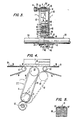
- FIG 4 is a front elevational view of another embodiment of an alternative diverting member 200.
- the diverting member 200 would be supported by a similar support plate 20 (not shown in figure 4 for clarity) and be actuated by a similar actuator 9.
- a similar support plate 20 not shown in figure 4 for clarity
- the curved end of a roller 60 having a belt thereacross is used.
- no tensioning roller is used, although if desired a tensioning roller can be provided.
- an article 10 which is overlying the roller 63 and having a portion in the gap between the rollers 62 and 63.
- the permissible range of articled sizes is indicated as follows.
- the smallest article has a length Y
- the longest article has a length X.
- articles can be diverted by pivoting of the diverting member 200 to the position shown in dotted outline in figure 4. In the dotted outline position the diverting member 200 is no longer in bridging relationship, and the article 10 can fall in the gap between 62 and 63. When the article has been diverted, the diverting member 200 is returned to its bridging position shown in solid outline.
- the belt 61 used with the diverting member 200 is preferably not a flat belt but rather a pair of round belts.
- Figure 5 shows a cross-sectional view of the mounting of the round belts on roller 60.
- the round belts 60', 61' together support an article 10.
- the article is preferrably an edible article such as a candy bar or a cookie or the like.
- any other article can be diverted by the diverting device 200, and the present invention is not limited to use with edible articles, candy bars, or cookies but encompasses all articles capable of being conveyed by any conveying means.
- Figure 6 is a front elevational view, partially in section, showing another embodiment of diverting member 1.
- a support plate 20 is used to maintain separation between rollers 75 and 76.
- a gear, hidden behind roller 76 but attached thereto for rotation therewith, is in engaging contact with gear 5 which is fixed for rotation with shaft 50.
- the shaft 50 is shown in section in figure 6, since the shaft 50 extends perpendicularly to the plane of the drawing for driving other diverting members.
- the diverting device 1 is in bridging relationship between a pair of rollers 72 and 73.
- a pnuematic cylinder 9 is fixed to the plate 20, in pivoting relationship by a pin 14.
- the pneumatic cylinder 9 is also pinned at its other end by a pin 74, so that, upon change in the distance between 14 and 74, the diverting member 1 pivots to the position shown in dotted outline in figure 6, as does the position of the pneumatic cylinder 9.
- the belt 77 carried by the rollers 75 and 76 in figure 6 is in bridging relationship between the rollers 72 and 73.
- the belts associated with the respective rollers 72, 75 and 76, and 73 need not move at the same respective speeds, but rather each can have its own speed.
- a single selected speed W has been selected for convenience, where the spacing between the articles is not to be changed. However, with different belt speeds, the spacings between articles can be increased or decreased by appropriate adjustment of the speeds of the various conveying members.
- the miscellaneous conventional elements such as bearings, and alike, can be those as shown in figure 3, or any other suitable bearing and other elements can be used, for example nylon bushings can be used for an anti-friction surface and the like.
- the plate 2 0 extends about the shaft 50, so that it is relatively rotatable thereto.
- the plate 20 portion passing about the shaft 50 is also relatively rotatable relative to the gear 5.
- Such arrangement can preferably be similar to that shown in figure 3, however any equivalant structure or alternatives which would be known to anyone having ordinary skill in the art, are contemplated as being within the scope of the present invention.
- the diverting member 1 in the solid-outline position the diverting member 1 is in bridging relationship and is capable of carrying articles from the conveyer belt supported by roller 73 and on to conveyer belt 77, once the articles pass to the conveyer belts supported by roller 72.
- the diverting member 1 In the dotted outline position of the diverting member 1, shown in figure 6, the diverting member 1 is no longer in bridging relationship between rollers 72 and 73, thereby permitting a selected article to pass between the rollers 72 and 73 and downward, rather than onto the conveyer belts supported by roller 72.
- the pneumatic cylinder 9 is preferrably of the double acting type, having a positive forward thrust as well as positive reverse thrust, similar to the pneumatic cylinder shown in figure 1 which has an inlet passage 110 and an inlet passage 12 for passage of air.
- solenoids or other controls can be used to control the action of the cylinder 9, so as to control the position of the diverting member 1 between its solid-outline position and its dotted-outline position.
- Such solenoids are actuated either manually or by a controller 28 such is as shown in figure 2.
- any known control means for moving a divertng member from its solid-outline position to a dotted outline position is contemplated as being within the scope of the present invention.
- Such means might include electromagnetic, mechanical, pneumatic, manual, or the like actuating means.
- FIG 7 is a front elevational view of an alternative embodiment of the diverting member according to the present invention.
- the diverting 600 has a roller 87 and belt 98 which bridges a gap between rollers 91 and 92.
- the belt 98 is preferably similar to belt 61' having a round cross-section, with grooves being formed in the roller 87 for receiving a pair of such belts 98 similar to that shown in figure 5.
- the support plate 20 pivotably supports rollers 87 and 5. No belt slack take-up roller is provided, although use of such take-up roller together with any other rollers desired is contemplated as being within the scope of the present invention. Also, the support plate 20 is not extended to encompass and surround the shaft 50, but rather terminates without encircling the shaft 50.
- a follower 80 which may be a fixed or rotatable member which is attached to the plate 20, is made and adapted to follow a slot 86.
- the slot 86 is formed in a guide plate 85, the guide plate 85 being fixed to a support which is stationary with respect to the parts shown. This support is indicated schematically in Figure 7.
- the slot 86 serves to guide the motion of the plate 20 as the follower descends to its lower most position indicated in dotted outline in Figure 7, and returns to its upper most position shown in solid outline in Figure 7.
- the dotted outline position of the roller 87 indicates that a gap is left between the rollers 91 and 92 to permit diverting of articles 10 passing from conveyor belt 21.
- Another support plate 420 passes about the shaft 50 and is pivotally connect, as by pinning, or the like, to the plae 20 at a location which is colinear with the axis of the roller 5.
- the plate 420 is pivotable about the shaft 50, and is moveable relative to the gear 3, and is pivotable relative to the plate 20.
- the plate 420 is pivotable relative to the gear 6 and relative to the roller 5.
- the plate 420 serves only to retain the gear 6 in contact with the gear 3 during movement of the gear 6 to its dotted outline position shown in Figure 7.
- An actuator such as actuator 9 shown in Figure 1, can be provided and attached either to the plate 20 or to the plate 420, since the linkage as shown including slot 86, plate 20 and plate 420, permit movement of the plate 20 and associated rollers from the solid outline position to the dotted outline position.
- the cylinder 9 can be pinned to a fixed support at one end and pinned for pivoting either to the plate 20 or to the plate 420 as desired, and such positioning of an actuating member such as the cylinder 9 would be a conventional design expedient known to any one having ordinary skill in the art.
- any conveyor belts or means may be used, including V -belts, round belts, or flat belts, perforated belts, woven belts, chain-mesh belts, and the like.
- any belt materials can be used. Such materials include steel mesh, Teflon-coated materials, nylon, urethane, rubber, or the like.
- Any control system can be used to actuate selectively the actuating members which are used in the present invention. Any and all actuating members capable of moving the diverting member 1 from one position to another are contemplated as being within the scope of the present invention. Furthermore, any selectively controllable control devices are contemplated as being within the scope of the present invention, and such control devices can be as discussed with respect to the signal processor 7, controller 28, and control device 30. Furthermore, any type of sensors can be used in determining which articles are to be diverted.
- Articles useable with the present invention include any food products, including candy bars, cookies, cakes, pies, breads, as well as non-food articles such as bricks, pages, boxes, electrical circuits, or any other articles capable of being selectively diverted from one conveying means to another.
- supply conveyor belts have been used for supplying articles to the diverting members shown in the present invention
- other members can be used as well, such as a flat surface from which articles are pushed by articles behind the pushed articles, such as an accumulator station, as well as a chute wherein articles slide along the chutes to the diverting members, as well as any other supply means capable of supplying articles to the diverting members 1.
- the diverting member 600 namely that any supply member can be used and not just the conveyor 21 shown in Figure 27.
- any other conveying means can be used to receive articles conveyed by the diverting while the diverting member is in its bridging position, and not just the conveyor belt 19 of the figures.
- a flat accumulator tray can be used or a sloping chute can be used permitting accumulated articles to slide therealong if such is desired.
- conveying means and devices can be used for supplying articles to the diverting members and for carrying articles away.
Abstract
Description
- The invention relates to ejection devices for use in a production line.
- This invention may be used with conveyers having a plurality of rows of articles and especially food articles.
- It is well-known to use pivoting numbers in connection with conveyer belts. The Prior Art pivoting members for use with conveyer belts cannot be used with multiple rows which are closely spaced, without suffering sufficient downtime loses do to breaking of an individual one of the conveyer belts. Maintenance of and replacement of a single individual conveyer belt on a pivoting section in the Prior Art would require removal of the entire drive shaft, making necessary extensive disassembly and re-assembly operations where the individual belt is for example between other conveyer belts rather than on the end. This lack of accessability, in a practical sense, limits the number of rows of articles which can be handled by such a pivoting conveyer system. Also, since the Prior Art pivoting conveyor members are difficult to maintain when a belt breaks, they may be undesirable for use in a high production system where there is only limited storage for articles coming off the conveyor belts, and which articles cannot be processed during the maintenance time. Furthermore, the Prior Art pivoting conveyor belts do not provide for rapid replacement of an integral belt, but would require use of a spliced belt which is stretched around the rollers and then joined in place. Such spliced belts do not last as long as integral belts which have been formed as a continuous band.
- The patent number 3,404,775 to McClellan shows in Figure 2 a linearly-movable arm 22 which causes pivoting of an
arm 18 which in turn causes pivoting of aconveyor belt 25. Pivoting causes dropping of a brick between two adjacent conveyor belts, as seen in figures 2 and 3. It is noteworthy from an inspection of figures 3 and 4 that two different pivoting conveyor belt sections must be pivoted in order for abrick 51 to drop. This is a result of the paralleladjacent members members 61 and 65. These pivoting conveyor belt segments can be actuated by electrical,pneumatic, or other signals to drop selected bricks upon crosswise- moving belts to classify bricks according to color, finish, or other characteristics. However, this patent does not teach or suggest mounting a plurality of closely-spaced conveyor belt members for selective pivoting (or other movement) out of a conveyor belt path to permit dropping of selected articles, wherein the closely-spaced conveyor belts are driven in such c manner as to render any single one of the closely-spaced conveyor belts replaceable with a continuous band conveyor belt rather than a spliced conveyor belt. - The patent no. 4,426,047 to Fisher teaches a pivoting conveyor belt segment having an
actuator 14, for clearing spoiled items from an overlapped stream of paper products. A three-flight conveyor belt transporting system is rocked bodily, so as to have an upper and a lower position, so that a continuous stream of spoiled items can be transferred downwardly under the next flight to a separate delivery. Figures 1 and 2 are illustrative, and show a sensor 17 such as a photoelectric cell together with aprocessing unit 18 capable of actuating a solenoid of valve 15, so as to drivecylinder 14. However, there is not teaching or suggestion of a plurality of commonly-driven conveyor belt segments which are selectively movable out of a conveying relationship and which are so connected with a drive means that any single belt can be replaced with a continuous belt without removing any other parts. - The patent number 4,424,966 to Chandhoke teaches a cylinder 144 which causes pivoting of a
conveyor belt segment 32 betweenrolls 46 and 54, between an upper conveying and a lower position. When the conveyor belt 32 is in the lower position, a member 134, 136, which is a rake, forms a bridge between thepulleys 46 and the T-shaped member 98 to support the books from the binder 12 on theupstream portion 30 of theconveyor 20. The articles so supported by the rake are thus in place ready to move theconveyor end portion 32 returns to its horizontal position. However, there is no teaching of a plurality of commonly-driven conveyor belt segments which are selectively movable out of a conveying relationship and which are so connected with a drive means that any single belt can be changed without removing any other parts, thereby permitting the use of continuous belts. - Other patents showing related types of conveying and diverting devices are shown in patents 4,166,525; 3,640,372; 4,499,988; 4,130,193; 3,354,613; 1,762,772; 828,296; and 2,675,118.
- The invention is a selective diverting device for diverting an individual cookie from one conveyor belt path to another location. It is preferably used in combination with a sensing device, such as a weigher, optical sensor, color sensor, or the like, the sensor selecting out "rejected" cookies and actuating the diverting member.
- The diverting member itself comes in three embodiments, all similar, and a fourth embodiment which is somewhat different. The first three embodiments include a pivotable conveyor-belt device which is automatically actuated (as by a piston or the like) to pivot out of the main conveyor belt path when a "reject" article is located thereon. In the fourth embodiment, the "reject" conveyor belt is a retractable device, not pivotable, and is for articles having a greater length than the spacing between two rollers (since relatively large gaps occur in this embodiment).
- In a separate aspect of this invention, due to the need for a plurality of narrow diverting belts to operate on cookies from a single large conveyor belt, a drive means is used which forms a separate aspect of the invention to be searched. In this aspect of the invention a single long drive shaft has multiple gears, each gear engaging a driven gear on the diverting belts. This arrangement is necessary so that continuous, rather than spliced, conveyor belts can be stretched into place for maintenance and repair operations. Thus, there is a clearance between the drive shaft and the nearest portion of the conveyor belt, so that a new conveyor belt can be snapped over the rollers for replacement at any time, without removal of any of the other diverting belt parts.
- In one embodiment of the present invention, a pneumatic cylinder is selectively actuatable to cause pivoting of a support member about the drive shaft. A drive shaft has a drive gear which is in driving relation to a driven gear, the driven gear being operatively attached to a roller for a belt. Other rollers are provided, as well as a tensioning roller for maintaining tension in the belt. Each of the other rollers completing the conveyer belt circuit are rotatably mounted upon the support plate. An end of the pneumatic cylinder is pivotably connected to the support member, and the other end of the pneumatic cylinder is pivotably connected to a fixed support. The end of the driven cylinder which supports the belt is open, as are the other rollers which support the belt, so that a conveyer belt can be removed or placed over the rollers without disassembly of any of the rollers or other parts. Thus, a continuous conveyer band such as a nylon belt, can be used for prolonging a period between required belt changes due to worn or broken bands. A new continuous belt can be used to replace a broken belt without disassembly of any other parts.
- The diverting member is placed in bridging relationship between two conveyers belts, each conveyer belt having multiple rows and columns of articles thereon. In response to a sensed attribute of the articles such as overweight or underweight, color of the article, or sensed information regarding the shape and composition of the article, among other measurable attributes, an individual article can be ejected by pivoting motion of the selective diverting device away from the bridging relationship, so that the selected article passes in between the two stationary conveyor belts, whereupon the diverting member is returned to its bringing relationship.
- In another embodiment of the invention, a tensioning roller is omitted, and instead of flat conveyer belts, round conveyer members having circular cross-sectional shapes, are used.
- In another embodiment, the support member is not mounted about the drive shaft, but rather a slotted guide member is used which is fixed to a stationary support. In this embodiment, the bridging portion of the conveyer belt is an end of the conveyer belt which is curved about an end roller. The support plate rotatably supports the end roller as well as the driven roller, the support plate having a follower member attached thereto for following the slot of the slotted member. Another plate can be used to pivotably fix the drive roller to the driven roller during pivoting motion thereof. An actuating member such as a pneumatic cylinder can be used to position the end roller either in bridging relationship or in non-bridging relationship between two stationary conveyer belts. The actuating member causing linear movement of the support member and the driving gear attached about the drive shaft remains in contact with the driven gear throughout. A small amount of angular motion of the support plate occurs due to the motion of the driven gear relative to the drive gear. The conveyor belt support rollers, namely the end roller and the driven roller, are rotatably mounted to the suport member such that the conveyer belt can be removed and replaced without disassembly of any other parts.
- A computer or signal processor can be used in combination with any known type of sensor appropriate for the articles conveyed, in order to selectively actuate any one or ones of the diverting members to permit diversion of individual selected articles.
-
- Figure 1 shows a front elevational view of a diverting member used in the present invention;
- Figure 2 is a top elevational view of the diverting device according to the present invention;
- Figure 3 is a side view, partially in section, along line 3-3 of Figure 1, showing two diverting members arranged as used;
- Figure 4 is a front elevational view of an alternative embodiment of a diverting device;
- Figure 5 is a side sectional view showing an alternative belt arrangement;
- Figure 6 is a front elevational view, partially in section, of another embodiment of the diverting member; and
- Figure 7 is a front elevational view of another embodiment of the diverting member.
- Figure 1 shows the front elevational view of a diverting member 1. The diverting member 1 includes a
support plate 20. Thesupport plate 20 is closely rotatably mounted about adrive shaft 50. Thesupport plate 20 is pivotally connected by a pin 13 to a collar 7. The collar 7 is supported by a shaft 8 and anair cylinder 9. - The
air cylinder 9 in the preferred embodiment is a Clippard pneumatically-driven cylinder UDR-12 having a 3/4 inch bore and a 2-inch stroke. Theair cylinder 9 is preferably double acting so as to provide a positive force for moving the shaft 8 in both directions. Theair cylinder 9 is pinned at its lower end by apin 14 to a support member 17 connected to a fixedsupport 18 represented schematically in Figure 1. Theair cyclinder 9 has anupper air inlet 110 and alower air inlet 12. Air flow is indicated schematically by arrow 22 and arrow 23 forrespective inlets - The diverting member 1 is in bridging relationship between a downstream conveyor belt 2 and an
upstream conveyor belt 3. The conveyor belt 2 has abelt 19, and theconveyor belt 3 has abelt 21. Both of thebelts conveyor belts belts article 10, such as candy bar or other article, has passed fromconveyor belt 21 and onto a conveyor belt which is part of the diverting member 1. - The conveyor belt 4 is supported by a roller 11 and a
roller 12, both of which are rotatably mounted for rotation about each respective roller axis, upon theplate 20. Additionally, a tensioning roller 13 is slidably and rotatably mounted for contact with the belt 4 by a spring member 15 which is fixably connected at its other end to asupport block 16. Thesupport 16 in turn is fixed to thepipe 20. The tensioning roller 13 is not necessary and omission of a tensioning roller from any embodiment shown,_ or inclusion with any embodiment, is contemplated as being within the scope of the present invention. - A
gear 6 is rotatably fixed about its axis to theplate 20, and is fixedly connected against relative rotation to a drivenroller 5. Any alternative means of connection can also be used, such as reduction gearing, or other connecting means between thegear 6 and theroller 5. Adrive gear 3 is in contact with the drivengear 6, thedrive gear 3 being fixedly connected as by a pin, welding, or the like to adrive shaft 50. Thus, thedrive gear 3 rotates relative to theplate 20 butgear 3 is fixed to thesnaft 50 for rotation therewith. - While an air cylinder has been described in the preferred embodiment, any actuating device can be used instead, such as a solenoid, a magnetically-actuated device, or a mechanical device, or any other device capable of moving the device 1 between two positions. The air supply to either the top or the
bottom air cylinder 9 is supplied from an air supply. Flow into or out of theport air cylinder 9 has been chosen in the preferred embodiment for maintainability and reliability, however any other actuating devices can be used in the present invention. - Further, while a
plate 20 is shown, any support structure can be used instead, including curved, prismatic, or other shapes; and any forming means can be used for themember 20 or alternatives thereof, including but not limited to molding, casting, cutting, metalworking, or other forming means. - The
support plate 20 is preferably made of strong, light-weight material such as aluminum, but it can also be made of steel, plastic, wood, or any other material sufficiently strong to support rollers and a conveyor belt. The rollers are preferably any conventional roller formed of wood, plastic, steel, aluminum, or the like and are mounted for rotation by bearing members. Such bearing members may include, for example, a low-friction material such as nylon or Teflon, ball bearings, journal bearings, or any other type of bearing known to those skilled in the bearing art. The belt 4 is preferably a flat urethane endless belt, such as those well-known in the art. However, any type of belt and belt material, including woven cloth, plastic, rubber, steel mesh or the like can be used with the present invention. Furthermore, while endless belts are preferred in the present invention for greater reliability and longer life, seamed belts can be used as well. Such seamed belts are usually made by splicing or by similar operations, and are generally inherently weaker and have a shorter life than endless belts which have no seams. - Figure 1 shows the second position of the diverting member 1 in dotted outline. The
gears gear 6 pivots to its position indicated by 6', which remains in toothed, engaging contact with thegear 3. Thegear 3 does not rotate with the plate but rather with the shaft. Therefore, theroller 3 remains in driving relationship with thegear 6 throughout the pivoting operation. When the diverting member 1 is in its second, diverting position as indicated in dotted line, a subsequent article 10' passes between theconveyors 2 and 3 as indicated by the position shown in dotted outline in Figure 1. The article 10' is indicated as having a velocity V, which is a combination of a forward velocity W and a downward component of velocity due to gravity. - The diverted article can fall downwardly into any type of receptace. Furthermore, the diverted article 10' can fall upon a chute, another conveyor belt, or a shredder, among other devices, for further processing. All such further steps are contemplated as being within the scope of the present invention.
- The diverting member 1 remains in its initial position shown in solid outline in Figure 1 until a signal is received to divert an article 10', whereupon a diverting member 1 is moved to its second position as shown in dotted outline. After the article has been diverted, the
air cylinder 9 is actuated to return the diverting member 1 to its first position as shown in solid outline. - Figure 2 is a top elevational view of the diverting member 1, and the
conveyor belts 2 and 3. Schematically indicated in Figure 2 is asensing device 24 for sensing each of the individual ones of thearticles 10, and asignal processor 26 for processing signals received from thesensor 24. Acontroller 28 is also schematically indicated, for controlling amechanism 30 which selectively actuates any one or ones of theair cylinders 9 to act upon respective diverting members 1. Also indicated schematically is anair supply 31 for supplying air to theair cylinders 9. Any air supply source, such as a storage tank, compresser, or the like can be used in the present invention. - The
conveyor belts 2 and 3, as well as the diverting members 1, are shown as being broken way in dotted outline along a longitudinal centerline. The broken away portion indicates that an arbitrary number of additional members or additional width of conveyor belt can be used, as appropriate. Also, a lesser number of rows and a lesser number of diverting members, as well as a lesser width of conveyor belt, can be used. All such variations are contemplated as being within the scope of the present invention. In the preferred embodiment, twenty four diverting members are arranged to be driven simultaneously by asingle shaft 50. Each diverting members 1 receives articles from a single row of articles from theconveyor belt 21. When anarticle 10 to be diverted is sensed by the sensingmember 24, thesignal processor 26, having received signals along thepathway 25, determines the appropriate time for actuating a diverting device 1, and also selects one of the diverting devices 1 to be actuated. More than one diverting member 1 can be actuated selectively simultaneously, depending upon thearticles 10 arriving at the diverting devices 1. Thesignal processor 26 takes into account the belt speed W of thebelt 21, the position of the sensedarticle 10 which is to be diverted, and computes the desire to time at which the particular diverting device 1 is to be actuated. - The
signal processor 26 in the preferred embodiment is a computer. Instructions are preferably programmed into the computer, which preferably compares the sensed information about thearticles 10 with predetermined "acceptable" range for the particular attribute sensed. For example, if color is sensed, a particular degree of browning, or a particular shade of color may be optimum, but there is ordinarily an acceptable range of browning, or of colors, such that outside the range,articles 10 are to be rejected. Additional sensors can also be employed, for example, weight, shape, composition, etc., which sensors also would send signals to thesignal processor 26. Thus, any number of sensing devices can be used, such as an ultrasonic thickness measuring device, an infrared scanner, a television camara, a salinity meter, a magnetic sensor, or the like can all be used. Thus, any number of sensing devices can be employed, thesignal processor 26 accepting signals from all of the sensors and divertingarticles 10 if theindividual article 10 to be diverted fails to fall within the predetermined range of values sensed by thesensing devices 24. - The
signal processor 26 can preferably include a vision processor for comparing image information received from imaging devices such as television cameras or the like, and comparing the images to a number of predetermined acceptable images, for determining whether or not to divert aparticular article 10. The signal processor computes, based upon empirical data, theoretical equations, ana other sensed imputs such as conveyor belt speeds of thebelts pathway 27 to acontroller 28. -
Controller 28 can also be a computer, or it can be an analog controlled device. Furthermore thecontroller 28 can be a part of thesignal processor 26 if desired. Thecontroller 28 supplies signals and/or power to actuate individual ones of the diverting members 1 shown in Figure 2. Such controllers are well-known in the art, and any controller for selectively actuating one of a plurality of actuatable devices can be used with the present invention. In the preferred embodiment, the controller supplies electrical power to solenoids which control air flow to theindividual air inlets cylinder 9. - While a preferred embodiment of
actuator 9controller 28signal processor 26 andsensing devices 24 have been described and illustrated, the present invention is not limited thereto but encompasses any and all equivalent structures known to those skilled in the respective arts. Thepathways conduits sensing devices 24 have electrical ouputs and where thesignal processor 26 and thecontroller 28 have electrical operating elements. For an analog control system, however, a fluidic computer might be used, or analog control elements could be used as well. - Figure 3 is a sectional side view of a diverting member 1 taken along the line 3-3 of Figure 1. Also shown to the left in figure 3, in side elevational view partially broken away at the upper portion, is another diverting member 1, showing the nesting relationship of the adjacent diverting member 1 and also showing the clearance between an end of a belt-carrying
roller 5 and thesupport plate 20 of the adjacent diverting member 1. Also shown broken way at each end is thedrive shaft 50 which drives each of therespective gears 6 of the respective diverting members 1. - As seen in Figure 3, the
plate 20 has acollar portion 20 disposed about theshaft 50. In the preferred embodiment, a low-friction member 41, such as a nylon sleeve or the like, is fixed in between the collar of themember 20 in theshaft 50 to permit relative rotation between theshaft 50 and theplate 20. - The
plate 20 supports ashaft 51 which is fixed thereto, theshaft 51 rotatably supporting theroller 12. This is schematically indicated in figure 3, with a cross-section of the flat belt 4 being visable atop theroller 12 in figure 3. A portion of the belt 4, partially broken away at either end, is visible in figure 3 betweenroller roller 5 is mounted bybearings 46 to ashaft 44. Anend member 45 retains theroller 5 in position along theshaft 44. Ashaft 42 is connected to theshaft 44 as well as rotatably supporting thegear 6. Thegear 6 meshes with thegear 3 which is pinned or welded to theshaft 50. Any means of attachment of thegear 3 may be used, such as keying, glueing, ultrasonic welding or the like, which are within the ambit of a skilled artisan. - The collar portion of the
plate 20 serves to maintain theplate 20 against angular movement relative to the shaft except for rotational movement within a plane perpindicular to the axis of the shaft as indicated in figure 1. Thus, theplate 20 can rotate about theshaft 50 in a single plane between the two positions shown in figure 1 namely the solid position and a.dotted-outll-ne position. - The
gear 3 is retained also by a collar 120 which prevents sliding movement along theshaft 50. There is a clearing between the top of the collar 120 and the belt 4 just above it as seen in figure 3. Thus, there is a clearance for replacing a belt 4, the clearance being between adjacent diverting members 1 as well as between the bottom of theroller 5 and the top of the collar portion ofsupport member 20, as well as the top of the collar 120 as seen in figure 3. Thus, a belt can be placed around therollers shaft 50. This is despite the very close spacing between adjacent diverting members 1 which is seen in figure 3. This close spacing of belts 4 atop the diverting members 1 is necessary where there are closely spaced articles arriving from the conveyor belt 21 (shown in figure 2). - The
roller 12 is mounted in a similar manner to the rollers 11 and 13, which is shown in figure 3 as including asupport shaft 52 which is rotatable relative to theroller 12, and astop member 53 which retains theroller 12 on theshaft 52. Theshaft 52 can be made of a low-friction material such as Teflon, nylon, or the like, or it may include ball bearings or other bearing surfaces such as a journal bearing. Furthermore, theshaft 52 may be integral with theroller 12 and theshaft 51 then be made rotatable and journaled or otherwise made rotatable relative to theplate 20 within which it is received. - Figure 4 is a front elevational view of another embodiment of an
alternative diverting member 200. The divertingmember 200 would be supported by a similar support plate 20 (not shown in figure 4 for clarity) and be actuated by asimilar actuator 9. However, rather than the surface of abelt 61 being used to bridge the gap betwennadjacent conveyor belts roller 60 having a belt thereacross is used. Here, no tensioning roller is used, although if desired a tensioning roller can be provided. In figure 4 there is seen anarticle 10 which is overlying theroller 63 and having a portion in the gap between therollers member 200 to the position shown in dotted outline in figure 4. In the dotted outline position the divertingmember 200 is no longer in bridging relationship, and thearticle 10 can fall in the gap between 62 and 63. When the article has been diverted, the divertingmember 200 is returned to its bridging position shown in solid outline. - The
belt 61 used with the divertingmember 200 is preferably not a flat belt but rather a pair of round belts. Figure 5 shows a cross-sectional view of the mounting of the round belts onroller 60. The round belts 60', 61' together support anarticle 10. Here, the article is preferrably an edible article such as a candy bar or a cookie or the like. However, any other article can be diverted by the divertingdevice 200, and the present invention is not limited to use with edible articles, candy bars, or cookies but encompasses all articles capable of being conveyed by any conveying means. - Figure 6 is a front elevational view, partially in section, showing another embodiment of diverting member 1. Here also, a
support plate 20 is used to maintain separation betweenrollers roller 76 but attached thereto for rotation therewith, is in engaging contact withgear 5 which is fixed for rotation withshaft 50. Theshaft 50 is shown in section in figure 6, since theshaft 50 extends perpendicularly to the plane of the drawing for driving other diverting members. The diverting device 1 is in bridging relationship between a pair ofrollers - A
pnuematic cylinder 9 is fixed to theplate 20, in pivoting relationship by apin 14. Thepneumatic cylinder 9 is also pinned at its other end by apin 74, so that, upon change in the distance between 14 and 74, the diverting member 1 pivots to the position shown in dotted outline in figure 6, as does the position of thepneumatic cylinder 9. Thus, thebelt 77 carried by therollers rollers respective rollers - The miscellaneous conventional elements such as bearings, and alike, can be those as shown in figure 3, or any other suitable bearing and other elements can be used, for example nylon bushings can be used for an anti-friction surface and the like. Again, the plate 20 extends about the
shaft 50, so that it is relatively rotatable thereto. Also, theplate 20 portion passing about theshaft 50 is also relatively rotatable relative to thegear 5. Such arrangement can preferably be similar to that shown in figure 3, however any equivalant structure or alternatives which would be known to anyone having ordinary skill in the art, are contemplated as being within the scope of the present invention. - As seen in figure 6, in the solid-outline position the diverting member 1 is in bridging relationship and is capable of carrying articles from the conveyer belt supported by
roller 73 and on toconveyer belt 77, once the articles pass to the conveyer belts supported byroller 72. In the dotted outline position of the diverting member 1, shown in figure 6, the diverting member 1 is no longer in bridging relationship betweenrollers rollers roller 72. - The
pneumatic cylinder 9 is preferrably of the double acting type, having a positive forward thrust as well as positive reverse thrust, similar to the pneumatic cylinder shown in figure 1 which has aninlet passage 110 and aninlet passage 12 for passage of air. Also, as discussed with reference to the other embodiment, solenoids or other controls can be used to control the action of thecylinder 9, so as to control the position of the diverting member 1 between its solid-outline position and its dotted-outline position. Such solenoids are actuated either manually or by acontroller 28 such is as shown in figure 2. However, any known control means for moving a divertng member from its solid-outline position to a dotted outline position is contemplated as being within the scope of the present invention. Such means might include electromagnetic, mechanical, pneumatic, manual, or the like actuating means. - Figure 7 is a front elevational view of an alternative embodiment of the diverting member according to the present invention. Here, the diverting 600 has a
roller 87 andbelt 98 which bridges a gap betweenrollers belt 98 is preferably similar to belt 61' having a round cross-section, with grooves being formed in theroller 87 for receiving a pair ofsuch belts 98 similar to that shown in figure 5. - Here, due to space limitations and the close spacing of the
rollers roller 87, relatively small articles can be selectively diverted. This is possible due to the very small gaps between theroller 87 and theroller 92, as well as betweem theroller 87 and theroller 91. Due to this close tolerance, theroller 87 must be retracted substantially downwardly, rather than being pivoted through an arc. Here, the supporting structures are somewhat different from the previous embodiments, however a similar actuating means 9 can be used on either thesupport plate 20 or theauxiliary support plate 420 discussed hereunder. - The
support plate 20 pivotably supportsrollers support plate 20 is not extended to encompass and surround theshaft 50, but rather terminates without encircling theshaft 50. Afollower 80, which may be a fixed or rotatable member which is attached to theplate 20, is made and adapted to follow aslot 86. Theslot 86 is formed in aguide plate 85, theguide plate 85 being fixed to a support which is stationary with respect to the parts shown. This support is indicated schematically in Figure 7. - As seen in Figure 7, the
slot 86 serves to guide the motion of theplate 20 as the follower descends to its lower most position indicated in dotted outline in Figure 7, and returns to its upper most position shown in solid outline in Figure 7. The dotted outline position of theroller 87 indicates that a gap is left between therollers articles 10 passing fromconveyor belt 21. - Another
support plate 420 passes about theshaft 50 and is pivotally connect, as by pinning, or the like, to theplae 20 at a location which is colinear with the axis of theroller 5. Thus, theplate 420 is pivotable about theshaft 50, and is moveable relative to thegear 3, and is pivotable relative to theplate 20. Furthermore, theplate 420 is pivotable relative to thegear 6 and relative to theroller 5. Thus, theplate 420 serves only to retain thegear 6 in contact with thegear 3 during movement of thegear 6 to its dotted outline position shown in Figure 7. An actuator, such asactuator 9 shown in Figure 1, can be provided and attached either to theplate 20 or to theplate 420, since the linkage as shown includingslot 86,plate 20 andplate 420, permit movement of theplate 20 and associated rollers from the solid outline position to the dotted outline position. Thecylinder 9 can be pinned to a fixed support at one end and pinned for pivoting either to theplate 20 or to theplate 420 as desired, and such positioning of an actuating member such as thecylinder 9 would be a conventional design expedient known to any one having ordinary skill in the art. - While round belts have been discussed as compared with flat belts, the use of either flat belts or round belts is a matter of choice in the present invention. Any conveyor belts or means may be used, including V-belts, round belts, or flat belts, perforated belts, woven belts, chain-mesh belts, and the like. Furthermore, any belt materials can be used. Such materials include steel mesh, Teflon-coated materials, nylon, urethane, rubber, or the like.
- Any control system can be used to actuate selectively the actuating members which are used in the present invention. Any and all actuating members capable of moving the diverting member 1 from one position to another are contemplated as being within the scope of the present invention. Furthermore, any selectively controllable control devices are contemplated as being within the scope of the present invention, and such control devices can be as discussed with respect to the signal processor 7,
controller 28, andcontrol device 30. Furthermore, any type of sensors can be used in determining which articles are to be diverted. - Articles useable with the present invention include any food products, including candy bars, cookies, cakes, pies, breads, as well as non-food articles such as bricks, pages, boxes, electrical circuits, or any other articles capable of being selectively diverted from one conveying means to another.
- Also, although supply conveyor belts have been used for supplying articles to the diverting members shown in the present invention, other members can be used as well, such as a flat surface from which articles are pushed by articles behind the pushed articles, such as an accumulator station, as well as a chute wherein articles slide along the chutes to the diverting members, as well as any other supply means capable of supplying articles to the diverting members 1. The same is also true of the diverting
member 600, namely that any supply member can be used and not just theconveyor 21 shown in Figure 27. Furthermore, any other conveying means can be used to receive articles conveyed by the diverting while the diverting member is in its bridging position, and not just theconveyor belt 19 of the figures. For example, a flat accumulator tray can be used or a sloping chute can be used permitting accumulated articles to slide therealong if such is desired. These and any other conveying means and devices can be used for supplying articles to the diverting members and for carrying articles away. - The improved selective diverting devices of the present invention are capable of achieving the above-enumerated advantages and results, and while preferred embodiments of the present invention have been disclosed, it will be understood that it is not limited thereto but may be otherwise embodied within the scope of the following claims.
Claims (20)
said rollers supporting a conveyor belt.
said actuating means including a member movable between two positions.
said pneumatic cyclinder being double-acting to exert a positive force in moving in either direction between positions.
and said driving member is a toothed gear.
said continous loop being driven by said driven roller to convey articles from said article supply means to said primary article-receiving means when said support member is in said first position.
and further comprising selectively actuable valves for extending and retracting an arm of said pneumatic cylinder.
Priority Applications (1)
| Application Number | Priority Date | Filing Date | Title |
|---|---|---|---|
| AT86401913T ATE48265T1 (en) | 1985-09-04 | 1986-09-01 | CONVEYOR WITH SELECTIVE EJECTOR. |
Applications Claiming Priority (2)
| Application Number | Priority Date | Filing Date | Title |
|---|---|---|---|
| US06/772,398 US4809842A (en) | 1985-09-04 | 1985-09-04 | Selective ejection conveyor |
| US772398 | 1985-09-04 |
Publications (2)
| Publication Number | Publication Date |
|---|---|
| EP0214906A1 true EP0214906A1 (en) | 1987-03-18 |
| EP0214906B1 EP0214906B1 (en) | 1989-11-29 |
Family
ID=25094934
Family Applications (1)
| Application Number | Title | Priority Date | Filing Date |
|---|---|---|---|
| EP86401913A Expired EP0214906B1 (en) | 1985-09-04 | 1986-09-01 | Selective ejection conveyor |
Country Status (7)
| Country | Link |
|---|---|
| US (1) | US4809842A (en) |
| EP (1) | EP0214906B1 (en) |
| JP (1) | JPS63218422A (en) |
| AT (1) | ATE48265T1 (en) |
| CA (1) | CA1272979A (en) |
| DE (1) | DE3667159D1 (en) |
| NZ (1) | NZ217444A (en) |
Cited By (2)
| Publication number | Priority date | Publication date | Assignee | Title |
|---|---|---|---|---|
| GB2252091A (en) * | 1990-11-02 | 1992-07-29 | Kannegiesser Martin | Process and apparatus for depositing laundry articles. |
| GB2259288A (en) * | 1991-09-04 | 1993-03-10 | Martin Frederick Cairncross | Sheet sampling machine |
Families Citing this family (11)
| Publication number | Priority date | Publication date | Assignee | Title |
|---|---|---|---|---|
| US4938336A (en) * | 1985-09-04 | 1990-07-03 | Nabisco Brands, Inc. | Selective ejection conveyor |
| DE4124763A1 (en) * | 1991-07-23 | 1993-01-28 | Mannesmann Ag | Goods deflector from main to branch conveyor - has belt support shiftable in upwards oblique direction by thrust mechanism |
| DE20210451U1 (en) * | 2002-07-05 | 2002-10-17 | Leica Microsystems | Drive for a device for coloring objects |
| US7287637B2 (en) * | 2004-12-27 | 2007-10-30 | Kyle Campbell | Conveyor system for minimizing product damage during collection |
| DE102011017420A1 (en) | 2011-04-18 | 2012-10-18 | Weber Maschinenbau Gmbh Breidenbach | Device for conveying products |
| CN103480587B (en) * | 2013-08-29 | 2016-05-11 | 合肥雄鹰自动化工程科技有限公司 | A kind of robot palletizer production line is rejected conveying device |
| DE102014202087A1 (en) * | 2014-02-05 | 2015-08-06 | Loesch Verpackungstechnik Gmbh | Apparatus and method for dividing a stream of particulate products |
| JP6150763B2 (en) * | 2014-06-09 | 2017-06-21 | レオン自動機株式会社 | Food conveyance processing apparatus and dough forming system provided with the food conveyance processing apparatus |
| CN106809629A (en) * | 2017-03-17 | 2017-06-09 | 王怡 | It is a kind of to detect robot with the medicine uniformity |
| CN107413676B (en) * | 2017-07-27 | 2023-07-21 | 浙江硕和机器人科技有限公司 | Screening device of sleeve conversion head |
| CN109665277B (en) * | 2018-12-28 | 2023-09-26 | 杭州海纳机械有限公司 | Forward and reverse lamination equipment and lamination method thereof |
Citations (5)
| Publication number | Priority date | Publication date | Assignee | Title |
|---|---|---|---|---|
| US4011935A (en) * | 1975-09-08 | 1977-03-15 | Massey John P | Sorting machines |
| US4166525A (en) * | 1977-01-25 | 1979-09-04 | Alisyncro S.A.S. Di Bruno & C. | Installation for the distribution of food products, particularly confectionery products |
| DE2831323A1 (en) * | 1978-07-17 | 1980-01-31 | Haensel Otto Gmbh | DELIVERY DEVICE FOR OBJECTS ARRIVING CROSS-ROW ON A FEEDER, IN PARTICULAR CONFECTIONERY PIECES, LIKE CHOCOLATE TABLES OR BARS, CHOCOLATES ETC. AT LEAST TWO PROCESSING POINTS |
| FR2481959A1 (en) * | 1980-05-06 | 1981-11-13 | Hotchkiss Brandt Sogeme | Transport and sorting conveyor - has shutters round which belts travel tilting between transport and deflection positions |
| US4426074A (en) * | 1980-07-31 | 1984-01-17 | Albert Frankenthal Ag | Switch for the diversion of spoiled items from an overlapped stream of paper products |
Family Cites Families (19)
| Publication number | Priority date | Publication date | Assignee | Title |
|---|---|---|---|---|
| US828296A (en) * | 1903-03-18 | 1906-08-14 | Robins Conveying Belt Co | Conveyer. |
| US1762772A (en) * | 1926-11-02 | 1930-06-10 | Fisher Gathorne John | Belt conveyer |
| US2497874A (en) * | 1947-08-25 | 1950-02-21 | Plywood Res Foundation | Mechanical time delay mechanism |
| US2675118A (en) * | 1952-08-02 | 1954-04-13 | Armstrong Cork Co | Self-actuating return conveyer system |
| NL296505A (en) * | 1963-08-09 | |||
| US3354613A (en) * | 1965-04-28 | 1967-11-28 | Mahaffy & Harder Eng Co | Packaging apparatus with improved product loader |
| US3429417A (en) * | 1967-01-20 | 1969-02-25 | Rapistan Inc | Motorized flow diverter |
| US3404775A (en) * | 1967-02-06 | 1968-10-08 | Stephen A. Mcclellan | System for transporting and grouping objects |
| US3640372A (en) * | 1968-01-25 | 1972-02-08 | Crawley Machinery Co | Book-transferring apparatus |
| DE1917062C3 (en) * | 1969-04-02 | 1978-10-19 | Maschinenfabrik Loesch Gmbh, 8550 Forchheim | Device for the automatic distribution of objects |
| DE2108023A1 (en) * | 1971-02-19 | 1972-08-31 | Boekels & Co H | Belt conveyor in connection with a device for rejecting defective goods |
| US3983988A (en) * | 1974-08-07 | 1976-10-05 | Rapistan, Incorporated | Conveyor diverter |
| US4003462A (en) * | 1976-02-06 | 1977-01-18 | Perrott L F | Log sorting system |
| US4130193A (en) * | 1977-04-25 | 1978-12-19 | Bourgeois Ronald D | Transfer system for conveyor systems |
| US4424966A (en) * | 1981-09-03 | 1984-01-10 | Harris Graphics Corporation | Mechanism for conveying articles selectively into different paths |
| CH657599A5 (en) * | 1982-05-03 | 1986-09-15 | Sig Schweiz Industrieges | METHOD AND ARRANGEMENT FOR DIVERSING AT LEAST ONE CURRENT FROM OBJECTS OF MULTIPLE CURRENTS IN A PROCESSING PATH. |
| CH655286A5 (en) * | 1982-05-03 | 1986-04-15 | Sig Schweiz Industrieges | DEVICE FOR SELECTIVELY REDIRECTING OBJECTS ON ONE OF TWO CONVEYOR BELTS, METHOD FOR THEIR OPERATION AND USE. |
| DE3238511C1 (en) * | 1982-10-18 | 1984-02-16 | Gebhardt Fördertechnik GmbH, 6920 Sinsheim | Storage conveyor for piece goods with discharge station |
| CH660353A5 (en) * | 1983-05-17 | 1987-04-15 | Grapha Holding Ag | METHOD AND DEVICE FOR DIVIDING A DOMESTIC CURRENT FROM PRINTED SHEETS IN PARTIAL SCALES. |
-
1985
- 1985-09-04 US US06/772,398 patent/US4809842A/en not_active Expired - Fee Related
-
1986
- 1986-09-01 EP EP86401913A patent/EP0214906B1/en not_active Expired
- 1986-09-01 AT AT86401913T patent/ATE48265T1/en not_active IP Right Cessation
- 1986-09-01 DE DE8686401913T patent/DE3667159D1/en not_active Expired - Fee Related
- 1986-09-03 NZ NZ217444A patent/NZ217444A/en unknown
- 1986-09-03 CA CA000517352A patent/CA1272979A/en not_active Expired - Fee Related
- 1986-09-04 JP JP61206945A patent/JPS63218422A/en active Pending
Patent Citations (5)
| Publication number | Priority date | Publication date | Assignee | Title |
|---|---|---|---|---|
| US4011935A (en) * | 1975-09-08 | 1977-03-15 | Massey John P | Sorting machines |
| US4166525A (en) * | 1977-01-25 | 1979-09-04 | Alisyncro S.A.S. Di Bruno & C. | Installation for the distribution of food products, particularly confectionery products |
| DE2831323A1 (en) * | 1978-07-17 | 1980-01-31 | Haensel Otto Gmbh | DELIVERY DEVICE FOR OBJECTS ARRIVING CROSS-ROW ON A FEEDER, IN PARTICULAR CONFECTIONERY PIECES, LIKE CHOCOLATE TABLES OR BARS, CHOCOLATES ETC. AT LEAST TWO PROCESSING POINTS |
| FR2481959A1 (en) * | 1980-05-06 | 1981-11-13 | Hotchkiss Brandt Sogeme | Transport and sorting conveyor - has shutters round which belts travel tilting between transport and deflection positions |
| US4426074A (en) * | 1980-07-31 | 1984-01-17 | Albert Frankenthal Ag | Switch for the diversion of spoiled items from an overlapped stream of paper products |
Cited By (3)
| Publication number | Priority date | Publication date | Assignee | Title |
|---|---|---|---|---|
| GB2252091A (en) * | 1990-11-02 | 1992-07-29 | Kannegiesser Martin | Process and apparatus for depositing laundry articles. |
| GB2252091B (en) * | 1990-11-02 | 1994-06-22 | Kannegiesser Martin | Process and apparatus for folding and depositing laundry articles |
| GB2259288A (en) * | 1991-09-04 | 1993-03-10 | Martin Frederick Cairncross | Sheet sampling machine |
Also Published As
| Publication number | Publication date |
|---|---|
| JPS63218422A (en) | 1988-09-12 |
| CA1272979A (en) | 1990-08-21 |
| US4809842A (en) | 1989-03-07 |
| ATE48265T1 (en) | 1989-12-15 |
| EP0214906B1 (en) | 1989-11-29 |
| NZ217444A (en) | 1988-01-08 |
| DE3667159D1 (en) | 1990-01-04 |
Similar Documents
| Publication | Publication Date | Title |
|---|---|---|
| US4938336A (en) | Selective ejection conveyor | |
| US4809842A (en) | Selective ejection conveyor | |
| US4733768A (en) | Selective ejection conveyors | |
| US6152284A (en) | Conveyor system | |
| US5094337A (en) | Method and apparatus for transferring objects from a first conveyor to a second conveyor which is arranged substantially perpendicularly to the first conveyor | |
| CN101171189B (en) | Conveyor and method for diverting closely spaced articles | |
| US6585104B2 (en) | Apparatus for diverting a stream of articles | |
| US6571937B1 (en) | Switch conveyor | |
| US5205394A (en) | Device for the perpendicular change in the direction of conveyance of a foodstuff, in particular cheese, sausage and similar product in slice form | |
| CA2383839C (en) | Proportional gate mechanism for a conveyor and method | |
| US4961488A (en) | Device for transferring objects from a supply device to a take up device | |
| US5743071A (en) | Assembly for automatic packaging of series of articles or products delivered on conveyor belts | |
| US4294344A (en) | Apparatus for positioning articles between the carriers of a drag conveyor, said articles being fed in a continuous closed row | |
| EP1682435B1 (en) | Article rotating apparatus | |
| EP0225810A1 (en) | Improvements in selective ejection conveyors | |
| US5967290A (en) | High speed bobbin-type sorter for parcels | |
| US4946022A (en) | Article sorting switch | |
| EP1043250A1 (en) | An ordering device for arranging products received in a loose state in an orderly succession | |
| US7185754B2 (en) | Conveyor | |
| JP3526619B2 (en) | Article transfer device | |
| US5934186A (en) | Packaging system for dry lasagna noodle product | |
| GB2425104A (en) | Apparatus for sorting between two locations | |
| JP4984833B2 (en) | Transport equipment | |
| JP7408900B2 (en) | Belt conveyor for subdivided groceries | |
| CN215324953U (en) | Device for conveying objects |
Legal Events
| Date | Code | Title | Description |
|---|---|---|---|
| PUAI | Public reference made under article 153(3) epc to a published international application that has entered the european phase |
Free format text: ORIGINAL CODE: 0009012 |
|
| AK | Designated contracting states |
Kind code of ref document: A1 Designated state(s): AT BE CH DE FR GB IT LI LU NL SE |
|
| 17P | Request for examination filed |
Effective date: 19870903 |
|
| 17Q | First examination report despatched |
Effective date: 19880502 |
|
| GRAA | (expected) grant |
Free format text: ORIGINAL CODE: 0009210 |
|
| AK | Designated contracting states |
Kind code of ref document: B1 Designated state(s): AT BE CH DE FR GB IT LI LU NL SE |
|
| REF | Corresponds to: |
Ref document number: 48265 Country of ref document: AT Date of ref document: 19891215 Kind code of ref document: T |
|
| ITF | It: translation for a ep patent filed |
Owner name: ING. A. GIAMBROCONO & C. S.R.L. |
|
| ET | Fr: translation filed | ||
| REF | Corresponds to: |
Ref document number: 3667159 Country of ref document: DE Date of ref document: 19900104 |
|
| PLBE | No opposition filed within time limit |
Free format text: ORIGINAL CODE: 0009261 |
|
| PLBE | No opposition filed within time limit |
Free format text: ORIGINAL CODE: 0009261 |
|
| STAA | Information on the status of an ep patent application or granted ep patent |
Free format text: STATUS: NO OPPOSITION FILED WITHIN TIME LIMIT |
|
| 26N | No opposition filed | ||
| 26N | No opposition filed | ||
| REG | Reference to a national code |
Ref country code: CH Ref legal event code: PUE Owner name: SOCIETE DES PRODUITS NESTLE S.A. |
|
| NLS | Nl: assignments of ep-patents |
Owner name: SOCIETE DES PRODUITS NESTLE S.A. TE VEVEY, ZWITSER |
|
| REG | Reference to a national code |
Ref country code: FR Ref legal event code: TP |
|
| REG | Reference to a national code |
Ref country code: GB Ref legal event code: 732 |
|
| PG25 | Lapsed in a contracting state [announced via postgrant information from national office to epo] |
Ref country code: FR Effective date: 19920529 |
|
| PGFP | Annual fee paid to national office [announced via postgrant information from national office to epo] |
Ref country code: FR Payment date: 19920713 Year of fee payment: 7 |
|
| REG | Reference to a national code |
Ref country code: FR Ref legal event code: ST |
|
| EPTA | Lu: last paid annual fee | ||
| ITTA | It: last paid annual fee | ||
| EAL | Se: european patent in force in sweden |
Ref document number: 86401913.8 |
|
| PGFP | Annual fee paid to national office [announced via postgrant information from national office to epo] |
Ref country code: BE Payment date: 19950731 Year of fee payment: 10 |
|
| PGFP | Annual fee paid to national office [announced via postgrant information from national office to epo] |
Ref country code: SE Payment date: 19950804 Year of fee payment: 10 |
|
| PGFP | Annual fee paid to national office [announced via postgrant information from national office to epo] |
Ref country code: GB Payment date: 19950821 Year of fee payment: 10 |
|
| PGFP | Annual fee paid to national office [announced via postgrant information from national office to epo] |
Ref country code: CH Payment date: 19950829 Year of fee payment: 10 |
|
| PGFP | Annual fee paid to national office [announced via postgrant information from national office to epo] |
Ref country code: LU Payment date: 19950901 Year of fee payment: 10 |
|
| PGFP | Annual fee paid to national office [announced via postgrant information from national office to epo] |
Ref country code: AT Payment date: 19950911 Year of fee payment: 10 |
|
| PGFP | Annual fee paid to national office [announced via postgrant information from national office to epo] |
Ref country code: NL Payment date: 19950929 Year of fee payment: 10 |
|
| PGFP | Annual fee paid to national office [announced via postgrant information from national office to epo] |
Ref country code: DE Payment date: 19951030 Year of fee payment: 10 |
|
| PG25 | Lapsed in a contracting state [announced via postgrant information from national office to epo] |
Ref country code: LU Free format text: LAPSE BECAUSE OF NON-PAYMENT OF DUE FEES Effective date: 19960901 Ref country code: GB Effective date: 19960901 Ref country code: AT Effective date: 19960901 |
|
| PG25 | Lapsed in a contracting state [announced via postgrant information from national office to epo] |
Ref country code: SE Effective date: 19960902 |
|
| PG25 | Lapsed in a contracting state [announced via postgrant information from national office to epo] |
Ref country code: LI Effective date: 19960930 Ref country code: CH Effective date: 19960930 Ref country code: BE Effective date: 19960930 |
|
| BERE | Be: lapsed |
Owner name: SOC. DES PRODUITS NESTLE S.A. Effective date: 19960930 |
|
| PG25 | Lapsed in a contracting state [announced via postgrant information from national office to epo] |
Ref country code: NL Effective date: 19970401 |
|
| GBPC | Gb: european patent ceased through non-payment of renewal fee |
Effective date: 19960901 |
|
| REG | Reference to a national code |
Ref country code: CH Ref legal event code: PL |
|
| NLV4 | Nl: lapsed or anulled due to non-payment of the annual fee |
Effective date: 19970401 |
|
| PG25 | Lapsed in a contracting state [announced via postgrant information from national office to epo] |
Ref country code: DE Effective date: 19970603 |
|
| EUG | Se: european patent has lapsed |
Ref document number: 86401913.8 |
|
| PG25 | Lapsed in a contracting state [announced via postgrant information from national office to epo] |
Ref country code: IT Free format text: LAPSE BECAUSE OF NON-PAYMENT OF DUE FEES;WARNING: LAPSES OF ITALIAN PATENTS WITH EFFECTIVE DATE BEFORE 2007 MAY HAVE OCCURRED AT ANY TIME BEFORE 2007. THE CORRECT EFFECTIVE DATE MAY BE DIFFERENT FROM THE ONE RECORDED. Effective date: 20050901 |