EP0214902A1 - Lance for blow-refinement in converter - Google Patents
Lance for blow-refinement in converter Download PDFInfo
- Publication number
- EP0214902A1 EP0214902A1 EP86401842A EP86401842A EP0214902A1 EP 0214902 A1 EP0214902 A1 EP 0214902A1 EP 86401842 A EP86401842 A EP 86401842A EP 86401842 A EP86401842 A EP 86401842A EP 0214902 A1 EP0214902 A1 EP 0214902A1
- Authority
- EP
- European Patent Office
- Prior art keywords
- auxiliary
- oxygen
- lance
- primary
- diameter
- Prior art date
- Legal status (The legal status is an assumption and is not a legal conclusion. Google has not performed a legal analysis and makes no representation as to the accuracy of the status listed.)
- Granted
Links
Images


Classifications
-
- C—CHEMISTRY; METALLURGY
- C21—METALLURGY OF IRON
- C21C—PROCESSING OF PIG-IRON, e.g. REFINING, MANUFACTURE OF WROUGHT-IRON OR STEEL; TREATMENT IN MOLTEN STATE OF FERROUS ALLOYS
- C21C5/00—Manufacture of carbon-steel, e.g. plain mild steel, medium carbon steel or cast steel or stainless steel
- C21C5/28—Manufacture of steel in the converter
- C21C5/30—Regulating or controlling the blowing
-
- C—CHEMISTRY; METALLURGY
- C21—METALLURGY OF IRON
- C21C—PROCESSING OF PIG-IRON, e.g. REFINING, MANUFACTURE OF WROUGHT-IRON OR STEEL; TREATMENT IN MOLTEN STATE OF FERROUS ALLOYS
- C21C5/00—Manufacture of carbon-steel, e.g. plain mild steel, medium carbon steel or cast steel or stainless steel
- C21C5/28—Manufacture of steel in the converter
- C21C5/42—Constructional features of converters
- C21C5/46—Details or accessories
- C21C5/4606—Lances or injectors
-
- C—CHEMISTRY; METALLURGY
- C21—METALLURGY OF IRON
- C21C—PROCESSING OF PIG-IRON, e.g. REFINING, MANUFACTURE OF WROUGHT-IRON OR STEEL; TREATMENT IN MOLTEN STATE OF FERROUS ALLOYS
- C21C5/00—Manufacture of carbon-steel, e.g. plain mild steel, medium carbon steel or cast steel or stainless steel
- C21C5/28—Manufacture of steel in the converter
- C21C5/42—Constructional features of converters
- C21C5/46—Details or accessories
Definitions
- the present invention relates generally to a lance for blow-refinement in a converter such as a Bessemer converter. More specifically, the invention relates to a lance having an auxiliary nozzle which can improve the thermal efficiency of secondary combustion in a converter.
- a lance for blow-refinement installed in the converter is directed to a molten metal bath for injecting a high-pressure, high-velocity jet of oxygen to cause strong churning and rapid reaction near the molten metal bath surface.
- High-purity, high-energy gaseous oxygen injected toward the molten metal bath surface causes a gas-metal reaction, specifically carbon reduction.
- the oxygen flow causes a slag-metal reaction, such as slagging of lime, and scavenging of phosphorus.
- the proportion of pig iron in the source material is relatively high, specifically approximately 95%, the carbon content in the pig iron is sufficient as a heat source to heat the molten metal.
- Various lances have been proposed and which include an auxiliary nozzle for supplying the oxygen needed for secondary combustion of carbon monoxide.
- a typical structure of this kind of lance has been disclosed in Japanese Patent First Publication (Tokkai) shows 53-l02205.
- the lance disclosed has a plurality of primary nozzles and a plurality of auxiliary nozzles arranged alternatingly.
- the injecting outlets of the auxiliary nozzles are located higher, i.e. further from the bath surface, the primary nozzles.
- These primary and auxiliary nozzles adjoin an oxygen passage through the lance.
- the lance is also provided with a cooling medium circuit for a cooling medium, such as cooling water.
- the refining operation in the converter is mediated by secondary combustion of carbon monoxide generated in the primary gas-metal reaction.
- the internal pressure in the converter is held at about atmospheric pressure.
- the internal pressure in the oxygen passage of the lance is several kg/cm2 to several tens of kg/cm2.
- the primary nozzles are in the form of Laval nozzles.
- the velocity of the oxygen discharged through the primary nozzle is supersonic.
- the high discharge velocity of the oxygen ensures that the pressure of the oxygen stream at the molten metal surface will be higher than the static pressure of the slag on the molten metal surface, even though the oxygen is injected from a distance from the molten metal surface of about l to 3m.
- this oxygen jet flows at velocity of over l00 m/sec. Therefore, the oxygen jet churns up the molten metal bath and induces rapid reaction.
- the auxiliary nozzles are located higher than the primary nozzles and are essentially straight and untapered.
- the auxiliary nozzles discharge oxygen at near the speed of sound. Because of their greater distance from the molten metal bath and their straight shape, the auxiliary nozzles produce lower-energy oxygen jets. Thus the oxygen discharged through the auxiliary nozzles can more easily react with the carbon monoxide gas generated by the gas-metal reaction induced by the oxygen jet.
- the maximum secondary combustion rate of this conventional blow-refinement lance is about 30% and its heating efficiency is limited to about 20%.
- the effective heating efficiency is significantly lower than 20%.
- this heating efficiency can be improved by adjusting the ratio of pig iron to scrap, the maximum possible increase in heating efficiency is only about 5%.
- Another and more specific object of the present invention is to provide an improved lance which can slow down the oxgien jet discharged through the auxiliary nozzle in order to achieve a higher secondary combustion rate and a higher heating efficiency.
- a lance for blow-refinement in a converter comprises a primary nozzle generating a high-velocity, high-pressure primary oxygen jet, and an auxiliary nozzle generating an auxiliary oxygen jet.
- the auxiliary oxygen jet formed by the auxiliary nozzle has a velocity lower than the speed of sound.
- the auxiliary nozzle is configured so as to impede but not prevent oxygen flow therethrough.
- deceleration of the oxygen jet from the auxiliary nozzle is achieved by exerting resistance to oxygen flow.
- a lance for blow-refinement in a converter comprises a pressurized oxygen source, a primary nozzle having an outlet directed toward the surface of a molten metal bath in the converter and forming a high-pressure high-velocity primary oxygen jet capable of for agitating the molten metal and inducing a chemical reaction therewith, an auxiliary nozzle for forming an auxiliary oxygen jet for inducing secondary combustion of carbon monoxide generated in the reaction induced by the primary oxygen jet, and means, incorporated in the auxiliary nozzle, for limiting the velocity of oxygen flow through the auxiliary nozzle to a point where the resulting jet forms a combustion zone in which the carbon monoxide oxidizes above the molten metal surface and for adjusting the velocity of the auxiliary oxygen jet within the combustioning zone to approximately the flame propagation speed therein.
- the flow velocity limiting means controls the velocity of the auxiliary oxygen jet at the outlet of the auxiliary nozzle to below the speed of sound, preferably, no greater than l00 m/sec.
- the diameter at the outlet of the auxiliary nozzle is greater than that at an inlet opening into the pressurized oxygen source.
- the flow velocity limiting means comprises means for defining a taper in the auxiliary nozzle by which the diameter of the auxiliary nozzle gradually increases toward the outlet.
- the flow velocity limiting means comprises a member exerting resistance to oxygen flow through the auxiliary nozzle.
- the auxiliary nozzle has a first section adjoining the pressurized oxygen source in which the inner diameter increases toward the outlet, a second section adjoining the larger-diameter end of the first section and having a constant diameter, and a third section adjoining the end of the second section remote from the first section, including the outlet and having inner diameter gradually increasing toward the outlet.
- the flow resistance member is disposed within the second section.
- the flow resistance member is a multi-conduit assembly defining a plurality of small-diameter conduits exerting resistance to oxygen flow through the second section.
- the flow resistance member defines a zig-zag path for oxygen flow through the second section.
- the first section has an inlet at the point of juncture with the pressurized oxygen source and that the ratio of the diameters of its distal end and the inlet in the range of l.l to l0.0 and the diameter of the outlet is l.l to 20.0 times the diameter of the inlet. l0, wherein the axial length of the auxiliary nozzle is between l and 200 times the diameter of the inlet.
- the pressurized oxygen source comprises a primary oxygen source connected to the primary nozzle and an auxiliary oxygen source connected to the auxiliary nozzle, the primary and auxiliary sources supplying pressurized oxygen to the primary and auxiliary nozzles independently.
- the first embodiment of a lance 2 for blow-refinement in a converter has a plurality of primary nozzles 4 and a plurality of auxiliary nozzles 6.
- the primary and auxiliary nozzles 4 and 6 are arranged alternating at given intervals radially around the lance 2.
- Each of the primary and auxiliary nozzles 4 and 6 has an outer or upper end adjoining an oxygen passage 8 through the axis of the lance 2.
- Essentially annular cooling medium passages l0 surround the oxygen passage 8 and the primary and the auxiliary nozzles 4 and 6.
- the oxygen passage 8 is connected to an oxygen source (not shown) in a per se well-known manner. Therefore, high-purity and high-pressure of oxygen (O2) is supplied through the oxygen passage 8.
- O2 oxygen
- the pressure of the oxygen within the oxygen passage 8 is several kg/cm2 to several tens of kg/cm2.
- the cooling medium passages l0 are connected to a cooling medium source (not shown) to conduct a cooling medium, such as coolant, cooling water or the like.
- Each primary nozzle 4 is in the form of a Laval nozzle and has an inner or lower end located near the central axis of the lance and directed toward the upper surface of a molten metal bath in the converter.
- the primary nozzles 4 thus direct oxygen lets toward the upper surface of the molten metal bath, which oxygen jets discharged through the primary nozzles will be hereafter referred to as "primary oxygen jets" or "primary jets".
- the configuration of the primary nozzles 4 is determined so that the velocity of the primary oxygen jets discharged or injected therethrough will be supersonic.
- the high velocity and resulting high kinetic energy of the primary oxygen jets causes strong churning in the molten metal bath and an accordingly rapid reaction. This reaction generates carbon monoxide, which becomes available for secondary combustion.
- auxiliary oxygen jets open onto the sides of the lance 2 rather than on its lower face.
- the inner ends of the auxiliary nozzles 6 are thus located further from the molten bath than the inner ends of the primary nozzles 4.
- the auxiliary nozzles 6 are so arranged and configured to discharge oxygen at a velocity lower than the speed of sound, preferable lower than l00 m/sec.
- the oxygen jets formed by the auxiliary nozzles 6 will be hereafter referred to as "auxiliary oxygen jets" or "auxiliary jets".
- the velocity of the auxiliary oxygen jets discharged through the auxiliary nozzles 6 must be adjusted so as to induce flame propagation at distances of l.0 to 4.0m from the inner ends of the auxiliary nozzles 6.
- the auxiliary nozzles 6 gradually increase in internal diameter toward their inner ends, as shown in Fig. 3.
- the velocity of the oxygen jet at the outer end of the auxiliary nozzle 6 is about the speed of sound due to the high pressure, i.e. several kg/cm2 to several tens of kg/cm2 and the high velocity, i.e. about 200 m/sec. to 300 m/sec, in the oxygen passage 8.
- the gradual expansion of the internal diameter of the auxiliary passage 8 lowers both the pressure of the oxygen in the auxiliary nozzle 6 and the velocity of the discharged oxygen jet.
- a similar deceleration of the auxiliary oxygen jet can be obtained by various configurations of the auxiliary nozzles 6.
- the auxiliary nozzle has sections 6a and 6b of differing diameter.
- the smaller-diameter section 6a adjoins the outer end and has a diameter d1.
- the larger-diameter section 6b is located downstream of the smaller-diameter section 6a and adjoins the inner end.
- the diameter d2 of the larger-diameter section 6b is significantly greater than that of the smaller- diameter section.
- the auxiliary nozzle 6 increases in internal diameter gradually toward the inner end.
- the auxiliary nozzle 6 of Fig. 5 also has a fixed- diameter section 6c separating tapering upper and lower sections 6d and 6e.
- a flow-restriction conduit assembly l2 is disposed within the fixed-diameter section 6c.
- the conduit assembly l2 comprises a plurality of a small-diameter or capillary conduits l2a, as shown in Fig. 6. These small-diameter conduits l2a exert resistance against the oxygen flow through the auxiliary nozzle 6 and so lowers the velocity of the oxygen to below the speed of sound.
- This conduit assembly l2 thus augments the effect of the taper of the auxiliary nozzle 6 which gradually increases in diameter toward the inner end in the sections 6d and 6e. This achieves a more pronounced deceleration than in the first and second embodiments of Figs. 3 and 4.
- a similar effect can be achieved by the fourth embodiment of the auxiliary nozzle 6 of Figs. 7(A) to 7(E).
- a plurality of flow-restricting vanes l4 extend inward from the inner periphery of the fixed-diameter section 6c of the auxiliary nozzle 6.
- the flow-restricting vanes l4 lie perpendicular to the longitudinal axis of the auxiliary nozzle.
- Each vane l4 occludes the center of the auxiliary nozzle 6, leaving a peripheral section open for oxygen flow.
- the vanes l4 are arranged so that they overlap as viewed along the axis of the auxiliary nozzle 6. Therefore, a zig-zag path is defined through the fixed- diameter section 6c of the auxiliary passage 6.
- FIGs. 8 and 9 show a practical application of the auxiliary nozzle 6 of the fourth embodiment of Figs. 7(A) to 7(E).
- three auxiliary nozzles 6 are arranged in the lance 2 at regular angular intervals, i.e. l20°.
- three primary nozzles 4 are arranged radially symmetrically between pairs of auxiliary nozzles 6.
- the auxiliary nozzles 6 turn at the point where the outer (upper) section 6d and the fixed-diameter section 6c meet.
- the axis of the section 6d is essentially parallel to the axis of the lance 2 and the axis of the constant diameter section 6c lies oblique to the axis of the lance.
- the angle of the axis of the fixed-diameter section 6c is determined so as to have the inner end of the auxiliary nozzle 6 open at the edge of the lower face of the lance.
- the overall length ⁇ of the auxiliary nozzle 6 is selected to be 20d1.
- the velocity of the primary flow at the lower end of the primary nozzle 4 should still be higher than the speed of sound in order to maintain the effect of churning and rapid reaction.
- effective secondary combustion can be achieved by the relatively low-speed auxiliary oxygen jet through the auxiliary nozzles 6.
- the rate of combustion of the carbon monoxide gas is determined by its the flame propagation speed.
- the flame propagation speed of carbon monoxide is lower than or equal to l0 m/sec, most commonly several m/sec. Therefore, in order to achieve effective combustion, the velocity of the auxiliary oxygen jet must be lower than or equal to l0 m/sec at the point where the oxygen mixes with the carbon monoxide.
- Other experiments have shown that it is preferable to define a combustion zone in the region above the molten metal bath in the converter, where a large amount of foaming slag exists.
- the velocity of the auxiliary oxygen jet in the region l.0m to 4.0m from the inner end of the lance will be approximately equal to the flame propagation speed.
- the output velocity of the auxiliary nozzle 6 must be lower than the speed of sound, preferable lower than l00 m/sec.
- blow-refinement was performed in a 200 t/ch converter.
- Oxygen is introduced not only from the top of the converter but also from below.
- Oxygen flows at 500N m3/min through the primary nozzles 4 and at l70N m3/min through the auxiliary nozzles.
- the lower face of the lance 2 is set 3.5m above the surface of the molten metal bath.
- the combustion rate of carbon monoxide can be brought to 35% to 40%.
- the combustion zone is formed in the region lm to 2m from the inner end of the lance 2. This combustion zone lies about lm to 2m above the molten metal bath. At this distance, the combustion zone could efficiently heat the molten metal. A heating efficiency of 60% to 70% was obtained in this experiment.
- the amount of the scrap could be increased to a proportion of 20% relative to other materials. This ratio is about four times as great as in the conventional art.
- auxiliary nozzles connected to a common oxygen passage together with the primary nozzles
- Figs. l0, ll and l2 show the fifth embodiment of the lance according to the invention, in which separate oxygen passages 8A and 8B are defined in the lance.
- the primary nozzles 4 are connected to the primary oxygen passage 8A and the auxiliary nozzles 6 are connected to the auxiliary oxygen passage 8B.
- the auxiliary oxygen passage 8B is annular in cross-section and surrounds the primary oxygen passage 8A.
- the auxiliary oxygen passage 8B itself is surrounded by the cooling medium passages l0.
- the primary oxygen passage 8A is connected to a primary oxygen source (not shown) through an oxygen supply passage which is joined to the outer end l6 thereof.
- the auxiliary oxygen passage 8B is connected to an auxiliary oxygen source (not shown) through an auxiliary oxygen supply passage which is connected to the outer end l8 thereof.
- the cooling medium passage l0 is connected to a cooling medium source (not shown) at the outer end 22 thereof.
- the auxiliary nozzles 6 are all connected to the auxiliary oxygen passage 8B through small-diameter orifices 6f.
- the orifice 6f has a diameter d4 substantially smaller than the inner diameter d2 of the essentially fixed-diameter auxiliary nozzles 6.
- the overall length ⁇ of the auxiliary nozzle should be 20d2.
- separating the primary and auxiliary oxygen passages allows precise oxygen flow control through the auxiliary nozzles according to combustion conditions in the converter. This further improves the efficiency of carbon monoxide combustion and heating of the molten metal.
Landscapes
- Engineering & Computer Science (AREA)
- Chemical & Material Sciences (AREA)
- Manufacturing & Machinery (AREA)
- Materials Engineering (AREA)
- Metallurgy (AREA)
- Organic Chemistry (AREA)
- Carbon Steel Or Casting Steel Manufacturing (AREA)
Abstract
Description
- The present invention relates generally to a lance for blow-refinement in a converter such as a Bessemer converter. More specifically, the invention relates to a lance having an auxiliary nozzle which can improve the thermal efficiency of secondary combustion in a converter.
- As is well known, a lance for blow-refinement installed in the converter is directed to a molten metal bath for injecting a high-pressure, high-velocity jet of oxygen to cause strong churning and rapid reaction near the molten metal bath surface. High-purity, high-energy gaseous oxygen injected toward the molten metal bath surface causes a gas-metal reaction, specifically carbon reduction. At the same time, the oxygen flow causes a slag-metal reaction, such as slagging of lime, and scavenging of phosphorus. When the proportion of pig iron in the source material is relatively high, specifically approximately 95%, the carbon content in the pig iron is sufficient as a heat source to heat the molten metal. At lower proportions of pig iron and high proportions of scrap and/or iron ore, it becomes necessary to heat the molten metal externally to compensate for the lack of an internal heat source. There are two ways to do this: one is to supply a carboniferous material, such as coke; the other way is to induce combustion of the carbon monoxide (CO) generated by the carbon-reducing gas-metal reaction, by supplying oxygen (O₂) through an auxiliary nozzle.
- Various lances have been proposed and which include an auxiliary nozzle for supplying the oxygen needed for secondary combustion of carbon monoxide. A typical structure of this kind of lance has been disclosed in Japanese Patent First Publication (Tokkai) shows 53-l02205. The lance disclosed has a plurality of primary nozzles and a plurality of auxiliary nozzles arranged alternatingly. The injecting outlets of the auxiliary nozzles are located higher, i.e. further from the bath surface, the primary nozzles. These primary and auxiliary nozzles adjoin an oxygen passage through the lance. The lance is also provided with a cooling medium circuit for a cooling medium, such as cooling water.
- In this known arrangement, the refining operation in the converter is mediated by secondary combustion of carbon monoxide generated in the primary gas-metal reaction. The internal pressure in the converter is held at about atmospheric pressure. On the other hand, the internal pressure in the oxygen passage of the lance is several kg/cm² to several tens of kg/cm². The primary nozzles are in the form of Laval nozzles. The velocity of the oxygen discharged through the primary nozzle is supersonic. The high discharge velocity of the oxygen ensures that the pressure of the oxygen stream at the molten metal surface will be higher than the static pressure of the slag on the molten metal surface, even though the oxygen is injected from a distance from the molten metal surface of about l to 3m. Specifically, this oxygen jet flows at velocity of over l00 m/sec. Therefore, the oxygen jet churns up the molten metal bath and induces rapid reaction.
- On the other hand, the auxiliary nozzles are located higher than the primary nozzles and are essentially straight and untapered. The auxiliary nozzles discharge oxygen at near the speed of sound. Because of their greater distance from the molten metal bath and their straight shape, the auxiliary nozzles produce lower-energy oxygen jets. Thus the oxygen discharged through the auxiliary nozzles can more easily react with the carbon monoxide gas generated by the gas-metal reaction induced by the oxygen jet.
- The maximum secondary combustion rate of this conventional blow-refinement lance is about 30% and its heating efficiency is limited to about 20%. However, the effective heating efficiency is significantly lower than 20%. Although this heating efficiency can be improved by adjusting the ratio of pig iron to scrap, the maximum possible increase in heating efficiency is only about 5%.
- On the other hand, on the market, the price of scrap is dropping due to continuing increases in supply. Therefore, from the viewpoint of cost, the need for increasing the proportion of scrap is urgent. This requires an improvement in lance design to achieve a higher secondary combustion rate and higher heating efficiency for the molten metal.
- Therefore, it is an object of the present invention to provide a blow-refinement lance for a converter which can achieve a higher secondary combustion rate and a higher heating efficiency.
- Another and more specific object of the present invention is to provide an improved lance which can slow down the oxgien jet discharged through the auxiliary nozzle in order to achieve a higher secondary combustion rate and a higher heating efficiency.
- In order to accomplish the aforementioned and other objects, a lance for blow-refinement in a converter comprises a primary nozzle generating a high-velocity, high-pressure primary oxygen jet, and an auxiliary nozzle generating an auxiliary oxygen jet. The auxiliary oxygen jet formed by the auxiliary nozzle has a velocity lower than the speed of sound. The auxiliary nozzle is configured so as to impede but not prevent oxygen flow therethrough.
- In the preferred construction, deceleration of the oxygen jet from the auxiliary nozzle is achieved by exerting resistance to oxygen flow.
- According to one aspect of the invention a lance for blow-refinement in a converter comprises a pressurized oxygen source, a primary nozzle having an outlet directed toward the surface of a molten metal bath in the converter and forming a high-pressure high-velocity primary oxygen jet capable of for agitating the molten metal and inducing a chemical reaction therewith, an auxiliary nozzle for forming an auxiliary oxygen jet for inducing secondary combustion of carbon monoxide generated in the reaction induced by the primary oxygen jet, and means, incorporated in the auxiliary nozzle, for limiting the velocity of oxygen flow through the auxiliary nozzle to a point where the resulting jet forms a combustion zone in which the carbon monoxide oxidizes above the molten metal surface and for adjusting the velocity of the auxiliary oxygen jet within the combustioning zone to approximately the flame propagation speed therein.
- The flow velocity limiting means controls the velocity of the auxiliary oxygen jet at the outlet of the auxiliary nozzle to below the speed of sound, preferably, no greater than l00 m/sec.
- The diameter at the outlet of the auxiliary nozzle is greater than that at an inlet opening into the pressurized oxygen source.
- The flow velocity limiting means comprises means for defining a taper in the auxiliary nozzle by which the diameter of the auxiliary nozzle gradually increases toward the outlet. In the alternative embodiment, the flow velocity limiting means comprises a member exerting resistance to oxygen flow through the auxiliary nozzle. The auxiliary nozzle has a first section adjoining the pressurized oxygen source in which the inner diameter increases toward the outlet, a second section adjoining the larger-diameter end of the first section and having a constant diameter, and a third section adjoining the end of the second section remote from the first section, including the outlet and having inner diameter gradually increasing toward the outlet. Preferably, the flow resistance member is disposed within the second section.
- In the preferred construction,the flow resistance member is a multi-conduit assembly defining a plurality of small-diameter conduits exerting resistance to oxygen flow through the second section. Alternatively the flow resistance member defines a zig-zag path for oxygen flow through the second section.
- The first section has an inlet at the point of juncture with the pressurized oxygen source and that the ratio of the diameters of its distal end and the inlet in the range of l.l to l0.0 and the diameter of the outlet is l.l to 20.0 times the diameter of the inlet. l0, wherein the axial length of the auxiliary nozzle is between l and 200 times the diameter of the inlet.
- If necessary, the pressurized oxygen source comprises a primary oxygen source connected to the primary nozzle and an auxiliary oxygen source connected to the auxiliary nozzle, the primary and auxiliary sources supplying pressurized oxygen to the primary and auxiliary nozzles independently.
- The present invention will be understood more fully from the detailed description given herebelow and from the accompanying drawings of the preferred embodiment of the present invention, which, however, should not be taken to limit the invention to the specific embodiments but are for explanation and understanding only.
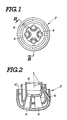
In the drawings: - Fig. l is a bottom view of the first embodiment of a lance for blow-refinement according to the invention;
- Fig. 2 is a sectional view taken along line II - II of Fig. l;
- Fig. 3 is an enlarged section through an auxiliary nozzle in the first embodiment of the lance of Fig. 2;
- Fig. 4 is a sectional view through the second embodiment of an auxiliary nozzle employed in the preferred embodiment of the lance according to the invention;
- Fig. 5 is a sectional view through the auxiliary nozzle to be employed in the third embodiment of the lance according to the invention;
- Fig. 6 is a section taken along line VI - VI of Fig. 5;
- Figs. 7(A) to 7(E) are sections through the auxiliary nozzle employed in the fourth embodiment of the lance according to the invention;
- Fig. 8 is a sectional view through a practical example of the fourth embodiment of Fig. 6;
- Fig. 9 is a view taken along the sections taken along the lines IX-IX in Fig. 8;
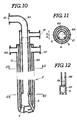
- Fig. l0 is a longitudinal section through the fifth embodiment of a lance for blow-refinement according to the present invention;
- Fig. ll is a section taken along lines XIA-XIA and XIB - XIB of Fig. l0; and
- Fig. l2 is an enlarged section of the encircled area XII of Fig. l0.
- Referring now to the drawings, particularly to Figs. l to 3, the first embodiment of a
lance 2 for blow-refinement in a converter, according to the present invention, has a plurality ofprimary nozzles 4 and a plurality ofauxiliary nozzles 6. In practice, there will be 3 to 5 of the primary andauxiliary nozzles auxiliary nozzles lance 2. Each of the primary andauxiliary nozzles oxygen passage 8 through the axis of thelance 2. Essentially annular cooling medium passages l0 surround theoxygen passage 8 and the primary and theauxiliary nozzles - The
oxygen passage 8 is connected to an oxygen source (not shown) in a per se well-known manner. Therefore, high-purity and high-pressure of oxygen (O₂) is supplied through theoxygen passage 8. In practice, the pressure of the oxygen within theoxygen passage 8 is several kg/cm² to several tens of kg/cm². On the other hand, the cooling medium passages l0 are connected to a cooling medium source (not shown) to conduct a cooling medium, such as coolant, cooling water or the like. - Each
primary nozzle 4 is in the form of a Laval nozzle and has an inner or lower end located near the central axis of the lance and directed toward the upper surface of a molten metal bath in the converter. Theprimary nozzles 4 thus direct oxygen lets toward the upper surface of the molten metal bath, which oxygen jets discharged through the primary nozzles will be hereafter referred to as "primary oxygen jets" or "primary jets". The configuration of theprimary nozzles 4 is determined so that the velocity of the primary oxygen jets discharged or injected therethrough will be supersonic. The high velocity and resulting high kinetic energy of the primary oxygen jets causes strong churning in the molten metal bath and an accordingly rapid reaction. This reaction generates carbon monoxide, which becomes available for secondary combustion. - On the other hand, the inner or lower ends of the
auxiliary nozzles 6 open onto the sides of thelance 2 rather than on its lower face. The inner ends of theauxiliary nozzles 6 are thus located further from the molten bath than the inner ends of theprimary nozzles 4. Theauxiliary nozzles 6 are so arranged and configured to discharge oxygen at a velocity lower than the speed of sound, preferable lower than l00 m/sec. The oxygen jets formed by theauxiliary nozzles 6 will be hereafter referred to as "auxiliary oxygen jets" or "auxiliary jets". When the inner ends of theauxiliary nozzles 6 lie l.5 to 4.0m distance from the upper surface of the molten metal bath, the velocity of the auxiliary oxygen jets discharged through theauxiliary nozzles 6 must be adjusted so as to induce flame propagation at distances of l.0 to 4.0m from the inner ends of theauxiliary nozzles 6. - According to the first embodiment of the
lance 2 according to the present invention, theauxiliary nozzles 6 gradually increase in internal diameter toward their inner ends, as shown in Fig. 3. In this configuration, the velocity of the oxygen jet at the outer end of theauxiliary nozzle 6 is about the speed of sound due to the high pressure, i.e. several kg/cm² to several tens of kg/cm² and the high velocity, i.e. about 200 m/sec. to 300 m/sec, in theoxygen passage 8. The gradual expansion of the internal diameter of theauxiliary passage 8 lowers both the pressure of the oxygen in theauxiliary nozzle 6 and the velocity of the discharged oxygen jet. By adjusting the rate of the expansion of the internal diameter between the outer and inner ends, the velocity of the auxiliary oxygen jet can be adjusted to below the speed of sound. - A similar deceleration of the auxiliary oxygen jet can be obtained by various configurations of the
auxiliary nozzles 6. - For instance, in the second embodiment of the
auxiliary nozzle 6 of Fig. 4, the auxiliary nozzle hassections diameter section 6a adjoins the outer end and has a diameter d₁. On the other hand,the larger-diameter section 6b is located downstream of the smaller-diameter section 6a and adjoins the inner end. The diameter d₂ of the larger-diameter section 6b is significantly greater than that of the smaller- diameter section. In the preferred embodiment, the ratio of the diameters d₁ and d₂ is in the range of d₂/d₁ = l.l to 7.0 Furthermore, the length C of thelarger diameter section 6b should fall in the range d₂ < C < 200d₂ based on empirical observations. - On the other hand, in the third embodiment of Fig. 5, the
auxiliary nozzle 6 increases in internal diameter gradually toward the inner end. Theauxiliary nozzle 6 of Fig. 5 also has a fixed-diameter section 6c separating tapering upper andlower sections diameter section 6c. The conduit assembly l2 comprises a plurality of a small-diameter or capillary conduits l2a, as shown in Fig. 6. These small-diameter conduits l2a exert resistance against the oxygen flow through theauxiliary nozzle 6 and so lowers the velocity of the oxygen to below the speed of sound. This conduit assembly l2 thus augments the effect of the taper of theauxiliary nozzle 6 which gradually increases in diameter toward the inner end in thesections - A similar effect can be achieved by the fourth embodiment of the
auxiliary nozzle 6 of Figs. 7(A) to 7(E). In this fourth embodiment, a plurality of flow-restricting vanes l4 extend inward from the inner periphery of the fixed-diameter section 6c of theauxiliary nozzle 6. The flow-restricting vanes l4 lie perpendicular to the longitudinal axis of the auxiliary nozzle. Each vane l4 occludes the center of theauxiliary nozzle 6, leaving a peripheral section open for oxygen flow. The vanes l4 are arranged so that they overlap as viewed along the axis of theauxiliary nozzle 6. Therefore, a zig-zag path is defined through the fixed-diameter section 6c of theauxiliary passage 6. This further slows down the oxygen flow. Figs. 8 and 9 show a practical application of theauxiliary nozzle 6 of the fourth embodiment of Figs. 7(A) to 7(E). As shown in Fig. 9, threeauxiliary nozzles 6 are arranged in thelance 2 at regular angular intervals, i.e. l20°. Similarly, threeprimary nozzles 4 are arranged radially symmetrically between pairs ofauxiliary nozzles 6. - The
auxiliary nozzles 6 turn at the point where the outer (upper)section 6d and the fixed-diameter section 6c meet. The axis of thesection 6d is essentially parallel to the axis of thelance 2 and the axis of theconstant diameter section 6c lies oblique to the axis of the lance. The angle of the axis of the fixed-diameter section 6c is determined so as to have the inner end of theauxiliary nozzle 6 open at the edge of the lower face of the lance. The inner diameter d₁ at the upper end and the diameter d₂ of the fixed-diameter section are so proportioned that d₂/d₁ = l.8. Similarly, the inner diameter d₃ at the lower end of theauxiliary nozzle 6 and the diameter d₂ of the fixed-diameter section satisfy the expression d₃/d₂ = 2.4. The overall length λ of theauxiliary nozzle 6 is selected to be 20d₁. - Experiments were performed with this
auxiliary nozzle 6. The pressure in theoxygen passage 8 was held at 9.5 kg/cm², which resulted in an auxiliary oxygen jet velocity at the lower end of theauxiliary nozzle 6 of about 70 m/sec. - The velocity of the primary flow at the lower end of the
primary nozzle 4 should still be higher than the speed of sound in order to maintain the effect of churning and rapid reaction. At the same time, effective secondary combustion can be achieved by the relatively low-speed auxiliary oxygen jet through theauxiliary nozzles 6. - Experiments have shown that the rate of combustion of the carbon monoxide gas is determined by its the flame propagation speed. The flame propagation speed of carbon monoxide is lower than or equal to l0 m/sec, most commonly several m/sec. Therefore, in order to achieve effective combustion, the velocity of the auxiliary oxygen jet must be lower than or equal to l0 m/sec at the point where the oxygen mixes with the carbon monoxide. Other experiments have shown that it is preferable to define a combustion zone in the region above the molten metal bath in the converter, where a large amount of foaming slag exists. Toward this end, when the lower or inner end of the
lance 2 is at a point l.5m to 4.0m above the surface of the molten metal bath, the velocity of the auxiliary oxygen jet in the region l.0m to 4.0m from the inner end of the lance will be approximately equal to the flame propagation speed. To obtain this flow velocity, the output velocity of theauxiliary nozzle 6 must be lower than the speed of sound, preferable lower than l00 m/sec. - Therefore, by adjusting the discharge velocity of the auxiliary oxygen jet at the inner end of the
auxiliary nozzle 6 to a velocity of 70 m/sec, effective combustion of the carbon monoxide can be obtained. - On the other hand, experiments have also shown found that heat transmission by the molten metal takes place both by conduction and by radiation. Conductive heating is mediated by the foaming slag which is directly exposed to combustion of carbon monoxide and so accumulates the heat of combustion. When the heated foaming slag returns to the subsurface molten metal bath, it heats the molten metal in the bath. On the other hand, radiative heating is performed directly by the molten metal in the bath. Furthermore, carbon monoxide combustion heats the peripheral walls of the converter. This radiated heat is thus transmitted to the molten metal through the peripheral walls of the converter by conduction.
- In an example, blow-refinement was performed in a 200 t/ch converter. Oxygen is introduced not only from the top of the converter but also from below. Oxygen flows at 500N m³/min through the
primary nozzles 4 and at l70N m³/min through the auxiliary nozzles. The lower face of thelance 2 is set 3.5m above the surface of the molten metal bath. By adjusting the velocity of the auxiliary oxygen jet through theauxiliary nozzle 6, the combustion rate of carbon monoxide can be brought to 35% to 40%. The combustion zone is formed in the region lm to 2m from the inner end of thelance 2. This combustion zone lies about lm to 2m above the molten metal bath. At this distance, the combustion zone could efficiently heat the molten metal. A heating efficiency of 60% to 70% was obtained in this experiment. - Given a high efficiency of combustion of carbon monoxide and a high heating efficiency, the amount of the scrap could be increased to a proportion of 20% relative to other materials. This ratio is about four times as great as in the conventional art.
- Although the foregoing embodiments are directed to auxiliary nozzles connected to a common oxygen passage together with the primary nozzles, it would be possible to connect the auxiliary nozzles to an oxygen passage separate from the oxygen passage for the primary nozzles. Separating the oxygen passages for the primary nozzles and the auxiliary nozzles would facilitate adjustment of the pressure and flow velocity of the oxygen through the auxiliary nozzles.
- Figs. l0, ll and l2 show the fifth embodiment of the lance according to the invention, in which separate
oxygen passages primary nozzles 4 are connected to theprimary oxygen passage 8A and theauxiliary nozzles 6 are connected to theauxiliary oxygen passage 8B. Theauxiliary oxygen passage 8B is annular in cross-section and surrounds theprimary oxygen passage 8A. Theauxiliary oxygen passage 8B itself is surrounded by the cooling medium passages l0. - The
primary oxygen passage 8A is connected to a primary oxygen source (not shown) through an oxygen supply passage which is joined to the outer end l6 thereof. Similarly, theauxiliary oxygen passage 8B is connected to an auxiliary oxygen source (not shown) through an auxiliary oxygen supply passage which is connected to the outer end l8 thereof. Also the cooling medium passage l0 is connected to a cooling medium source (not shown) at theouter end 22 thereof. - The
auxiliary nozzles 6 are all connected to theauxiliary oxygen passage 8B through small-diameter orifices 6f. Theorifice 6f has a diameter d₄ substantially smaller than the inner diameter d₂ of the essentially fixed-diameterauxiliary nozzles 6. - In practice, the inner diameter D₁ of the
primary oxygen passage 8A and the inner diameter D₂ of the auxiliary oxygen passage 8b should exhibit the proportions D₂/D₁ = l.23. On the other hand, the diameter d₄ of theorifice 6f and the inner diameter d₂ of theauxiliary nozzle 6 should exhibit the proportions d₂/d₁ = l.65. The overall length λ of the auxiliary nozzle should be 20d₂. With this construction, the flow velocity of the auxiliary oxygen jet at the inner end of theauxiliary nozzle 6 will be about 95 m/sec it oxygen at a pressure of about l0 kg/cm² is supplied to the auxiliary oxygen passage. Therefore, the auxiliary oxygen jet in the converter will be below the speed of sound and so will generate a flame front near the proper combustion zone. - Therefore, the effects of the former embodiments can be achieved by this embodiment.
- In addition to the effects of the former embodiment, further advantages are obtained by this embodiment. For instance, at the beginning and end of refining operation, when the oxygen pressure in the primary and auxiliary oxygen jets is relatively low, the combustion zone tends to rise toward the lance in the former embodiments. This can be prevented by separating the primary oxygen passage and the auxiliary oxygen passage and by adjusting the timing of the auxiliary oxygen flow.
- Furthermore, separating the primary and auxiliary oxygen passages allows precise oxygen flow control through the auxiliary nozzles according to combustion conditions in the converter. This further improves the efficiency of carbon monoxide combustion and heating of the molten metal.
- While the present invention has been disclosed in terms of the preferred embodiment in order to facilitate better understanding of the invention, it should be appreciated that the invention can be embodied in various ways without departing from the principle of the invention. Therefore, the invention should be understood to include all possible embodiments and modifications to the shown embodiments which can be embodied without departing from the principle of the invention set out in the appended claims.
Claims (13)
a pressurized oxygen source;
a primary nozzle having an outlet directed toward the surface of a molten metal bath in said converter and forming a high-pressure high-velocity primary oxygen let capable of for agitating said molten metal and inducing a chemical reaction therewith;
an auxiliary nozzle for forming an auxiliary oxygen jet for inducing secondary combustion of carbon monoxide generated in the reaction induced by said primary oxygen jet; and
means, incorporated in said auxiliary nozzle, for limiting the velocity of oxygen flow through said auxiliary nozzle to a point where the resulting jet forms a combustion zone in which said carbon monozide oxidizes above said molten metal surface and for adjusting the velocity of said auxiliary oxygen jet within said combustioning zone to approximately the flame propagation speed therein.
Applications Claiming Priority (4)
| Application Number | Priority Date | Filing Date | Title |
|---|---|---|---|
| JP60182487A JPS6244517A (en) | 1985-08-20 | 1985-08-20 | Lance for converter blowing |
| JP182487/85 | 1985-08-20 | ||
| JP3240/86 | 1986-01-10 | ||
| JP61003240A JPS62161911A (en) | 1986-01-10 | 1986-01-10 | Lance for converter blowing |
Publications (2)
| Publication Number | Publication Date |
|---|---|
| EP0214902A1 true EP0214902A1 (en) | 1987-03-18 |
| EP0214902B1 EP0214902B1 (en) | 1990-05-23 |
Family
ID=26336774
Family Applications (1)
| Application Number | Title | Priority Date | Filing Date |
|---|---|---|---|
| EP86401842A Expired - Lifetime EP0214902B1 (en) | 1985-08-20 | 1986-08-19 | Lance for blow-refinement in converter |
Country Status (6)
| Country | Link |
|---|---|
| US (1) | US4746103A (en) |
| EP (1) | EP0214902B1 (en) |
| KR (1) | KR930007311B1 (en) |
| BR (1) | BR8603962A (en) |
| CA (1) | CA1293121C (en) |
| DE (1) | DE3671472D1 (en) |
Cited By (1)
| Publication number | Priority date | Publication date | Assignee | Title |
|---|---|---|---|---|
| US6709630B2 (en) | 2001-12-03 | 2004-03-23 | The BOC Group, plc. | Metallurgical lance and apparatus |
Families Citing this family (12)
| Publication number | Priority date | Publication date | Assignee | Title |
|---|---|---|---|---|
| LU87156A1 (en) * | 1988-03-11 | 1989-10-26 | Arbed | NOZZLE FOR REFINING LANCE |
| LU87855A1 (en) * | 1990-12-10 | 1992-08-25 | Arbed | BLOWING LANCE |
| DE4221266C1 (en) * | 1992-06-26 | 1993-10-21 | Mannesmann Ag | Method and device for inflating oxygen on molten metals |
| US5377960A (en) * | 1993-03-01 | 1995-01-03 | Berry Metal Company | Oxygen/carbon blowing lance assembly |
| US5865876A (en) * | 1995-06-07 | 1999-02-02 | Ltv Steel Company, Inc. | Multipurpose lance |
| DE19529932C1 (en) * | 1995-08-02 | 1997-01-16 | Mannesmann Ag | Lance head of a blow lance for the treatment of melts |
| US5681526A (en) * | 1996-04-23 | 1997-10-28 | Usx Corporation | Method and apparatus for post-combustion of gases during the refining of molten metal |
| US5830259A (en) * | 1996-06-25 | 1998-11-03 | Ltv Steel Company, Inc. | Preventing skull accumulation on a steelmaking lance |
| US5810905A (en) * | 1996-10-07 | 1998-09-22 | Cleveland Cliffs Iron Company | Process for making pig iron |
| US5885323A (en) * | 1997-04-25 | 1999-03-23 | Ltv Steel Company, Inc. | Foamy slag process using multi-circuit lance |
| US6805724B2 (en) * | 2000-02-10 | 2004-10-19 | Process Technology International, Inc. | Method for particulate introduction for metal furnaces |
| US6749661B2 (en) * | 2000-02-10 | 2004-06-15 | Process Technology International, Inc. | Method for melting and decarburization of iron carbon melts |
Citations (4)
| Publication number | Priority date | Publication date | Assignee | Title |
|---|---|---|---|---|
| FR1543169A (en) * | 1964-02-06 | 1900-01-01 | Capillary tube nozzle | |
| DE1064970B (en) * | 1955-01-05 | 1959-09-10 | Hoerder Huettenunion Ag | Process for overwind refining of phosphorus-containing pig iron |
| FR1346214A (en) * | 1963-02-02 | 1963-12-13 | Demag Ag | Lance for blowing oxygen especially in steel refining furnaces or converters |
| GB1190137A (en) * | 1968-07-02 | 1970-04-29 | Inst Chernoi Metallurgii | Apparatus for Blowing Gas Through Molten Metal |
Family Cites Families (4)
| Publication number | Priority date | Publication date | Assignee | Title |
|---|---|---|---|---|
| US3745943A (en) * | 1972-03-31 | 1973-07-17 | Bethlehem Steel Corp | Baffle nose tuyere |
| SU438702A1 (en) * | 1972-04-10 | 1974-08-05 | Центральный научно-исследовательский институт черной металлургии им. И.П. Бардина | Lance for purging liquid metal |
| JPS5310225A (en) * | 1976-07-16 | 1978-01-30 | Matsushita Electric Ind Co Ltd | Recorder |
| DE3231867A1 (en) * | 1982-08-27 | 1984-03-01 | Saar-Metallwerke GmbH, 6600 Saarbrücken | DUAL CIRCUIT FOR FRESH METAL MELTING |
-
1986
- 1986-08-18 CA CA000516195A patent/CA1293121C/en not_active Expired - Lifetime
- 1986-08-18 US US06/897,524 patent/US4746103A/en not_active Expired - Fee Related
- 1986-08-19 EP EP86401842A patent/EP0214902B1/en not_active Expired - Lifetime
- 1986-08-19 DE DE8686401842T patent/DE3671472D1/en not_active Expired - Fee Related
- 1986-08-19 BR BR8603962A patent/BR8603962A/en not_active IP Right Cessation
- 1986-08-19 KR KR1019860006818A patent/KR930007311B1/en not_active Expired - Fee Related
Patent Citations (4)
| Publication number | Priority date | Publication date | Assignee | Title |
|---|---|---|---|---|
| DE1064970B (en) * | 1955-01-05 | 1959-09-10 | Hoerder Huettenunion Ag | Process for overwind refining of phosphorus-containing pig iron |
| FR1346214A (en) * | 1963-02-02 | 1963-12-13 | Demag Ag | Lance for blowing oxygen especially in steel refining furnaces or converters |
| FR1543169A (en) * | 1964-02-06 | 1900-01-01 | Capillary tube nozzle | |
| GB1190137A (en) * | 1968-07-02 | 1970-04-29 | Inst Chernoi Metallurgii | Apparatus for Blowing Gas Through Molten Metal |
Non-Patent Citations (1)
| Title |
|---|
| PATENTS ABSTRACTS OF JAPAN, vol. 2, no. 122, 13th October 1978, page 2946 C 78; & JP-A-53 102 205 (NIPPON KOKAN K.K.) (Cat. A,D) 06-09-1978 * |
Cited By (1)
| Publication number | Priority date | Publication date | Assignee | Title |
|---|---|---|---|---|
| US6709630B2 (en) | 2001-12-03 | 2004-03-23 | The BOC Group, plc. | Metallurgical lance and apparatus |
Also Published As
| Publication number | Publication date |
|---|---|
| DE3671472D1 (en) | 1990-06-28 |
| KR870002277A (en) | 1987-03-30 |
| KR930007311B1 (en) | 1993-08-05 |
| BR8603962A (en) | 1987-03-31 |
| EP0214902B1 (en) | 1990-05-23 |
| CA1293121C (en) | 1991-12-17 |
| US4746103A (en) | 1988-05-24 |
Similar Documents
| Publication | Publication Date | Title |
|---|---|---|
| EP0214902B1 (en) | Lance for blow-refinement in converter | |
| KR930004731B1 (en) | Post-combustion Method and Apparatus for Reaction Gas in Melting Bath | |
| US5802097A (en) | Melting method for an electric ARC furnace with alternative sources of energy and relative electric ARC furnace with special burner positioning | |
| US2829960A (en) | Method and metallurgical device for the refining of steel | |
| US4541617A (en) | Lance structure for oxygen-blowing process in top-blown converters | |
| CA2483131C (en) | Lance for injecting particulate material into liquid metal | |
| EP1497472B1 (en) | Injection of solids into liquids by means of a shrouded supersonic gas jet | |
| EP0832305B1 (en) | Combined oxygen blowing/fuel burner lance assembly | |
| US4366953A (en) | Oxygen lance | |
| US5681526A (en) | Method and apparatus for post-combustion of gases during the refining of molten metal | |
| KR100370632B1 (en) | How to melt metal charges in rotary furnaces and rotary furnaces to carry out these methods | |
| US4422624A (en) | Concentrate burner | |
| US20090229416A1 (en) | Refining Molten Metal | |
| US3259484A (en) | Method and apparatus for producing steel from pig iron | |
| RU2186294C2 (en) | Multi-nozzle end-piece for melting unit | |
| RU1822423C (en) | Open-hearth furnace arch gas-oxygen burner | |
| JPS6244517A (en) | Lance for converter blowing | |
| SU899661A1 (en) | Gas-oxygen tuyere for blasting melts | |
| JPS55164017A (en) | Gas blow-in tuyere for refining | |
| SU753907A1 (en) | Tuyere for bottom blasting of melt | |
| SU1168608A1 (en) | Tuyere | |
| GB1591318A (en) | Injection of combustibles into a blast furnace | |
| WO1997002366A2 (en) | Method and apparatus for after-burning atmospheric gases in a steel smelting arc furnace | |
| CA2225404A1 (en) | Method and apparatus for after-burning the combustible components of the atmosphere in metallurgical smelting vessels | |
| JPS62164813A (en) | Converter lance |
Legal Events
| Date | Code | Title | Description |
|---|---|---|---|
| PUAI | Public reference made under article 153(3) epc to a published international application that has entered the european phase |
Free format text: ORIGINAL CODE: 0009012 |
|
| AK | Designated contracting states |
Kind code of ref document: A1 Designated state(s): DE FR GB |
|
| 17P | Request for examination filed |
Effective date: 19870914 |
|
| 17Q | First examination report despatched |
Effective date: 19890803 |
|
| GRAA | (expected) grant |
Free format text: ORIGINAL CODE: 0009210 |
|
| AK | Designated contracting states |
Kind code of ref document: B1 Designated state(s): DE FR GB |
|
| REF | Corresponds to: |
Ref document number: 3671472 Country of ref document: DE Date of ref document: 19900628 |
|
| ET | Fr: translation filed | ||
| PLBE | No opposition filed within time limit |
Free format text: ORIGINAL CODE: 0009261 |
|
| STAA | Information on the status of an ep patent application or granted ep patent |
Free format text: STATUS: NO OPPOSITION FILED WITHIN TIME LIMIT |
|
| 26N | No opposition filed | ||
| PGFP | Annual fee paid to national office [announced via postgrant information from national office to epo] |
Ref country code: GB Payment date: 19970811 Year of fee payment: 12 Ref country code: FR Payment date: 19970811 Year of fee payment: 12 |
|
| PGFP | Annual fee paid to national office [announced via postgrant information from national office to epo] |
Ref country code: DE Payment date: 19970822 Year of fee payment: 12 |
|
| PG25 | Lapsed in a contracting state [announced via postgrant information from national office to epo] |
Ref country code: GB Free format text: LAPSE BECAUSE OF NON-PAYMENT OF DUE FEES Effective date: 19980819 |
|
| GBPC | Gb: european patent ceased through non-payment of renewal fee |
Effective date: 19980819 |
|
| PG25 | Lapsed in a contracting state [announced via postgrant information from national office to epo] |
Ref country code: FR Free format text: LAPSE BECAUSE OF NON-PAYMENT OF DUE FEES Effective date: 19990430 |
|
| PG25 | Lapsed in a contracting state [announced via postgrant information from national office to epo] |
Ref country code: DE Free format text: LAPSE BECAUSE OF NON-PAYMENT OF DUE FEES Effective date: 19990601 |
|
| REG | Reference to a national code |
Ref country code: FR Ref legal event code: ST |