US5865876A - Multipurpose lance - Google Patents
Multipurpose lance Download PDFInfo
- Publication number
- US5865876A US5865876A US08/767,994 US76799496A US5865876A US 5865876 A US5865876 A US 5865876A US 76799496 A US76799496 A US 76799496A US 5865876 A US5865876 A US 5865876A
- Authority
- US
- United States
- Prior art keywords
- lance
- nozzle
- gas
- furnace
- nozzle opening
- Prior art date
- Legal status (The legal status is an assumption and is not a legal conclusion. Google has not performed a legal analysis and makes no representation as to the accuracy of the status listed.)
- Expired - Lifetime
Links
- 239000007789 gas Substances 0.000 claims abstract description 236
- QVGXLLKOCUKJST-UHFFFAOYSA-N atomic oxygen Chemical compound [O] QVGXLLKOCUKJST-UHFFFAOYSA-N 0.000 claims abstract description 75
- 239000001301 oxygen Substances 0.000 claims abstract description 75
- 229910052760 oxygen Inorganic materials 0.000 claims abstract description 72
- 239000011261 inert gas Substances 0.000 claims abstract description 45
- 238000009628 steelmaking Methods 0.000 claims abstract description 16
- 239000002893 slag Substances 0.000 claims description 80
- 238000007664 blowing Methods 0.000 claims description 31
- 229910001882 dioxygen Inorganic materials 0.000 claims description 24
- 238000004891 communication Methods 0.000 claims description 23
- 210000003625 skull Anatomy 0.000 claims description 22
- MYMOFIZGZYHOMD-UHFFFAOYSA-N Dioxygen Chemical compound O=O MYMOFIZGZYHOMD-UHFFFAOYSA-N 0.000 claims description 21
- 238000000034 method Methods 0.000 claims description 20
- 238000004140 cleaning Methods 0.000 claims description 17
- 239000012530 fluid Substances 0.000 claims description 13
- 238000007599 discharging Methods 0.000 claims description 7
- 230000013011 mating Effects 0.000 claims 2
- 239000002826 coolant Substances 0.000 description 54
- IJGRMHOSHXDMSA-UHFFFAOYSA-N Atomic nitrogen Chemical compound N#N IJGRMHOSHXDMSA-UHFFFAOYSA-N 0.000 description 36
- 238000007670 refining Methods 0.000 description 35
- 229910001873 dinitrogen Inorganic materials 0.000 description 22
- 239000002184 metal Substances 0.000 description 20
- 229910052751 metal Inorganic materials 0.000 description 20
- XLYOFNOQVPJJNP-UHFFFAOYSA-N water Substances O XLYOFNOQVPJJNP-UHFFFAOYSA-N 0.000 description 12
- 229910000831 Steel Inorganic materials 0.000 description 11
- 239000010959 steel Substances 0.000 description 11
- 238000013461 design Methods 0.000 description 9
- 230000000712 assembly Effects 0.000 description 8
- 238000000429 assembly Methods 0.000 description 8
- 238000002485 combustion reaction Methods 0.000 description 8
- 239000000155 melt Substances 0.000 description 7
- 229910052757 nitrogen Inorganic materials 0.000 description 7
- 238000003780 insertion Methods 0.000 description 5
- 230000037431 insertion Effects 0.000 description 5
- 230000008878 coupling Effects 0.000 description 4
- 238000010168 coupling process Methods 0.000 description 4
- 238000005859 coupling reaction Methods 0.000 description 4
- 238000010276 construction Methods 0.000 description 3
- 238000012423 maintenance Methods 0.000 description 3
- 239000000463 material Substances 0.000 description 3
- XEEYBQQBJWHFJM-UHFFFAOYSA-N Iron Chemical compound [Fe] XEEYBQQBJWHFJM-UHFFFAOYSA-N 0.000 description 2
- VYPSYNLAJGMNEJ-UHFFFAOYSA-N Silicium dioxide Chemical compound O=[Si]=O VYPSYNLAJGMNEJ-UHFFFAOYSA-N 0.000 description 2
- 238000011109 contamination Methods 0.000 description 2
- 230000000694 effects Effects 0.000 description 2
- 238000012545 processing Methods 0.000 description 2
- 238000010926 purge Methods 0.000 description 2
- 230000001105 regulatory effect Effects 0.000 description 2
- 238000010079 rubber tapping Methods 0.000 description 2
- 238000000926 separation method Methods 0.000 description 2
- 239000000654 additive Substances 0.000 description 1
- 238000013019 agitation Methods 0.000 description 1
- 230000015572 biosynthetic process Effects 0.000 description 1
- YLUIKWVQCKSMCF-UHFFFAOYSA-N calcium;magnesium;oxygen(2-) Chemical compound [O-2].[O-2].[Mg+2].[Ca+2] YLUIKWVQCKSMCF-UHFFFAOYSA-N 0.000 description 1
- 229910052681 coesite Inorganic materials 0.000 description 1
- 230000001143 conditioned effect Effects 0.000 description 1
- 229910052906 cristobalite Inorganic materials 0.000 description 1
- 230000003247 decreasing effect Effects 0.000 description 1
- 230000006866 deterioration Effects 0.000 description 1
- 230000004907 flux Effects 0.000 description 1
- 230000008014 freezing Effects 0.000 description 1
- 238000007710 freezing Methods 0.000 description 1
- CNKHSLKYRMDDNQ-UHFFFAOYSA-N halofenozide Chemical compound C=1C=CC=CC=1C(=O)N(C(C)(C)C)NC(=O)C1=CC=C(Cl)C=C1 CNKHSLKYRMDDNQ-UHFFFAOYSA-N 0.000 description 1
- 229910052742 iron Inorganic materials 0.000 description 1
- 238000002955 isolation Methods 0.000 description 1
- 238000004519 manufacturing process Methods 0.000 description 1
- 239000000203 mixture Substances 0.000 description 1
- QJGQUHMNIGDVPM-UHFFFAOYSA-N nitrogen(.) Chemical compound [N] QJGQUHMNIGDVPM-UHFFFAOYSA-N 0.000 description 1
- 239000002245 particle Substances 0.000 description 1
- 238000002360 preparation method Methods 0.000 description 1
- 230000003134 recirculating effect Effects 0.000 description 1
- 239000011819 refractory material Substances 0.000 description 1
- 238000007789 sealing Methods 0.000 description 1
- 239000000377 silicon dioxide Substances 0.000 description 1
- 229910052682 stishovite Inorganic materials 0.000 description 1
- 229910052905 tridymite Inorganic materials 0.000 description 1
Images
Classifications
-
- F—MECHANICAL ENGINEERING; LIGHTING; HEATING; WEAPONS; BLASTING
- F27—FURNACES; KILNS; OVENS; RETORTS
- F27D—DETAILS OR ACCESSORIES OF FURNACES, KILNS, OVENS, OR RETORTS, IN SO FAR AS THEY ARE OF KINDS OCCURRING IN MORE THAN ONE KIND OF FURNACE
- F27D25/00—Devices or methods for removing incrustations, e.g. slag, metal deposits, dust; Devices or methods for preventing the adherence of slag
- F27D25/008—Devices or methods for removing incrustations, e.g. slag, metal deposits, dust; Devices or methods for preventing the adherence of slag using fluids or gases, e.g. blowers, suction units
-
- C—CHEMISTRY; METALLURGY
- C22—METALLURGY; FERROUS OR NON-FERROUS ALLOYS; TREATMENT OF ALLOYS OR NON-FERROUS METALS
- C22B—PRODUCTION AND REFINING OF METALS; PRETREATMENT OF RAW MATERIALS
- C22B15/00—Obtaining copper
-
- C—CHEMISTRY; METALLURGY
- C21—METALLURGY OF IRON
- C21C—PROCESSING OF PIG-IRON, e.g. REFINING, MANUFACTURE OF WROUGHT-IRON OR STEEL; TREATMENT IN MOLTEN STATE OF FERROUS ALLOYS
- C21C5/00—Manufacture of carbon-steel, e.g. plain mild steel, medium carbon steel or cast steel or stainless steel
- C21C5/28—Manufacture of steel in the converter
- C21C5/42—Constructional features of converters
- C21C5/46—Details or accessories
- C21C5/4606—Lances or injectors
-
- C—CHEMISTRY; METALLURGY
- C21—METALLURGY OF IRON
- C21C—PROCESSING OF PIG-IRON, e.g. REFINING, MANUFACTURE OF WROUGHT-IRON OR STEEL; TREATMENT IN MOLTEN STATE OF FERROUS ALLOYS
- C21C5/00—Manufacture of carbon-steel, e.g. plain mild steel, medium carbon steel or cast steel or stainless steel
- C21C5/28—Manufacture of steel in the converter
- C21C5/42—Constructional features of converters
- C21C5/46—Details or accessories
- C21C5/4693—Skull removal; Cleaning of the converter mouth
-
- F—MECHANICAL ENGINEERING; LIGHTING; HEATING; WEAPONS; BLASTING
- F27—FURNACES; KILNS; OVENS; RETORTS
- F27D—DETAILS OR ACCESSORIES OF FURNACES, KILNS, OVENS, OR RETORTS, IN SO FAR AS THEY ARE OF KINDS OCCURRING IN MORE THAN ONE KIND OF FURNACE
- F27D3/00—Charging; Discharging; Manipulation of charge
- F27D3/16—Introducing a fluid jet or current into the charge
- F27D2003/162—Introducing a fluid jet or current into the charge the fluid being an oxidant or a fuel
- F27D2003/163—Introducing a fluid jet or current into the charge the fluid being an oxidant or a fuel the fluid being an oxidant
- F27D2003/164—Oxygen
-
- F—MECHANICAL ENGINEERING; LIGHTING; HEATING; WEAPONS; BLASTING
- F27—FURNACES; KILNS; OVENS; RETORTS
- F27D—DETAILS OR ACCESSORIES OF FURNACES, KILNS, OVENS, OR RETORTS, IN SO FAR AS THEY ARE OF KINDS OCCURRING IN MORE THAN ONE KIND OF FURNACE
- F27D3/00—Charging; Discharging; Manipulation of charge
- F27D3/16—Introducing a fluid jet or current into the charge
- F27D2003/168—Introducing a fluid jet or current into the charge through a lance
- F27D2003/169—Construction of the lance, e.g. lances for injecting particles
Definitions
- the present invention relates to cleaning and maintaining a steelmaking furnace and, in particular, to a multipurpose lance assembly and gas flow control apparatus for cleaning and maintaining a basic oxygen furnace.
- a basic oxygen furnace (hereinafter "BOF") used to make steel includes an outer steel shell and a refractory lining inside the outer steel shell.
- Most basic oxygen furnaces are equipped with two lances, only one of which can be in an operative position above the furnace at a given time.
- One of the two lances is an idle side auxiliary lance that is kept on standby outside the perimeter of the furnace.
- the other lance is a main oxygen blowing refining lance which, during the steelmaking process, is located in the furnace above the bath.
- a motorized lance transport and elevator system is used to manipulate the main and auxiliary lances.
- skull a material commonly known as skull, a mixture of molten metal and oxides, is deposited on the working surface of the furnace and on the lances.
- skull a material commonly known as skull, a mixture of molten metal and oxides.
- the formation of skull at the cone of the BOF is undesirable because it restricts the ability to lower lances and charge scrap into the cone of the furnace.
- Oxygen gas is blown from the deskulling lance to melt the skull at the furnace cone by moving the lance vertically up and down near the location of the skull.
- slag splashing In which a lance is used to blow an inert gas toward the slag layer. This causes the slag to be splashed upwardly onto the refractory walls and to coat portions of the refractory walls that have been worn. The slag cools on the refractory walls, effectively repairing worn portions of the walls.
- the slag splashing process may increase the problem of skull build-up at the cone of the furnace.
- some BOF shops employ an idle-side deskulling lance and a refining lance.
- the deskulling lance is used to melt the skull from the furnace cone and the refining lance is used for refining the molten metal and for the slag splashing operation.
- This selection of lances is undesirable.
- the slag splashing tends to coat the refining lance with skull which requires removing the lance from the furnace. Thus, the furnace must be shut down frequently to replace the skulled refining lance.
- the present invention relates to a slag splashing operation for maintaining a steelmaking furnace and a deskulling operation for cleaning the furnace, as well as a single lance apparatus capable of carrying out both operations.
- the present invention avoids the problems of conventional two lance carriage BOF shops.
- the equipment for carrying out the method of the present invention preferably includes an auxiliary idle side lance used in a two lance carriage BOF shop.
- the BOF shop also employs a typical oxygen blowing refining lance.
- a first embodiment of the present invention is a "double circuit" lance assembly, which is defined herein as having two separate gas flow passageways isolated from mutual fluid communication that each lead to separate nozzles.
- This embodiment of the lance has one passageway leading to main nozzles and another passageway leading to auxiliary nozzles, both of which are disposed in the tip.
- the lance apparatus includes an array of control valves which are connectable to existing oxygen and nitrogen supply lines in a BOF shop and communicate with the lance passageways. Under regulation of the control valves, various combinations of oxygen and nitrogen gas may be selectively supplied to the main and auxiliary nozzles to conduct slag splashing and deskulling, as well as refining with post combustion capabilities in the event of an emergency.
- selective discharge means may be used for enabling an oxygen-containing gas and an inert gas to be selectively discharged from at least one main nozzle and auxiliary nozzle.
- the selective discharge means comprises a first inlet communicable with a first gas supply, a second inlet communicable with a second gas supply, a first outlet operatively connected to the main gas flow passage and a second outlet operatively connected to the auxiliary gas flow passage.
- a valve means selectively communicates the first and second inlets with the first and second outlets.
- valve means comprises an array of two-position valves including a first valve connected to the first inlet and the first outlet.
- a second valve is connected to the first inlet and the second outlet.
- a third valve is connected to the second inlet and the first outlet.
- a fourth valve is connected to the second inlet and the second outlet.
- An apparatus for selectively opening and closing each of the first, second, third and fourth valves may also be provided.
- a second preferred embodiment of the present invention is directed to a "single circuit" lance assembly which is connectable to oxygen and nitrogen supply lines of the BOF shop.
- a "single circuit" lance is one in which a single common gas flow passageway leads to all of the nozzles of the lance.
- the common gas flow passageway terminates in one or more main nozzles provided at the lower end portion of the lance and one or more auxiliary nozzles spaced upwardly from the lower end portion of the lance.
- Gas supply means selectively introduces different gases into the passageway.
- the lance apparatus can be operated to emit either an oxygen-containing gas or an inert gas from the first and second nozzle openings at the same time.
- the lance body extends along a longitudinal axis and each second nozzle extends along a gas flow path with respect to the longitudinal axis in the range of from about 60° to about 75°.
- the angles of the first main nozzles may be adjusted as desired by using nozzle extensions.
- Each nozzle extension is preferably independently adjustable to project from its respective nozzle at one or more angles.
- Each first nozzle extends along a gas flow path at an angle with respect to the longitudinal axis in the range of from about 5° to about 20°.
- the nozzle extensions enable gas to be blown from the first nozzles at ranges of angles selected from the group consisting of: a) about 10° to about 20°, b) about 8° to about 15° and c) about 10° to about 14°.
- each plug member is provided for preventing the flow of gas through the first nozzle opening.
- a portion of each first nozzle opening is defined by an interior threaded surface.
- Each of the plug members has an exterior threaded surface for engaging one of the interior threaded surfaces.
- each nozzle extension has an exterior threaded surface for engaging one of the interior threaded surfaces. The plugs and nozzle extensions may also be fastened to the lance using a latch device.
- a third, preferred embodiment of the invention is directed to a double circuit lance assembly having main nozzles disposed at the lower end portion of the lance and auxiliary nozzles disposed at a location spaced upwardly from the lower end portion.
- One gas flow passageway leads to the main nozzles and another gas flow passageway leads to the auxiliary nozzles. These gas flow passageways are isolated from mutual fluid communication. Accordingly, the lance can blow an oxygen-containing gas and an inert gas from both the main and auxiliary nozzles to conduct slag splashing and deskulling.
- One aspect of the third double circuit lance embodiment includes an elongated lance body having at least one first nozzle opening proximal to an end that extends into the furnace and at least one other second nozzle opening spaced upwardly from the first nozzle opening.
- a structure defines a first main gas flow passageway and a second auxiliary gas flow passageway extending through the body to the first nozzle opening and the second nozzle opening, respectively.
- the passageways are isolated from mutual fluid communication.
- a gas supply means selectively introduces different gases into the passageways.
- the lance apparatus can be operated to emit either different gases or the same gas from the first and second nozzle openings at the same time.
- the gases comprise inert and oxygen-containing gases.
- the gas supply means comprises first valve means connected to an oxygen-containing gas source and to the first and second passageways.
- the first valve means is operable in one position to connect the oxygen gas source to both passageways and in another position to connect the oxygen gas source to a selected one of the passageways.
- a second valve means is connected to an gas source comprising an inert gas. The second valve means is operable in one position to connect the inert gas source to both passageways and in another position to connect the inert gas source to a selected one of the passageways.
- One preferred aspect of the second and third embodiments of the invention is directed to a lance apparatus including an elongated lance body comprising a barrel and a tip portion disposed at a lower end of the barrel that extends into the furnace. At least one first nozzle opening is disposed in the tip portion and at least one other second nozzle opening is disposed in the barrel at a location spaced upwardly from the first nozzle opening.
- a structure defines at least one passageway extending through the body to the first nozzle opening and the second nozzle opening.
- Gas supply means selectively introduces different gases into the passageways.
- the lance apparatus can be operated to emit either different gases or the same gas from the first and second nozzle openings at the same time.
- the gases include inert and oxygen-containing gases.
- lance assemblies of the present invention do not suffer from significant skulling. Lance skulling is avoided by the present invention because a conventional lance is used for refining and the lance of the invention is used for furnace cleaning/maintenance. Conventionally, such as when one lance is used for both refining and slag splashing, the lance suffers from skulling since it is used frequently and not allowed to cool. Since the lance of the invention is not ordinarily used for refining, "self-cleaning" of the lance occurs when it is allowed to cool.
- the refining lance since the refining lance is not required to be used for slag splashing in a BOF shop employing the invention, the refining lance does not suffer from excessive skulling. Therefore, furnace down time is minimized, because there is no need to replace skulled lances or to exchange a dedicated idle-side deskulling lance with a dedicated idle-side slag splashing lance.
- Another advantage is that in the deskulling operation using the single circuit design, oxygen gas is only blown through the auxiliary nozzles, the main nozzles being plugged. During deskulling with the double circuit lance design, oxygen gas is blown from the auxiliary nozzles and an inert gas is blown from the main nozzles. Thus, in both the single and double circuit lance designs, due to blowing inert gas or plugging the main nozzles, the main nozzles are not clogged with skull and the furnace walls are not damaged.
- an inert gas flows through both the main and auxiliary nozzles.
- the inert gas flowing through the auxiliary nozzles prevents them from becoming clogged with skull, while the inert gas flowing through the main nozzles effects the slag splashing operation.
- the angles of the main and auxiliary nozzles may be adjusted as desired to suit the combined slag splashing and deskulling operations.
- One aspect of a method of operating a lance in a basic oxygen furnace includes moving the lance into the furnace along an axis of travel.
- Gas such as an inert gas is blown from the lance in a direction forming an angle of about 5° to about 20° with respect to the axis of travel. This gas is preferably blown from a lower end portion of the lance.
- Gas such as an oxygen-containing gas is blown from the lance in a direction forming an angle of from about 60° to about 75° with respect to the axis of travel. This gas is preferably blown from a location spaced upwardly from the lower end portion of the lance.
- Another aspect of the method includes moving a lance along an axis of travel into the basic oxygen furnace until the end of the lance is positioned a desired distance from the bottom of the basic oxygen furnace.
- a gas comprising inert gas is blown onto slag so as to deposit the slag onto the walls of the basic oxygen furnace.
- This blowing step is carried out by discharging the inert gas from preferably the lower end portion of the lance along a flow path which forms an angle from about 5° to about 20° with respect to the axis of travel.
- an inert gas is preferably also blown from the second nozzles in both the single and double circuit lances.
- the basic oxygen furnace is deskulled by blowing an oxygen-containing gas from preferably above the lower end portion of the lance onto skull deposits on the walls of the basic oxygen furnace.
- the deskulling step is carried out by discharging the oxygen-containing gas from the lance along a flow path which forms an angle of about 60° to about 75° with respect to the axis of travel.
- an inert gas is preferably blown from each first nozzle during deskulling.
- oxygen gas is prevented from flowing from each first nozzle during deskulling by inserting a plug member in each first nozzle.
- FIG. 1A is an elevational schematic view of a portion of a conventional BOF shop
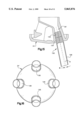
- FIG. 1B is a diagrammatic top plan view of a portion of the lance transport and elevator system of the BOF shop of FIG. 1A;
- FIG. 2 is a side elevational view of a first embodiment of a lance constructed in accordance with the present invention in the form of a double circuit lance;
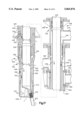
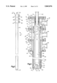
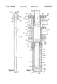
- FIG. 3 is an enlarged, vertical cross-sectional view of the lance shown in FIG. 2;
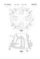
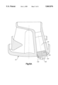
- FIG. 4 is an enlarged end view of a lance tip constructed in accordance with the present invention.
- FIG. 5 is an elevational cross-sectional view of the tip of FIG. 4 taken along lines V--V thereof;
- FIG. 6 is a schematic view of a lance control valve array of the present invention.
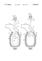
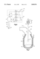
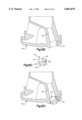
- FIG. 7 is a side elevational view depicting the first embodiment of the lance during oxygen blowing (refining);
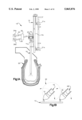
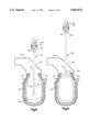
- FIG. 8 is a view depicting the first embodiment of the lance during slag splashing
- FIG. 9 is a view depicting the first embodiment of the lance during deskulling
- FIG. 10 is a side elevational view of a second preferred embodiment of a lance constructed in accordance with the present invention in the form of a single circuit lance;
- FIG. 11 is an enlarged, vertical cross-sectional view of the lance assembly shown in FIG. 10;
- FIG. 12A is an enlarged elevational cross-sectional view of a tip of the lance of the second embodiment showing a threaded plug obstructing a main nozzle of the tip;
- FIG. 12B is an enlarged elevational cross-sectional view of another tip of the lance of the second embodiment
- FIG. 12C is an enlarged elevational view of a removable plug for selectively obstructing a main nozzle of the tip of FIG. 12B;
- FIG. 12D is an enlarged, elevational, partial cross-sectional view of the removable plug obstructing a main nozzle of the tip;
- FIG. 13 is a view depicting the lance of the second embodiment during slag splashing
- FIG. 14 is a view depicting the lance of the second embodiment during deskulling
- FIG. 15 is an elevational cross-sectional view of a nozzle extension inserted into a main nozzle of a tip
- FIG. 16 is a bottom plan view of the tip of FIG. 16.
- FIG. 17 is a vertical cross-sectional view of a third embodiment of the lance of the present invention in the form of a double circuit lance.
- the lance includes an elongated barrel 30 having an upper end portion connected to a housing 32 and a lower end portion at which a tip 34 is disposed.
- the lance includes main nozzles 36 and auxiliary nozzles 38 which, in this particular embodiment, are disposed in the tip.
- the main and auxiliary nozzles are both capable of blowing either an inert gas or an oxygen-containing gas.
- FIG. 1A shows a BOF steelmaking shop, generally designated by reference numeral 10.
- the shop comprises a lance transport and elevator system 12 having a first lance carriage 14 and a second lance carriage 18.
- the first lance carriage 14 supports a first lance 16 used for refining.
- the second lance carriage 18 supports a second auxiliary lance of the present invention, for example the lance 28, which is used for both deskulling and slag splashing.
- the lance carriages are pivoted in a conventional manner between alternate "operating" and "standby" positions with respect to the top of a BOF vessel 22.
- the lance transport and elevator system 12 includes winch and cable means (shown in phantom lines in FIG. 1A), which move each of the lance carriages 14 and 18 to lower and raise the lances into and from the BOF.
- the lance gas inlet 23 of the appropriate one of the lances may be connected via a diverter valve 25 or similar gas flow control means to gas supply lines 24, 26.
- the gas supply lines 24, 26 are respectively connected to sources 24a, 26a of a pressurized oxygen-containing gas and a pressurized inert gas such as nitrogen gas.
- the operating lance is also connected to unillustrated intake and return lines of a conventional recirculating coolant system.
- the housing 32 includes modular housing sections 39, 40 and 41.
- The, housing section 39 includes a metal cylindrical pipe 42 having a pair of annular plates 44 and 46 welded at each end.
- the plates 44 and 46 include a plurality of bolt holes 44a, 46a concentrically arranged about the pipe 42 to connect the housing section 39 to the housing section 40.
- An auxiliary gas inlet pipe 48 is laterally affixed to the wall of the pipe 42.
- the housing section 40 is formed by a metal pipe 52 having a pair of annular plates 54 and 56 welded at each end.
- a water coolant inlet pipe 58 is laterally affixed to the pipe 52.
- the housing section 41 includes a metal pipe 62 having a pair of annular plates 64 and 66 welded at each end.
- the annular plates 54 and 56 of the housing section 40 include a plurality of bolt openings 54a and 56a circumferentially arranged about the pipe 52.
- the annular plates 64 and 66 of the housing section 41 include a plurality of bolt holes 64a, 66a circumferentially arranged about the pipe 62.
- a lateral coolant outlet pipe 68 is affixed to the pipe 62.
- the plate 46 of the housing section 39 is affixed to a pair of annular plates 72 and 74 each having bolt holes 72a and 74a arranged to be in alignment with the bolt holes 46a.
- the annular plates 46, 72 and 74 are connected together using bolt assemblies.
- An annular plate 76 is sandwiched between the plates 44 and 54 and includes a plurality of bolt holes 76a in alignment with the bolt holes 44a and 54a.
- An annular plate 78 is interposed between the annular plates 56 and 64 and includes bolt holes 78a in alignment with the bolt holes 56a and 64a.
- the three plates are connected together using bolt assemblies.
- the annular plate 66 is affixed to an annular plate 82 that is welded to the barrel 30.
- the plate 82 includes concentrically arranged bolt holes 82a disposed in alignment with the bolt holes 66a for receiving bolt assemblies to affix the annular plate 66 to the plate 82.
- the barrel 30 preferably comprises an elongated exterior metal pipe 86 that is welded to an internal edge 88 of the annular plate 82.
- the tip 34 includes at least one of the main nozzles 36 and at least one of the auxiliary nozzles 38.
- nozzle means an opening leading to the exterior of the lance, tubular members inserted into such an opening and tubular members formed integrally with the lance that form such an opening.
- FIGS. 4 and 5 which show the tip of the lance 28, a plurality of main nozzles 36, most preferably four, are circumferentially spaced about a central axis "A" of the lance.
- the main nozzles preferably diverge outwardly from the central axis A at an angle ⁇ ranging from about 5° to about 20°.
- a plurality of the smaller diameter auxiliary nozzles 38 are circumferentially spaced about the central axis A.
- the auxiliary nozzles 38 diverge from the central axis A at an angle ⁇ in the range of from about 30° or greater.
- a centralmost pipe 96 extends substantially the entire length of the lance.
- the upper end of the pipe 96 is disposed adjacent the housing section 39 and its lower end is welded to the tip to define a main gas flow passageway 98 that communicates exclusively with the main nozzles 36.
- the upper end of the pipe 96 is welded to an internal sleeve 100 which is capable of relative movement within an outer sleeve 102.
- the outer sleeve 102 is welded to the annular plate 72.
- a third sleeve 104 is concentrically disposed within the internal sleeve 100.
- the sleeve 104 is welded to the annular plate 74 and extends upwardly therefrom to define a main lance gas inlet pipe 106.
- the sleeve 104 includes an enlarged end portion 104a fitted with at least one O-ring 108 which provides a slip seal between the sleeve 104 and the concentric sleeve 100.
- the sleeve 100 includes an enlarged end portion 100a having at least one O-ring 110 which provides a slip seal between the sleeve 100 and the outer sleeve 102.
- a cylindrical conduit 112 is concentrically mounted about the pipe 96 to form an auxiliary gas flow passage 114 therebetween and extends from a first end 116 longitudinally to the tip where it is welded.
- the auxiliary gas flow passage 114 communicates exclusively with the auxiliary nozzles 38.
- the upper end 116 of the conduit 112 forms a tapered restriction 116a for directing the flow of auxiliary gas into the auxiliary gas flow passage 114.
- the upper end 116 of the conduit 112 is welded to a ring 118 having at least one externally mounted O-ring 120 that forms a slip joint with an outer sleeve 122.
- the sleeve 122 is welded to the internal edge of the annular plate 76.
- the mounting of the ring 118 separates the auxiliary gas flow from the coolant.
- the main gas flow passage 98 is isolated from fluid communication with the auxiliary gas flow passage 114.
- a water coolant conduit 124 is concentrically arranged about a portion of the adjacent inner conduit 112 to form a coolant circulating system including a coolant inlet chamber 126 and an outer concentric coolant outlet chamber 128.
- the upper end of the coolant conduit 124 is mounted to the interior edge of the annular plate 78.
- the lower end of the coolant conduit 124 forms a slip joint with a sleeve 130 welded to the tip. It will be apparent throughout this disclosure that the auxiliary gas inlet pipe and the coolant inlet and outlet pipes of any of the lances can be positioned at any circumferential location of the lance.
- the tip is also provided with a coolant inlet 132 in fluid communication with the lance coolant inlet chamber 126 and includes a passageway 134 therethrough in isolation from the nozzles.
- the coolant passageways 134 lead to a coolant outlet 136 in the tip to return coolant through the coolant outlet chamber 128.
- the double circuit lance 28 preferably comprises means for enabling selective discharge of oxygen gas from the oxygen gas source 24a and nitrogen gas from the nitrogen gas source 26a.
- a preferred means for enabling selective gas discharge from the main and auxiliary nozzles of the double circuit lance 28 comprises a control valve array 138 (FIG. 6).
- the auxiliary lance gas inlet pipe 48 is connected to one outlet of the control valve array 138.
- the control valve array 138 may be used with both double circuit and single circuit lances of the present invention.
- the main lance gas inlet pipe 106 is connected to another outlet of the control valve array.
- the control valve array is, in turn, connectable by separate inlets to the oxygen and nitrogen supply lines 24, 26 shown in FIGS. 1A and 1B.
- the double circuit lance assembly 28 under regulation of the control valve array, may perform both slag splashing and deskulling.
- a coolant such as water is preferably introduced through the coolant inlet pipe 58, downwardly through the coolant inlet chamber 126, through the tip, through the coolant outlet chamber 128 and out through the coolant outlet pipe 68.
- the conditions in the BOF normally cause thermal expansion of the exterior pipe 86 with respect to the internal conduits 96 and 112.
- the slip joint between the conduit 124 and the sleeve 130, as well as the slip joints created by the O-rings 120, 108 and 110, allow slippage between the conduits such that expansion can be accommodated internally without damage to the lance structure.
- the lance assembly 28 also preferably includes an elastomeric annular shut off valve 140 affixed to the exterior of the conduit 112 to be responsive to failure or burning off of the tip.
- the elastomeric shut off valve 140 desirably includes a tapered leading edge portion 142 having a truncated cone configuration that is arranged to be seated against the upper end of the water coolant conduit 124 upon separation of the tip from the barrel 30, as shown in phantom in FIG. 3. This isolates the coolant water being introduced through the water coolant inlet pipe 58 to automatically cut off its supply to the coolant inlet chamber 126 with minimal coolant being directed into the molten bath.
- a plurality of pins 144 are preferably welded about the upper end portion of the innermost pipe 96. The pins 144 move with the pipe 96 upon separation of the tip 34 and are designed to wedge against the surface of the restriction 116 of the conduit 112 to prevent further movement between the parts.
- the control valve array 138 includes four independently operable, two-position valves identified as CV1, CV2, CV3 and CV4. Opening and closing of the several control valves may be independently effectuated manually, automatically (such as by computer control) or semi-automatically from a control panel via communication lines (not shown).
- the intake portion of the control valve array comprises a first inlet 146, which may include a Y, T or similar coupling member, for connecting the control valves CV1 and CV2 to the oxygen supply line 24.
- the control valve array further includes a second inlet 148, which may also include a Y, T or other appropriate coupling member, for connecting the control valves CV3 and CV4 to the nitrogen supply line 26.
- a first outlet 150 includes a Y, T or like coupling member for connecting the control valves CV1 and CV3 to the main lance inlet pipe 106.
- a second outlet 152 includes a Y, T or other suitable coupling member for connecting the control valves CV2 and CV4 to the auxiliary gas inlet pipe 48.
- ⁇ indicates a control valve that may be open or closed
- FIGS. 7, 8 and 9 refer to various phases of furnace cleaning, furnace maintenance and an emergency steelmaking procedure utilizing the double circuit lance 28 as regulated by the control valve array 138.
- FIG. 7 illustrates the double circuit lance 28 as it would be disposed when conducting an emergency oxygen blowing refining operation such as when no other refining lance is available.
- the main and auxiliary nozzle angles are normally adapted for conducting the combined deskulling and slag splashing operations. Therefore, the main and auxiliary nozzle angles may need to be adjusted for refining.
- the BOF includes an inner lining of refractory material 158.
- the BOF holds a charge of contents that form a molten metal bath 160 and slag layer 168.
- the metal bath is tapped for further processing from a tap hole 162 provided in the side wall of the vessel.
- the top of the vessel is enclosed by a hood 164 having a lance opening 166 to permit insertion and withdrawal of the lance 28 from the vessel 22.
- the main lance gas inlet pipe 106 and the auxiliary gas inlet pipe 48 are first connected to the first and second control valve array outlets 150, 152 (FIG. 6).
- the control valve inlets 146, 148 in turn are connected to the oxygen supply line 24 and the nitrogen supply line 26.
- the lance water coolant inlet pipe 58 and the lance water coolant outlet pipe 68 are connected to conventional unillustrated supply and exhaust lines of a circulating water coolant system.
- the BOF is provided with a charge of material to be refined, as well any other additives to promote slag production or desired end-point chemistries in the refined product.
- the lance is lowered into the lance opening 166 of the hood 164 by an unillustrated lance transport and elevator system until the tip is spaced a preselected distance from the charge.
- the control valve array 138 (FIG. 6) is operated such that the control valves CV1 and CV4 are opened while the control valves CV2 and CV3 remain closed (see "oxygen refining" lance function of TABLE 1).
- control valve array permits high-pressure oxygen gas to be injected from the main nozzles to commence combustion in the vessel 22 while a purge gas flow of nitrogen prevents clogging or contamination of the auxiliary nozzles.
- the molten metal bath is then refined into steel in the well known manner.
- control valve CV4 may be closed and CV2 may be opened whereby oxygen may be injected by both the auxiliary nozzles and the main nozzles (see "post-combustion" function of TABLE 1).
- the primary and auxiliary nozzle angles may need to be decreased from their normal deskulling orientations so as to be usable in the post combustion operation.
- the lance 28 is reinserted into the vessel.
- the control valves CV3 and CV4 are opened while the control valves CV1 and CV2 remain closed (see “slag splashing" function of TABLE 1).
- the main nozzle angles may be adjusted for the slag splashing operation from the angles used for refining.
- high-pressure nitrogen gas is blown from both the main and auxiliary nozzles.
- the operator of the BOF shop may proceed to the deskulling operation depicted in FIG. 9.
- the lance 28 is inserted into the vessel until its auxiliary nozzles are directed at the slag deposits 168 at the vessel mouth.
- the control valve CV2 is opened and the control valve CV4 remains closed.
- a purge gas flow of nitrogen may be blown through the main nozzles by opening one or both of the control valves CV1 and CV3 (see “deskulling" function of TABLE 1).
- the lance 28' includes an elongated barrel 30' having an upper end portion connected to a housing 32' and a lower end portion at which a tip 34' is disposed.
- the lance includes main nozzles 36' and auxiliary nozzles 38'.
- the auxiliary nozzles 38' are spaced upwardly from the tip.
- the main and auxiliary nozzles are both capable of blowing an inert gas and an oxygen-containing gas.
- the housing 32' includes modular housing sections 39' and 40'.
- the housing section 39' includes a metal cylindrical pipe 41' having a pair of annular plates 42' and 44' welded at each end.
- the plates 42' and 44' include a plurality of bolt holes 42a', 44a' concentrically arranged about the pipe 41'.
- a water coolant inlet pipe 46' is laterally affixed to the pipe 41'.
- the housing section 40' is formed by a metal pipe 50' having a pair of annular plates 52' and 54' welded at each end.
- the annular plates 52' and 54' include a plurality of bolt openings 52a' and 54a' circumferentially arranged about the pipe 50'.
- a lateral coolant outlet pipe 56' is affixed to the pipe 50'.
- the upper base plate 44' of the housing section 39' is affixed to a pair of annular plates 60' and 62' each having bolt holes 60a' and 62a' arranged in alignment with the bolt holes 44a'.
- the annular plates 44', 60' and 62' are connected together by bolt assemblies.
- the plates 42' and 52' include a plurality of bolt holes 42a' and 52a' and are connected together by bolt assemblies.
- An annular plate 66' is welded to the barrel 30'.
- the plate 66' includes concentrically arranged bolt holes 66a' disposed in alignment with the bolt holes 54a'.
- Bolt assemblies connect the annular plate 54' to the plate 66'.
- the barrel 30' preferably comprises an upper exterior metal pipe 68' that is welded to an internal edge 70' of the annular plate 66' of the lower housing section 40'.
- the lower end of the pipe 68' is welded to an annular distributor member 72'.
- the distributor member 72' includes at least one or, more preferably, eight to ten of the auxiliary nozzles 38' (only one of which is shown) circumferentially spaced about a central axis "A" of the lance.
- the auxiliary nozzles 38' diverge radially outwardly from the central axis A at an angle ⁇ preferably in the range of from about 60° to about 75°.
- the tip includes at least one or, more preferably, four main nozzles 36' (only one of which is shown) circumferentially spaced about the central axis A of the lance.
- the main nozzles preferably diverge radially outwardly with respect to the central axis A at an angle ⁇ ranging from about 5° to about 20°.
- a lower exterior metal pipe 68a' is welded at its upper end to the distributor member.
- the lower end of the pipe 68a' is welded to the tip.
- Spaced inwardly of and concentric with the pipe 68' is an upper pipe 80'.
- the pipe 80' is welded at its upper end to the inner edge 82' of the annular plate 52' and at its lower end forms a slip joint with a sleeve 84' welded to the distributor member 72'.
- spaced inwardly of and concentric with the lower pipe 68a' is an elongated pipe 80a'.
- the upper end of the pipe 80a' is welded to the distributor member 72', whereas the lower end thereof forms a slip joint with a sleeve 86' welded to the tip.
- An elongated pipe 88' is spaced inwardly of and concentrically with the upper pipe 80'. At its upper end, the pipe 88' is welded to the lower end of an internal sleeve 90', the upper end of the sleeve 90' preferably being fitted with at least one O-ring 90'.
- the sleeve 90' is capable of relative movement within an outer sleeve 94'.
- the outer sleeve 94' is welded to the annular plate 60'.
- a third sleeve 96' is concentrically disposed within the internal sleeve 90'.
- the sleeve 96' is welded to an annular plate 62' and extends upwardly therefrom to define a lance gas inlet pipe 98'.
- the lance gas inlet pipe 98' may be connected, as desired, to the source of oxygen and/or nitrogen gas.
- the sleeve 96' includes an enlarged end portion 96a' fitted with at least one O-ring 100' which provides a slip seal between the sleeve 96' and the radially outer sleeve 90'.
- the O-ring 90' of the sleeve 90' provides a slip seal between the sleeve 90' and the outer sleeve 94'.
- the lower end of the pipe 88' is outwardly flared and welded to the distributor member 72'.
- An upwardly extending sleeve 102' is welded to the distributor member 72'.
- Interiorly concentric with the lower pipe 80a' is a lower pipe 88a', the lower end of which is welded to the tip.
- the upper end of the pipe 88a' is fitted with at least one O-ring 104' which provides a sliding seal between the pipe 88a' and the sleeve 102'.
- a common gas flow passage 106' is in fluid communication with the gas inlet pipe 98' and provides both the main and auxiliary nozzles with a flow of nitrogen and oxygen gas supplied to the gas inlet pipe 98'.
- the spaces between the pipes define a coolant inlet chamber 112' and a coolant outlet chamber 114'.
- the tip is also provided with a coolant inlet 116' in fluid communication with the coolant inlet chamber 112' and includes a passageway 118' therethrough, which is isolated from the nozzles.
- An outlet passage 120' is formed in fluid communication with the passageway 118' to return coolant through the coolant outlet chamber 114'.
- Coolant such as water is preferably introduced during all stages of operation of the lance through the coolant inlet pipe 46', downwardly through the coolant inlet chamber 112', through the tip, through the coolant outlet chamber 114' and out the coolant outlet pipe 56'.
- the conditions in the BOF normally cause thermal expansion of the exterior pipes 68' and 68a' with respect to the several conduits situated internally thereof.
- the numerous slip joints and O-ring seals discussed above allow slippage between the conduits such that expansion can be accommodated internally without damage to the lance structure.
- a diverter valve enables selective discharge of both oxygen gas from oxygen gas source 24a (FIG. 1A) and nitrogen gas from nitrogen gas source 26a to the main gas inlet pipe 98'.
- a tip 34' comprises removable plug members 122', one of which is shown disposed within a main nozzle 36' for selectively preventing gas flow through the main nozzles.
- the removable plugs are shown only in association with the main nozzles, it will be understood that they may be likewise inserted within the auxiliary nozzles to selectively prevent gas flow therethrough.
- the plugs 122' correspond in number and dimensions to the nozzles.
- the main nozzles and the plugs are provided with fasteners for releasably securing the plugs.
- fasteners may comprise, for instance, external threads 124' provided about the circumference of the plugs which is adapted to matingly engage with internal threads 126' provided along a portion of the lengths of the main nozzles.
- the plugs 122' are desirably formed with a recess or projection 128', e.g., a socket, that can be turned by a simple turning tool such as a wrench.
- the main nozzles and the plugs 122' may taper outwardly in the direction of gas flow to facilitate removal of the plugs.
- FIG. 12B shows another form of tip 34" adapted to releasably receive plugs of an even more preferable construction.
- the main nozzles of the tip 34" preferably include latch means 170' in the form of at least one pin protruding inwardly of each of the nozzles.
- the latch pin 170' is adapted to releasably engage plugs 172' shown in FIG. 12C. More particularly, the plugs have a body portion 174' and a head portion 176'.
- the body portion 174' preferably includes at least one recessed, preferably generally L-shaped keyway or slot 178' corresponding in number and radial spacing to the latch pin.
- Each slot 178' further preferably includes a lip or ridge 180' for positively retaining the plugs 172' in engagement with the latch pin during operation of the lance assembly 28'.
- the body portion 174' of the plugs is aligned with the latch pin 170' such that the latch pin is received by a first leg portion of the slot 178'.
- the plug is then pressed into the main nozzle to a point where it can be inserted no further. Thereafter, the plug is rotated through an angle of generally about 90° or less whereby the latch pin passes into a laterally extending second leg of the slot 178' until the ridge 180' fully passes the latch pin.
- the plugs 172' are then released.
- the plugs 172' remains in position in the main nozzle due to their weight, the pressure of gas exerted against them during operation of the lance, and the mechanical interference between the latch pin and the ridge 180'. To remove the plugs 172' the insertion procedure is simply reversed.
- the body portions of the plugs are also preferably provided with an unillustrated annular slot sized to receive an O-ring or similar sealing means 182'.
- the head portions of the plugs are desirably formed with a recess or projection that is suitable for turning by a simple turning tool such as a wrench.
- the plugs 172' may carry one or more outwardly projecting latches similar to the latch pin 170' which engage correspondingly arranged recessed slots similar to the slots 178' in the interior walls of the main nozzles 78'.
- similar cooperating releasable stop structures may be provided in the auxiliary nozzles.
- the present invention preferably comprises nozzle extensions 190 for selectively adjusting the flow characteristics of gas injected by the main and/or auxiliary nozzles.
- nozzle extensions 190 shall apply equally with respect to their use in either the main or auxiliary nozzles.
- the nozzle extensions 190 are tubular and may range from several inches to more than a foot in length.
- the main nozzles and the nozzle extensions are thus preferably provided with fasteners for releasably securing the nozzle extensions.
- Such fasteners may comprise, for instance, external threads 194 provided about the circumference of each of the nozzle extensions, which are adapted to matingly engage with internal threads 196 provided along the lengths of the main nozzles.
- the fasteners may also assume other suitable constructions such as the latch pin and slot arrangement discussed above.
- Each nozzle extension 192 is preferably constructed such that a barrel portion 198 thereof is inclined with respect to its fastener portion, for example the threads 194.
- the inclination may be substantially linear, as illustrated, to define an angle ⁇ with respect to the nozzle flow axis B of between about 5° to 30°.
- the inclination of the barrel portion 198 may be achieved by curving the barrel portion with respect to the attachment portion of the nozzle extension.
- the exterior surface of the barrel portions 198 of the nozzle extensions 192 are preferably provided with wrench flats or the like.
- the lance assemblies may include one or more nozzle extensions 192 extending at different angles from the main and/or auxiliary nozzles, depending upon which portion of the vessel's refractory lining has deteriorated and requires slag deposit. Similar nozzle extension adjustments may be made to optimize the deskulling operation and oxygen refining (including post-combustion) used only under emergency conditions. It will be understood that differently configured sets of nozzle extensions may be provided for the main and auxiliary nozzles. Likewise, in a particular set of nozzle extensions, certain nozzle extensions may assume different configurations and inclinations from other nozzle extensions in the same set.
- the cross-sectional configurations of the nozzle extensions 192 may be formed in such a way as to vary the velocity of gas discharged from the main or auxiliary nozzles. For example, constricting the outlet opening of the nozzle extension relative to the outlet of the nozzle to which it is attached increases the gas discharge velocity.
- FIG. 17 is directed to a preferred third embodiment of the lance of the present invention, in the form of a double circuit lance assembly shown generally at 242.
- the lance 242 includes a lower end portion 244 and an upper end portion 246.
- a tip 248 is disposed at the lower end portion 244 and a distributor member 250 is disposed at a location spaced upwardly from the lower end portion 244 in the longitudinal direction L.
- Main nozzles 252 are located in the tip 248.
- Auxiliary nozzles 254 are spaced upwardly from the lower end portion 244 in the distributor section 250.
- the main nozzles and the auxiliary nozzles each extend along an associated axis C with respect to the longitudinal axis L of the lance.
- a housing 256 is disposed at the upper end portion of the lance and may have any structure known to those skilled in the art.
- the housing 256 has an upper end portion 266 and a lower end portion 276.
- An auxiliary gas inlet pipe 274 is connected to an opening in the upper end of the housing 256.
- a coolant supply pipe 284 and a coolant return pipe 292 are each connected to an associated opening in the lower end of the housing 256.
- An upper radially outermost pipe 294 is welded to the lower end of the housing 256.
- the lower end of the outer pipe 294 is welded to the distributor section 250.
- the auxiliary nozzles 254 are preferably circumferentially equally spaced around the longitudinal axis L of the lance 242.
- the auxiliary nozzles 254 diverge radially outward from the axis L.
- a lower radially outermost pipe 300 is welded at its upper end to the distributor member 250.
- the lower end of the pipe 300 is welded to the tip 248.
- an upper pipe 302 Spaced inwardly of and concentric with the upper radially outermost pipe 294 is an upper pipe 302 welded at its upper end to the housing 256 and at its lower end engages a sleeve 306 that is welded to the distributor member 250.
- a lower pipe 308 is spaced inwardly of and concentric to the lower pipe 300. The upper end of the pipe 308 is connected to the sleeve 306. The lower end of the pipe 308 engages a sleeve 310 that is welded to the tip 248.
- An upper pipe 324 is spaced inwardly of and concentric to the pipe 302. At its upper end, the pipe 324 is welded to the housing 256. The lower end of the pipe 324 is welded to the distributor member 250. An upwardly extending sleeve 326 is welded to the distributor member 250. Interior of and concentric to the lower pipe 308 is a lower pipe 328. The upper end of the pipe 328 engages the sleeve 326. The lower end of the pipe 328 is welded to the tip.
- a main gas inlet pipe 336 is welded to the upper end portion of the housing 256.
- the main gas inlet pipe 336 is connected to the gas source via the lines 24 and 26.
- a radially innermost pipe 346 extends from the upper end of the lance to the distributor member. At its upper end, the pipe 346 is welded to the upper end of the housing 256 in fluid communication with the main gas inlet pipe 336. At its lower end, the pipe 346 is connected to the sleeve 326.
- a main gas flow passageway 348, an auxiliary gas flow passageway 350, a lance coolant intake passageway 352 and a lance coolant outlet passageway 358 are defined by the pipes of the lance as will be apparent to those skilled in the art in view of this disclosure.
- Gas travels through the lance from the gas source via the lines 24, 26 to a diverter valve or the control valve array 138, which delivers the oxygen-containing gas and the inert gas to the main gas inlet pipe 336 and the auxiliary gas inlet pipe 274. The gas then travels from the main gas inlet pipe 336 through the passageway 348 to the nozzles 255 and from the auxiliary gas inlet pipe 374 through the passageway 350 to the auxiliary nozzles.
- a coolant such as water is introduced from the coolant source, to the coolant supply line, through the lance coolant intake passageway 352, into the tip 248, through the lance coolant outlet passageway 358, to the coolant return line and back to the coolant source.
- the refining lance and the auxiliary lance may be any suitable length.
- each of the lances is approximately 78 feet in length.
- the lances are constructed of steel.
- the auxiliary nozzles are spaced a particular distance upwardly from the bottom of the lance, preferably in a range of from about 2 to 10 feet, and even more preferably, in the range of from about 6 to 8 feet.
- the pipes of the lance may range from 6 to 14 inches in diameter, for example.
- the main and auxiliary nozzles may be any diameter.
- the auxiliary nozzles may be about 1/2 inch in diameter and the main nozzles may be about 2 inches in diameter.
- the main nozzle angles preferably extend from the longitudinal axis in the range of from about 5° to about 20°.
- the main nozzle angles ⁇ are preferably adjusted to be in a range of from about 10° to about 20° with respect to the longitudinal axis of the lance. Blowing gas at this wide angle throws the slag outwardly and deposits slag on the refractory walls at the lower furnace end portion.
- the main nozzle angles ⁇ are preferably adjusted to be in a range of from about 8° to about 15° with respect to the longitudinal axis of the lance. Nozzles extending at these angles transport the slag in the air quicker and thus permit the slag to reach the cone of the furnace for reconditioning the refractory walls there.
- the main nozzle angles ⁇ are adjusted to an angle preferably within the range of from about 10° to about 14° with respect to the longitudinal axis of the lance.
- each of the auxiliary nozzles preferably extends at an angle ⁇ in a range of from about 60° to about 75° with respect to the longitudinal axis of the lance. Nozzle angles exceeding 60° are preferred, with a nozzle angle of about 75° being more preferable.
- any number of main nozzles may be used, although four or five main nozzles are preferred.
- Any number of auxiliary nozzles in the distributor section may be used, although 8 to 14 auxiliary nozzles are preferred.
- the primary refining lance 16 is pivoted into an operative position and lowered into the furnace in the blowing position.
- the furnace has been charged with a bath of materials including steel scrap and molten iron. Refining of the molten metal then begins as high pressure, high purity oxygen is blown from the refining lance into the melt. Fluxes are charged into the furnace to form a slag layer.
- the lance is retracted vertically from the furnace and pivoted into the stand-by position. The steel is then sampled and tapped from the furnace.
- the auxiliary lance of the invention is then pivoted from the standby position into the operative position above the furnace.
- the lance is then lowered into a blowing position in the furnace for conducting the slag splashing operation.
- the slag splashing operation is preferably conducted at the end of every heat and will be described in more detail hereafter.
- the auxiliary lance is then retracted vertically from the furnace and pivoted to the standby position, and any slag remaining at the bottom of the furnace is removed through the slag taphole.
- the slag splashing may be conducted with or without the melt in the furnace.
- the furnace is then charged again and the refining lance 16 is then pivoted back into the operative position for another heat.
- the deskulling operation is preferably conducted about once a day before or after tapping the melt from the furnace. It is preferable to deskull before tapping the furnace.
- the single circuit auxiliary lance is raised to insert the plugs into the main nozzles.
- the refining lance 16 is pivoted to the standby position and the auxiliary lance is pivoted to the operative position.
- the single circuit auxiliary lance having the plugs inserted is then lowered into the furnace into a blowing position. Oxygen gas is blown through only the auxiliary nozzles to impinge upon and melt the skull.
- an inert gas is blown from the main nozzles to prevent them from being clogged.
- the auxiliary lance is raised and pivoted to the standby position and the conventional refining lance is pivoted back to the operative position.
- the plugs may then be removed to prepare the lance of the present invention for the slag splashing operation.
- the slag left in the bottom of the furnace is preferably conditioned to have a basicity ratio known as a "V" ratio (i.e., a ratio of the concentration of CaO to the concentration of SiO 2 ) of greater than 2. It is preferred to use a V ratio of about 3.4.
- V ratio a basicity ratio known as a "V" ratio (i.e., a ratio of the concentration of CaO to the concentration of SiO 2 ) of greater than 2. It is preferred to use a V ratio of about 3.4.
- Additional MgO is also charged into the slag, preferably in the form of dolomitic lime, in excess of the MgO saturation, which is typically at 7.0% of the total slag volume. This serves to provide the slag with the right consistency and the proper tackiness that enable aggregate refractory MgO particles in the slag to be splashed up on the sides of the refractory walls to adhere to and thus recondition the walls.
- the lance 28' is reinserted into the vessel as shown (with the main nozzles being unplugged).
- the diverter valve is regulated such that only nitrogen gas is delivered to the gas inlet pipe 98'. As such, only nitrogen gas is discharged from both the main and auxiliary nozzles.
- the diverter valve is operated to cease all gas flow through the lance 28' and the lance is withdrawn from the vessel 22.
- diverter valves are operated to direct nitrogen gas to the main gas inlet pipe where it travels down the main gas flow passageway and through the main nozzles.
- the diverter valves are also operated to direct nitrogen gas to the auxiliary gas inlet pipe where it travels down the auxiliary gas flow passageway and through the auxiliary nozzles.
- the nitrogen gas from the nozzles contacts the slag remaining in the furnace, preferably after the steel has been tapped.
- slag splashing may be conducted with or without the melt present in the furnace.
- the nitrogen gas from the main nozzles is primarily what effects splashing of the slag.
- nitrogen gas passing through the auxiliary nozzles prevents them from becoming clogged with skull.
- the slag splashing operation throws the slag onto the deteriorated portions of the refractory walls and cools the slag close to its freezing point. Once the slag is cooled it adheres to the walls.
- slag splashing operation typically lasts between two and four minutes.
- Nitrogen gas is blown at supersonic speeds of about Mach 1 to Mach 2.
- Nitrogen gas is blown from the main and auxiliary nozzle at a pressure in the range of from about 140 to 220 pounds per square inch gauge pressure ("psig").
- the flow rate of inert gas through the main and auxiliary nozzles during slag splashing ranges from about 17,000 to 35,000 standard cubic feet/minute (“SCFM").
- the lance is again brought into an operating position with respect to the vessel 22 and then inserted into the vessel until its auxiliary nozzles are directed at the slag deposits 168 at the vessel mouth.
- the diverter valve is suitably opened to deliver oxygen to the gas inlet pipe 98'. Because of the presence of the plugs in the main nozzles, oxygen flowing through the common gas flow passageway 106' is only discharged from the auxiliary nozzles. The plugs thus prevent the furnace from being contacted with and eroded by oxygen gas from the main nozzles. The plugs also prevent the main nozzles from becoming clogged with skull, which would be the case if no gas were blown through unplugged main nozzles.
- the diverter valves are operated to direct oxygen gas to the auxiliary gas inlet where it travels down the auxiliary gas flow passageway and out the auxiliary nozzles.
- the diverter valves also direct nitrogen gas to the main gas inlet pipe where it travels down the main flow passageway and out the main nozzles of the lance. Blowing nitrogen gas through the main nozzles prevents them from becoming clogged with skull.
- the double circuit lance assembly 242 thus avoids having to plug the main nozzles during deskulling.
- the auxiliary lance in the case of both the single and double circuit designs is then moved up and down which causes the high pressure oxygen to impinge upon and melt the skull from the cone.
- the deskulling operation typically lasts between three and six minutes.
- Oxygen gas is preferably blown at a velocity in a range of Mach 1.9 to Mach 2.5. More preferably, oxygen gas is blown at a velocity of about Mach 2.2.
- the total flow rate of oxygen that is blown during deskulling through the main and auxiliary nozzles is in the range of 5,000 to 13,000 SCFM.
- Oxygen gas is blown at a pressure of about 200 psig.
- Nitrogen gas is blown at a pressure ranging from 165 to 200 psig.
Landscapes
- Engineering & Computer Science (AREA)
- Chemical & Material Sciences (AREA)
- Metallurgy (AREA)
- Manufacturing & Machinery (AREA)
- Materials Engineering (AREA)
- Mechanical Engineering (AREA)
- Organic Chemistry (AREA)
- General Engineering & Computer Science (AREA)
- Carbon Steel Or Casting Steel Manufacturing (AREA)
- Treatment Of Steel In Its Molten State (AREA)
- Furnace Housings, Linings, Walls, And Ceilings (AREA)
- Waste-Gas Treatment And Other Accessory Devices For Furnaces (AREA)
- Refinement Of Pig-Iron, Manufacture Of Cast Iron, And Steel Manufacture Other Than In Revolving Furnaces (AREA)
Abstract
Description
              TABLE 1
______________________________________
                     Auxiliary
Lance    Main Nozzle Nozzle      Control Valve
Function Discharge Gas
                     Discharge Gas
                                 Disposition
______________________________________
Oxygen   O.sub.2     N.sub.2     CV1 (+) CV2 (-)
Refining                         CV3 (-) CV4 (+)
Post-    O.sub.2     O.sub.2     CV1 (+) CV2 (+)
combustion                       CV3 (-) CV4 (-)
Slag     N.sub.2     N.sub.2     CV1 (-) CV2 (-)
Splashing                        CV3 (+) CV4 (+)
Deskulling
         O.sub.2 and/or N.sub.2
                     O.sub.2     CV1 (±) CV2 (+)
                                 CV3 (±) CV4 (-)
______________________________________
Claims (44)
Priority Applications (8)
| Application Number | Priority Date | Filing Date | Title |
|---|---|---|---|
| US08/767,994 US5865876A (en) | 1995-06-07 | 1996-12-13 | Multipurpose lance |
| JP9539124A JP2000509437A (en) | 1996-05-01 | 1997-04-29 | Multi-purpose lance |
| AU29274/97A AU2927497A (en) | 1996-05-01 | 1997-04-29 | Multipurpose lance |
| PCT/US1997/007102 WO1997041270A1 (en) | 1996-05-01 | 1997-04-29 | Multipurpose lance |
| KR1019980708880A KR20000065195A (en) | 1996-05-01 | 1997-04-29 | Multipurpose Lance |
| CA002252637A CA2252637A1 (en) | 1996-05-01 | 1997-04-29 | Multipurpose lance |
| EP97923482A EP0915995A4 (en) | 1996-05-01 | 1997-04-29 | Multipurpose lance |
| BR9709192-8A BR9709192A (en) | 1996-05-01 | 1997-04-29 | Multi-purpose spear |
Applications Claiming Priority (3)
| Application Number | Priority Date | Filing Date | Title |
|---|---|---|---|
| US48633995A | 1995-06-07 | 1995-06-07 | |
| US64069796A | 1996-05-01 | 1996-05-01 | |
| US08/767,994 US5865876A (en) | 1995-06-07 | 1996-12-13 | Multipurpose lance |
Related Parent Applications (2)
| Application Number | Title | Priority Date | Filing Date |
|---|---|---|---|
| US48633995A Continuation-In-Part | 1995-06-07 | 1995-06-07 | |
| US64069796A Continuation-In-Part | 1995-06-07 | 1996-05-01 |
Publications (1)
| Publication Number | Publication Date |
|---|---|
| US5865876A true US5865876A (en) | 1999-02-02 |
Family
ID=27093611
Family Applications (1)
| Application Number | Title | Priority Date | Filing Date |
|---|---|---|---|
| US08/767,994 Expired - Lifetime US5865876A (en) | 1995-06-07 | 1996-12-13 | Multipurpose lance |
Country Status (8)
| Country | Link |
|---|---|
| US (1) | US5865876A (en) |
| EP (1) | EP0915995A4 (en) |
| JP (1) | JP2000509437A (en) |
| KR (1) | KR20000065195A (en) |
| AU (1) | AU2927497A (en) |
| BR (1) | BR9709192A (en) |
| CA (1) | CA2252637A1 (en) |
| WO (1) | WO1997041270A1 (en) |
Cited By (17)
| Publication number | Priority date | Publication date | Assignee | Title |
|---|---|---|---|---|
| US6139792A (en) * | 1997-02-07 | 2000-10-31 | Kvaerner Davy Ltd. | Exchange of an oxygen lance for liquid steel conversion |
| US6565800B2 (en) * | 2000-05-30 | 2003-05-20 | Technological Resources Pty Ltd | Apparatus for injecting solid particulate material into a vessel |
| US20040239015A1 (en) * | 2003-05-27 | 2004-12-02 | Barbus John A. | Deskulling lance |
| US20070126162A1 (en) * | 2005-12-07 | 2007-06-07 | Berry Metal Company | Metal making lance slag detection system |
| US20080185027A1 (en) * | 2007-02-06 | 2008-08-07 | Shamp Donald E | Glass furnace cleaning system |
| US20090166937A1 (en) * | 2006-03-01 | 2009-07-02 | Technological Resources Pty. Limited | Direct smelting plant |
| US20090189322A1 (en) * | 2008-01-24 | 2009-07-30 | Strelbisky Michael J | Post-combustion lance with internal support |
| US20110127348A1 (en) * | 2008-06-17 | 2011-06-02 | Helmut Kerschbaum | Oxygen blowing lance with protection element |
| WO2012064996A1 (en) * | 2010-11-10 | 2012-05-18 | Berry Metal Company | Reinforced distributor for post-combustion lance |
| US20120211929A1 (en) * | 2008-01-24 | 2012-08-23 | Strelbisky Michael J | Post-combustion lance including an internal support assembly |
| US20120210917A1 (en) * | 2009-10-30 | 2012-08-23 | Brenice Belasse | Solid Fuel Burner |
| WO2020118308A1 (en) * | 2018-12-07 | 2020-06-11 | Mono Ceramics Inc. | Improved manifold for desulfurization lance |
| US11052437B2 (en) * | 2018-01-22 | 2021-07-06 | Terydon, Inc. | Reaction force nozzle |
| WO2022074430A1 (en) * | 2020-10-06 | 2022-04-14 | Arcelormittal | Post combustion lance |
| WO2022074428A1 (en) * | 2020-10-06 | 2022-04-14 | Arcelormittal | Lance for blowing oxygen in steelmaking |
| CN116179792A (en) * | 2023-01-20 | 2023-05-30 | 新疆伊犁钢铁有限责任公司 | Rapid treatment method for converter flue and fume hood slag bonding |
| US11964313B2 (en) | 2018-01-22 | 2024-04-23 | Stoneage, Inc. | Reaction force nozzle |
Families Citing this family (7)
| Publication number | Priority date | Publication date | Assignee | Title |
|---|---|---|---|---|
| US6186869B1 (en) * | 1999-02-12 | 2001-02-13 | Cetek Limited | Cleaning using welding lances and blasting media |
| EP1749109B1 (en) * | 2004-05-14 | 2009-07-22 | Linde, Inc. | Refining molten metal |
| JP5440321B2 (en) * | 2010-03-29 | 2014-03-12 | Jfeスチール株式会社 | Immersion lance for blowing oxygen gas |
| JP5633444B2 (en) * | 2010-03-29 | 2014-12-03 | Jfeスチール株式会社 | Method for melting converter furnace deposit metal |
| KR101172375B1 (en) * | 2010-04-29 | 2012-08-08 | 한국수력원자력 주식회사 | Device of a nozzle for spraying a liquid metal |
| JP5879202B2 (en) * | 2012-05-28 | 2016-03-08 | 新日鉄住金エンジニアリング株式会社 | Lance |
| DE102018109217A1 (en) * | 2018-04-18 | 2019-10-24 | Khs Corpoplast Gmbh | Apparatus for coating hollow bodies with at least one coating station |
Citations (47)
| Publication number | Priority date | Publication date | Assignee | Title |
|---|---|---|---|---|
| US2817584A (en) * | 1954-05-25 | 1957-12-24 | August Thyssen Hutte Ag And Do | Method for refining pig iron |
| US3320053A (en) * | 1964-09-25 | 1967-05-16 | Bethlehem Steel Corp | Method of injecting gases into steel melts |
| US3488044A (en) * | 1967-05-01 | 1970-01-06 | Nat Steel Corp | Apparatus for refining metal |
| GB1190137A (en) * | 1968-07-02 | 1970-04-29 | Inst Chernoi Metallurgii | Apparatus for Blowing Gas Through Molten Metal |
| US3594155A (en) * | 1968-10-30 | 1971-07-20 | Allegheny Ludlum Steel | Method for dynamically controlling decarburization of steel |
| CA876526A (en) * | 1971-07-27 | Kunioka Kazuo | Multi-outlet oxygen-fuel blowing lance | |
| US3620455A (en) * | 1970-06-10 | 1971-11-16 | Berry Metal Co | Easily repairable gas injection lance |
| US3653877A (en) * | 1969-09-11 | 1972-04-04 | Ryosuke Enya | Method of making molten metal for casting |
| US3700429A (en) * | 1970-01-05 | 1972-10-24 | Allegheny Ludlum Steel | Method of controlling vacuum decarburization |
| US3730505A (en) * | 1970-07-01 | 1973-05-01 | Centro Speriment Metallurg | Double delivery lance for refining the steel in the converter processes |
| US3754892A (en) * | 1968-05-09 | 1973-08-28 | Nippon Kokan Kk | Continuous method of steel making |
| US3861888A (en) * | 1973-06-28 | 1975-01-21 | Union Carbide Corp | Use of CO{HD 2 {B in argon-oxygen refining of molten metal |
| DE2433217A1 (en) * | 1973-07-12 | 1975-01-30 | Black Sivalls & Bryson Inc | DEVICE FOR THE SUPPLY OF HIGH TEMPERATURE MATERIAL |
| US3932172A (en) * | 1969-02-20 | 1976-01-13 | Eisenwerk-Gesellschaft Maximilianshutte Mbh | Method and converter for refining pig-iron into steel |
| JPS5112320A (en) * | 1974-07-22 | 1976-01-30 | Nisshin Steel Co Ltd | GANCHITSUSOGOKINKONO SEIZOHO |
| US3953199A (en) * | 1973-02-12 | 1976-04-27 | Vereinigte Osterreichische Eisenund Stahlwerke | Process for refining pig iron |
| US3955964A (en) * | 1971-08-30 | 1976-05-11 | Koppers Company, Inc. | Process for making steel |
| US4004920A (en) * | 1975-05-05 | 1977-01-25 | United States Steel Corporation | Method of producing low nitrogen steel |
| US4081270A (en) * | 1977-04-11 | 1978-03-28 | Union Carbide Corporation | Renitrogenation of basic-oxygen steels during decarburization |
| US4230274A (en) * | 1978-07-10 | 1980-10-28 | Pullman Berry Company | Lance for removing skulls from steelmaking vessels |
| US4270949A (en) * | 1979-01-24 | 1981-06-02 | United Refractories, Inc. | Making of steel by the BOF process |
| US4322033A (en) * | 1978-07-10 | 1982-03-30 | Pullman Berry Company | Lance and method for removing skulls from steelmaking vessels |
| EP0059459A1 (en) * | 1981-02-27 | 1982-09-08 | Nippon Steel Corporation | Method of switching bottom-blown gases and apparatus therefor |
| US4405365A (en) * | 1982-08-30 | 1983-09-20 | Pennsylvania Engineering Corporation | Method for the fabrication of special steels in metallurgical vessels |
| EP0090452A1 (en) * | 1982-03-26 | 1983-10-05 | Hoogovens Groep B.V. | Process for producing steel in a converter from pig iron and ferrous scrap |
| US4427186A (en) * | 1981-10-01 | 1984-01-24 | Estel Hoogovens B.V. | Liquid-cooled lance for blowing oxygen onto a steel bath |
| US4434005A (en) * | 1982-09-24 | 1984-02-28 | Arbed S. A. (Luxembourg) | Method of and apparatus for refining a melt containing solid cooling material |
| DE3231867A1 (en) * | 1982-08-27 | 1984-03-01 | Saar-Metallwerke GmbH, 6600 Saarbrücken | DUAL CIRCUIT FOR FRESH METAL MELTING |
| FR2542014A1 (en) * | 1983-03-02 | 1984-09-07 | Solmer | Device for cleaning the nozzles of a steelworks converter |
| US4490172A (en) * | 1979-06-29 | 1984-12-25 | Moore William H | Method of melting and refining steel and other ferrous alloys |
| US4533124A (en) * | 1982-10-22 | 1985-08-06 | Mecanarbed-Dommeldange S.A.R.L. | Device for delivering gaseous and solid materials to a metal pool during a refining process |
| US4564390A (en) * | 1984-12-21 | 1986-01-14 | Olin Corporation | Decarburizing a metal or metal alloy melt |
| JPS61139616A (en) * | 1984-12-11 | 1986-06-26 | Nisshin Steel Co Ltd | Method for removing accretion on throat of converter |
| US4615730A (en) * | 1985-04-30 | 1986-10-07 | Allegheny Ludlum Steel Corporation | Method for refining molten metal bath to control nitrogen |
| US4643403A (en) * | 1984-02-08 | 1987-02-17 | Hoogovens Groep B.V. | Liquid-cooled lance for blowing oxygen onto a steel bath and method of operating the lance |
| US4653730A (en) * | 1984-11-27 | 1987-03-31 | Empco (Canada) Ltd. | Multi-purpose pyrometallurgical process enhancing device |
| US4746103A (en) * | 1985-08-20 | 1988-05-24 | Kawasaki Steel Corporation | Lance for blow-refinement in converter |
| US4971297A (en) * | 1988-03-11 | 1990-11-20 | Arbed S.A. | Nozzle for refining lance |
| US4988079A (en) * | 1987-09-25 | 1991-01-29 | Nkk Corporation | Apparatus for smelting and reducing iron ores |
| EP0423098A1 (en) * | 1989-10-09 | 1991-04-17 | RECHERCHES ET DEVELOPPEMENTS DESAAR, société anonyme | Multi-tube blowing lance |
| US5251879A (en) * | 1989-09-29 | 1993-10-12 | Floyd John M | Top submerged injection with a shrouded lance |
| JPH0625732A (en) * | 1992-07-09 | 1994-02-01 | Nippon Steel Corp | Multi-functional lance for vacuum refining |
| US5298053A (en) * | 1993-08-12 | 1994-03-29 | Bethlehem Steel Corporation | Consumable lance for oxygen injection and desulfurization and method |
| US5303901A (en) * | 1991-10-30 | 1994-04-19 | Arbed S.A. | Blowing lance with cyclic modulator means for varying flow rate |
| US5377960A (en) * | 1993-03-01 | 1995-01-03 | Berry Metal Company | Oxygen/carbon blowing lance assembly |
| US5417739A (en) * | 1993-12-30 | 1995-05-23 | Ltv Steel Company, Inc. | Method of making high nitrogen content steel |
| US5635130A (en) * | 1995-06-07 | 1997-06-03 | Berry Metal Co. | Combined oxygen blowing/fuel burner lance assembly |
Family Cites Families (1)
| Publication number | Priority date | Publication date | Assignee | Title |
|---|---|---|---|---|
| JPS6233710A (en) * | 1985-08-07 | 1987-02-13 | Kobe Steel Ltd | Method for heating molten steel in converter |
-
1996
- 1996-12-13 US US08/767,994 patent/US5865876A/en not_active Expired - Lifetime
-
1997
- 1997-04-29 WO PCT/US1997/007102 patent/WO1997041270A1/en not_active Application Discontinuation
- 1997-04-29 KR KR1019980708880A patent/KR20000065195A/en not_active Application Discontinuation
- 1997-04-29 JP JP9539124A patent/JP2000509437A/en active Pending
- 1997-04-29 BR BR9709192-8A patent/BR9709192A/en not_active Application Discontinuation
- 1997-04-29 EP EP97923482A patent/EP0915995A4/en not_active Withdrawn
- 1997-04-29 CA CA002252637A patent/CA2252637A1/en not_active Abandoned
- 1997-04-29 AU AU29274/97A patent/AU2927497A/en not_active Abandoned
Patent Citations (48)
| Publication number | Priority date | Publication date | Assignee | Title |
|---|---|---|---|---|
| CA876526A (en) * | 1971-07-27 | Kunioka Kazuo | Multi-outlet oxygen-fuel blowing lance | |
| US2817584A (en) * | 1954-05-25 | 1957-12-24 | August Thyssen Hutte Ag And Do | Method for refining pig iron |
| US3320053A (en) * | 1964-09-25 | 1967-05-16 | Bethlehem Steel Corp | Method of injecting gases into steel melts |
| US3488044A (en) * | 1967-05-01 | 1970-01-06 | Nat Steel Corp | Apparatus for refining metal |
| US3754892A (en) * | 1968-05-09 | 1973-08-28 | Nippon Kokan Kk | Continuous method of steel making |
| GB1190137A (en) * | 1968-07-02 | 1970-04-29 | Inst Chernoi Metallurgii | Apparatus for Blowing Gas Through Molten Metal |
| US3594155A (en) * | 1968-10-30 | 1971-07-20 | Allegheny Ludlum Steel | Method for dynamically controlling decarburization of steel |
| US3932172A (en) * | 1969-02-20 | 1976-01-13 | Eisenwerk-Gesellschaft Maximilianshutte Mbh | Method and converter for refining pig-iron into steel |
| US3653877A (en) * | 1969-09-11 | 1972-04-04 | Ryosuke Enya | Method of making molten metal for casting |
| US3700429A (en) * | 1970-01-05 | 1972-10-24 | Allegheny Ludlum Steel | Method of controlling vacuum decarburization |
| US3620455A (en) * | 1970-06-10 | 1971-11-16 | Berry Metal Co | Easily repairable gas injection lance |
| US3730505A (en) * | 1970-07-01 | 1973-05-01 | Centro Speriment Metallurg | Double delivery lance for refining the steel in the converter processes |
| US3955964A (en) * | 1971-08-30 | 1976-05-11 | Koppers Company, Inc. | Process for making steel |
| US3953199A (en) * | 1973-02-12 | 1976-04-27 | Vereinigte Osterreichische Eisenund Stahlwerke | Process for refining pig iron |
| US3861888A (en) * | 1973-06-28 | 1975-01-21 | Union Carbide Corp | Use of CO{HD 2 {B in argon-oxygen refining of molten metal |
| DE2433217A1 (en) * | 1973-07-12 | 1975-01-30 | Black Sivalls & Bryson Inc | DEVICE FOR THE SUPPLY OF HIGH TEMPERATURE MATERIAL |
| JPS5112320A (en) * | 1974-07-22 | 1976-01-30 | Nisshin Steel Co Ltd | GANCHITSUSOGOKINKONO SEIZOHO |
| US4004920A (en) * | 1975-05-05 | 1977-01-25 | United States Steel Corporation | Method of producing low nitrogen steel |
| US4081270A (en) * | 1977-04-11 | 1978-03-28 | Union Carbide Corporation | Renitrogenation of basic-oxygen steels during decarburization |
| US4230274A (en) * | 1978-07-10 | 1980-10-28 | Pullman Berry Company | Lance for removing skulls from steelmaking vessels |
| US4322033A (en) * | 1978-07-10 | 1982-03-30 | Pullman Berry Company | Lance and method for removing skulls from steelmaking vessels |
| US4270949A (en) * | 1979-01-24 | 1981-06-02 | United Refractories, Inc. | Making of steel by the BOF process |
| US4490172A (en) * | 1979-06-29 | 1984-12-25 | Moore William H | Method of melting and refining steel and other ferrous alloys |
| EP0059459A1 (en) * | 1981-02-27 | 1982-09-08 | Nippon Steel Corporation | Method of switching bottom-blown gases and apparatus therefor |
| US4427186A (en) * | 1981-10-01 | 1984-01-24 | Estel Hoogovens B.V. | Liquid-cooled lance for blowing oxygen onto a steel bath |
| EP0090452A1 (en) * | 1982-03-26 | 1983-10-05 | Hoogovens Groep B.V. | Process for producing steel in a converter from pig iron and ferrous scrap |
| DE3231867A1 (en) * | 1982-08-27 | 1984-03-01 | Saar-Metallwerke GmbH, 6600 Saarbrücken | DUAL CIRCUIT FOR FRESH METAL MELTING |
| US4405365A (en) * | 1982-08-30 | 1983-09-20 | Pennsylvania Engineering Corporation | Method for the fabrication of special steels in metallurgical vessels |
| US4434005A (en) * | 1982-09-24 | 1984-02-28 | Arbed S. A. (Luxembourg) | Method of and apparatus for refining a melt containing solid cooling material |
| US4533124A (en) * | 1982-10-22 | 1985-08-06 | Mecanarbed-Dommeldange S.A.R.L. | Device for delivering gaseous and solid materials to a metal pool during a refining process |
| FR2542014A1 (en) * | 1983-03-02 | 1984-09-07 | Solmer | Device for cleaning the nozzles of a steelworks converter |
| US4643403A (en) * | 1984-02-08 | 1987-02-17 | Hoogovens Groep B.V. | Liquid-cooled lance for blowing oxygen onto a steel bath and method of operating the lance |
| US4653730A (en) * | 1984-11-27 | 1987-03-31 | Empco (Canada) Ltd. | Multi-purpose pyrometallurgical process enhancing device |
| JPS61139616A (en) * | 1984-12-11 | 1986-06-26 | Nisshin Steel Co Ltd | Method for removing accretion on throat of converter |
| US4564390A (en) * | 1984-12-21 | 1986-01-14 | Olin Corporation | Decarburizing a metal or metal alloy melt |
| US4615730A (en) * | 1985-04-30 | 1986-10-07 | Allegheny Ludlum Steel Corporation | Method for refining molten metal bath to control nitrogen |
| US4746103A (en) * | 1985-08-20 | 1988-05-24 | Kawasaki Steel Corporation | Lance for blow-refinement in converter |
| US4988079A (en) * | 1987-09-25 | 1991-01-29 | Nkk Corporation | Apparatus for smelting and reducing iron ores |
| US4971297A (en) * | 1988-03-11 | 1990-11-20 | Arbed S.A. | Nozzle for refining lance |
| US5088696A (en) * | 1989-09-10 | 1992-02-18 | Recherches Et Developpements Desaar | Multi-tube blowing lance |
| US5251879A (en) * | 1989-09-29 | 1993-10-12 | Floyd John M | Top submerged injection with a shrouded lance |
| EP0423098A1 (en) * | 1989-10-09 | 1991-04-17 | RECHERCHES ET DEVELOPPEMENTS DESAAR, société anonyme | Multi-tube blowing lance |
| US5303901A (en) * | 1991-10-30 | 1994-04-19 | Arbed S.A. | Blowing lance with cyclic modulator means for varying flow rate |
| JPH0625732A (en) * | 1992-07-09 | 1994-02-01 | Nippon Steel Corp | Multi-functional lance for vacuum refining |
| US5377960A (en) * | 1993-03-01 | 1995-01-03 | Berry Metal Company | Oxygen/carbon blowing lance assembly |
| US5298053A (en) * | 1993-08-12 | 1994-03-29 | Bethlehem Steel Corporation | Consumable lance for oxygen injection and desulfurization and method |
| US5417739A (en) * | 1993-12-30 | 1995-05-23 | Ltv Steel Company, Inc. | Method of making high nitrogen content steel |
| US5635130A (en) * | 1995-06-07 | 1997-06-03 | Berry Metal Co. | Combined oxygen blowing/fuel burner lance assembly |
Non-Patent Citations (8)
| Title |
|---|
| "BOF Slopping Control", Steelmaking Proceedings, vol. 62, Dec. 1979, authored by R.G. Blossey, C.S. Kim and J.D. Shimkets, pp. 158-163. |
| "Investigation of the Effect on Post Combustion in LD Converter", Transactions ISU , vol. Dec. 25, 1985. |
| "Operating Results Using Post-Combustion Lances At The Bethlehem, PA, BOF Shop", authored by John J. Repasch et al., pp. 225-235, Dec. 1995 Steelmaking Conference Proceedings. |
| "Post Combustion in 240T Combined Blowing Converter", p. B-166, authored by Toshiyuki Soejima et al., presented at the 110th ISIJ Meeting, Oct. 1985, Lecture No. S1042, copyright date Dec. 1986. |
| BOF Slopping Control , Steelmaking Proceedings, vol. 62, Dec. 1979, authored by R.G. Blossey, C.S. Kim and J.D. Shimkets, pp. 158 163. * |
| Investigation of the Effect on Post Combustion in LD Converter , Transactions ISU , vol. Dec. 25, 1985. * |
| Operating Results Using Post Combustion Lances At The Bethlehem, PA, BOF Shop , authored by John J. Repasch et al., pp. 225 235, Dec. 1995 Steelmaking Conference Proceedings. * |
| Post Combustion in 240T Combined Blowing Converter , p. B 166, authored by Toshiyuki Soejima et al., presented at the 110th ISIJ Meeting, Oct. 1985, Lecture No. S1042, copyright date Dec. 1986. * |
Cited By (32)
| Publication number | Priority date | Publication date | Assignee | Title |
|---|---|---|---|---|
| US6139792A (en) * | 1997-02-07 | 2000-10-31 | Kvaerner Davy Ltd. | Exchange of an oxygen lance for liquid steel conversion |
| US6565800B2 (en) * | 2000-05-30 | 2003-05-20 | Technological Resources Pty Ltd | Apparatus for injecting solid particulate material into a vessel |
| US20040239015A1 (en) * | 2003-05-27 | 2004-12-02 | Barbus John A. | Deskulling lance |
| US20070126162A1 (en) * | 2005-12-07 | 2007-06-07 | Berry Metal Company | Metal making lance slag detection system |
| US7402274B2 (en) * | 2005-12-07 | 2008-07-22 | Berry Metal Company | Metal making lance slag detection system |
| US8313690B2 (en) * | 2006-03-01 | 2012-11-20 | Technological Resources Pty. Limited | Direct smelting plant |
| US8562903B2 (en) | 2006-03-01 | 2013-10-22 | Technological Resources Pty Limited | Direct smelting plant |
| US20090194919A1 (en) * | 2006-03-01 | 2009-08-06 | Rodney James Dry | Direct smelting plant |
| US20090218737A1 (en) * | 2006-03-01 | 2009-09-03 | Mark Hayton | Direct smelting plant |
| US20090309275A1 (en) * | 2006-03-01 | 2009-12-17 | Robert Loiacono | Direct smelting plant |
| US20090166937A1 (en) * | 2006-03-01 | 2009-07-02 | Technological Resources Pty. Limited | Direct smelting plant |
| US8562902B2 (en) | 2006-03-01 | 2013-10-22 | Technologies Resources Pty Limited | Direct smelting plant |
| US8318081B2 (en) | 2006-03-01 | 2012-11-27 | Technological Resources Pty. Limited | Direct smelting plant |
| US20080185027A1 (en) * | 2007-02-06 | 2008-08-07 | Shamp Donald E | Glass furnace cleaning system |
| US8926895B2 (en) * | 2008-01-24 | 2015-01-06 | A.H. Tallman Bronze Company, Limited | Post-combustion lance including an internal support assembly |
| US20120211929A1 (en) * | 2008-01-24 | 2012-08-23 | Strelbisky Michael J | Post-combustion lance including an internal support assembly |
| US8216507B2 (en) * | 2008-01-24 | 2012-07-10 | A.H. Tallman Bronze Company, Limited | Post-combustion lance with internal support |
| US20090189322A1 (en) * | 2008-01-24 | 2009-07-30 | Strelbisky Michael J | Post-combustion lance with internal support |
| US20110127348A1 (en) * | 2008-06-17 | 2011-06-02 | Helmut Kerschbaum | Oxygen blowing lance with protection element |
| US20120210917A1 (en) * | 2009-10-30 | 2012-08-23 | Brenice Belasse | Solid Fuel Burner |
| CN103261825A (en) * | 2010-11-10 | 2013-08-21 | 贝里金属公司 | Reinforced distributor for post-ombustion lance |
| WO2012064996A1 (en) * | 2010-11-10 | 2012-05-18 | Berry Metal Company | Reinforced distributor for post-combustion lance |
| RU2593052C2 (en) * | 2010-11-10 | 2016-07-27 | Берри Метал Кампани, Сша | Reinforced distributor for tuyere for after-burning |
| CN103261825B (en) * | 2010-11-10 | 2016-08-10 | 贝里金属公司 | Allotter for the enhancing of post-combustion lance |
| US11052437B2 (en) * | 2018-01-22 | 2021-07-06 | Terydon, Inc. | Reaction force nozzle |
| US11964313B2 (en) | 2018-01-22 | 2024-04-23 | Stoneage, Inc. | Reaction force nozzle |
| WO2020118308A1 (en) * | 2018-12-07 | 2020-06-11 | Mono Ceramics Inc. | Improved manifold for desulfurization lance |
| WO2022074430A1 (en) * | 2020-10-06 | 2022-04-14 | Arcelormittal | Post combustion lance |
| WO2022074428A1 (en) * | 2020-10-06 | 2022-04-14 | Arcelormittal | Lance for blowing oxygen in steelmaking |
| WO2022074555A1 (en) * | 2020-10-06 | 2022-04-14 | Arcelormittal | Lance for blowing oxygen in steelmaking |
| CN116179792A (en) * | 2023-01-20 | 2023-05-30 | 新疆伊犁钢铁有限责任公司 | Rapid treatment method for converter flue and fume hood slag bonding |
| CN116179792B (en) * | 2023-01-20 | 2023-12-22 | 新疆伊犁钢铁有限责任公司 | Rapid treatment method for converter flue and fume hood slag bonding |
Also Published As
| Publication number | Publication date |
|---|---|
| AU2927497A (en) | 1997-11-19 |
| WO1997041270A1 (en) | 1997-11-06 |
| KR20000065195A (en) | 2000-11-06 |
| BR9709192A (en) | 2000-01-11 |
| EP0915995A1 (en) | 1999-05-19 |
| CA2252637A1 (en) | 1997-11-06 |
| EP0915995A4 (en) | 1999-07-28 |
| JP2000509437A (en) | 2000-07-25 |
Similar Documents
| Publication | Publication Date | Title |
|---|---|---|
| US5865876A (en) | Multipurpose lance | |
| CN101929802B (en) | Side-blown spray gun | |
| JP4789327B2 (en) | Device for injecting gas into a container | |
| US5377960A (en) | Oxygen/carbon blowing lance assembly | |
| EP0278221B1 (en) | Tuyere of blast furnace | |
| JP2023543051A (en) | Blast furnace with shaft supply of hot process gas | |
| EP0597270A2 (en) | A method for operating a multimedia tuyère and the tuyère system | |
| CN100408699C (en) | direct smelting plant | |
| US3912244A (en) | Apparatus for oxygen-lancing a metallurgical bath | |
| EP0062986A1 (en) | Lance for repairing refining vessel | |
| AU730594B2 (en) | Preventing skull accumulation on a steelmaking lance | |
| US3810297A (en) | Method of transforming a top-blown steel converter vessel to a bottom-blown type | |
| US20090127752A1 (en) | Lance Extraction | |
| US5544868A (en) | Blow pipe and gas lance for blast furance | |
| US4055335A (en) | Transformation of top-blown steel converter vessel to bottom-blown type | |
| KR100290309B1 (en) | Lance device for spray repairing furnace wall | |
| US20040239015A1 (en) | Deskulling lance | |
| US3788619A (en) | Steel converter vessel pollution control method and apparatus | |
| KR100797361B1 (en) | A bend pipe device for supplying a fine coal into furnace | |
| EP0084707B1 (en) | Metallurgical vessel | |
| EP1138790A1 (en) | Method and apparatus for replacing a tap hole liner in converter vessels | |
| SU1305177A1 (en) | Method for flame concrete spraying of converter lining and gun for effecting same | |
| KR970002050Y1 (en) | Tuyere of blast furnace | |
| JP3619338B2 (en) | Method of injecting gas into molten metal | |
| SU899661A1 (en) | Gas-oxygen tuyere for blasting melts |
Legal Events
| Date | Code | Title | Description |
|---|---|---|---|
| AS | Assignment |
Owner name: BERRY METAL COMPANY, PENNSYLVANIA Free format text: ASSIGNMENT OF ASSIGNORS INTEREST;ASSIGNORS:WATKINS, RICHARD R.;GOODSON, KENNETH M.;REEL/FRAME:008515/0581;SIGNING DATES FROM 19970403 TO 19970503 Owner name: LTV STEEL COMPANY, INC., OHIO Free format text: ASSIGNMENT OF ASSIGNORS INTEREST;ASSIGNORS:WATKINS, RICHARD R.;GOODSON, KENNETH M.;REEL/FRAME:008515/0581;SIGNING DATES FROM 19970403 TO 19970503 |
|
| AS | Assignment |
Owner name: BERRY METAL COMPANY, PENNSYLVANIA Free format text: ASSIGNMENT OF ASSIGNORS INTEREST;ASSIGNOR:RYMARCHYK, NICHOLAS M., JR.;REEL/FRAME:008759/0167 Effective date: 19970312 Owner name: LTV STEEL COMPANY, OHIO Free format text: CORRECTIVE ASSIGNMENT PREVIOSLY RECORDED AT REEL 8515, FRAME 0581;ASSIGNORS:WATKINS, RICHARD R.;GOODSON, KENNETH M.;REEL/FRAME:008763/0189;SIGNING DATES FROM 19970403 TO 19970503 |
|
| STCF | Information on status: patent grant |
Free format text: PATENTED CASE |
|
| AS | Assignment |
Owner name: BERRY METAL COMPANY, PENNSYLVANIA Free format text: CHANGE OF ADDRESS OF ASSIGNEE;ASSIGNOR:BERRY METAL COMPANY;REEL/FRAME:009773/0810 Effective date: 19990219 |
|
| CC | Certificate of correction | ||
| AS | Assignment |
Owner name: GENERAL ELECTRIC CAPITAL CORPORATION, AS AGENT, IL Free format text: HOLDINGS PATENT SECURITY AGREEMENT;ASSIGNOR:INTERNATIONAL STEEL GROUP, INC.;REEL/FRAME:012983/0297 Effective date: 20020522 |
|
| FPAY | Fee payment |
Year of fee payment: 4 |
|
| REMI | Maintenance fee reminder mailed | ||
| AS | Assignment |
Owner name: INTERNATIONAL STEEL GROUP INC., OHIO Free format text: ASSIGNMENT OF ASSIGNORS INTEREST;ASSIGNOR:LTV STEEL COMPANY, INC.;REEL/FRAME:013922/0926 Effective date: 20020412 |
|
| AS | Assignment |
Owner name: INTERNATIONAL STEEL GROUP, INC., OHIO Free format text: RELEASE AND TERMINATION OF HOLDINGS PATENT SECURITY AGREEMENT;ASSIGNOR:GENERAL ELECTRIC CAPITAL CORPORATION, AS AGENT;REEL/FRAME:013653/0520 Effective date: 20030507 |
|
| AS | Assignment |
Owner name: CIT GROUP/BUSINESS CREDIT, INC., AS COLLATERAL AGE Free format text: PLEDGE AND SECURITY AGREEMENT;ASSIGNOR:INTERNATIONAL STEEL GROUP, INC.;REEL/FRAME:013663/0415 Effective date: 20030507 |
|
| REMI | Maintenance fee reminder mailed | ||
| FPAY | Fee payment |
Year of fee payment: 8 |
|
| SULP | Surcharge for late payment |
Year of fee payment: 7 |
|
| AS | Assignment |
Owner name: ISG TECHNOLOGIES, INC., OHIO Free format text: RELEASE BY SECURED PARTY;ASSIGNOR:THE CIT GROUP/BUSINESS CREDIT, INC., AS COLLATERAL AGENT;REEL/FRAME:019432/0170 Effective date: 20070613 Owner name: ISG PIEDMONT INC., OHIO Free format text: RELEASE BY SECURED PARTY;ASSIGNOR:THE CIT GROUP/BUSINESS CREDIT, INC., AS COLLATERAL AGENT;REEL/FRAME:019432/0170 Effective date: 20070613 Owner name: ISG HENNEPIN, INC., OHIO Free format text: RELEASE BY SECURED PARTY;ASSIGNOR:THE CIT GROUP/BUSINESS CREDIT, INC., AS COLLATERAL AGENT;REEL/FRAME:019432/0170 Effective date: 20070613 Owner name: ISG CLEVELAND WEST, INC., OHIO Free format text: RELEASE BY SECURED PARTY;ASSIGNOR:THE CIT GROUP/BUSINESS CREDIT, INC., AS COLLATERAL AGENT;REEL/FRAME:019432/0170 Effective date: 20070613 Owner name: ISG CLEVELAND WEST PROPERTIES, INC., OHIO Free format text: RELEASE BY SECURED PARTY;ASSIGNOR:THE CIT GROUP/BUSINESS CREDIT, INC., AS COLLATERAL AGENT;REEL/FRAME:019432/0170 Effective date: 20070613 Owner name: ISG PLATE INC., OHIO Free format text: RELEASE BY SECURED PARTY;ASSIGNOR:THE CIT GROUP/BUSINESS CREDIT, INC., AS COLLATERAL AGENT;REEL/FRAME:019432/0170 Effective date: 20070613 Owner name: ISG HIBBING, INC., OHIO Free format text: RELEASE BY SECURED PARTY;ASSIGNOR:THE CIT GROUP/BUSINESS CREDIT, INC., AS COLLATERAL AGENT;REEL/FRAME:019432/0170 Effective date: 20070613 Owner name: ISG WARREN INC., OHIO Free format text: RELEASE BY SECURED PARTY;ASSIGNOR:THE CIT GROUP/BUSINESS CREDIT, INC., AS COLLATERAL AGENT;REEL/FRAME:019432/0170 Effective date: 20070613 Owner name: BETHLEHEM HIBBING CORPORATION, OHIO Free format text: RELEASE BY SECURED PARTY;ASSIGNOR:THE CIT GROUP/BUSINESS CREDIT, INC., AS COLLATERAL AGENT;REEL/FRAME:019432/0170 Effective date: 20070613 Owner name: ISG INDIANA HARBOR INC., OHIO Free format text: RELEASE BY SECURED PARTY;ASSIGNOR:THE CIT GROUP/BUSINESS CREDIT, INC., AS COLLATERAL AGENT;REEL/FRAME:019432/0170 Effective date: 20070613 Owner name: INTERNATIONAL STEEL GROUP, INC., OHIO Free format text: RELEASE BY SECURED PARTY;ASSIGNOR:THE CIT GROUP/BUSINESS CREDIT, INC., AS COLLATERAL AGENT;REEL/FRAME:019432/0170 Effective date: 20070613 Owner name: ISG SALES, INC., OHIO Free format text: RELEASE BY SECURED PARTY;ASSIGNOR:THE CIT GROUP/BUSINESS CREDIT, INC., AS COLLATERAL AGENT;REEL/FRAME:019432/0170 Effective date: 20070613 Owner name: ISG STEELTON INC., OHIO Free format text: RELEASE BY SECURED PARTY;ASSIGNOR:THE CIT GROUP/BUSINESS CREDIT, INC., AS COLLATERAL AGENT;REEL/FRAME:019432/0170 Effective date: 20070613 Owner name: ISG CLEVELAND INC., OHIO Free format text: RELEASE BY SECURED PARTY;ASSIGNOR:THE CIT GROUP/BUSINESS CREDIT, INC., AS COLLATERAL AGENT;REEL/FRAME:019432/0170 Effective date: 20070613 Owner name: ISG LACKAWANNA INC., OHIO Free format text: RELEASE BY SECURED PARTY;ASSIGNOR:THE CIT GROUP/BUSINESS CREDIT, INC., AS COLLATERAL AGENT;REEL/FRAME:019432/0170 Effective date: 20070613 Owner name: ISG RAILWAYS, INC., OHIO Free format text: RELEASE BY SECURED PARTY;ASSIGNOR:THE CIT GROUP/BUSINESS CREDIT, INC., AS COLLATERAL AGENT;REEL/FRAME:019432/0170 Effective date: 20070613 Owner name: ISG SOUTH CHICAGO & INDIANA HARBOR RAILWAY COMPANY Free format text: RELEASE BY SECURED PARTY;ASSIGNOR:THE CIT GROUP/BUSINESS CREDIT, INC., AS COLLATERAL AGENT;REEL/FRAME:019432/0170 Effective date: 20070613 Owner name: ISG BURNS HARBOR INC., OHIO Free format text: RELEASE BY SECURED PARTY;ASSIGNOR:THE CIT GROUP/BUSINESS CREDIT, INC., AS COLLATERAL AGENT;REEL/FRAME:019432/0170 Effective date: 20070613 Owner name: ISG CLEVELAND WORKS RAILWAY COMPANY, OHIO Free format text: RELEASE BY SECURED PARTY;ASSIGNOR:THE CIT GROUP/BUSINESS CREDIT, INC., AS COLLATERAL AGENT;REEL/FRAME:019432/0170 Effective date: 20070613 Owner name: ISG RIVERDALE INC., OHIO Free format text: RELEASE BY SECURED PARTY;ASSIGNOR:THE CIT GROUP/BUSINESS CREDIT, INC., AS COLLATERAL AGENT;REEL/FRAME:019432/0170 Effective date: 20070613 Owner name: ISG VENTURE, INC., OHIO Free format text: RELEASE BY SECURED PARTY;ASSIGNOR:THE CIT GROUP/BUSINESS CREDIT, INC., AS COLLATERAL AGENT;REEL/FRAME:019432/0170 Effective date: 20070613 Owner name: ISG ACQUISITION INC., OHIO Free format text: RELEASE BY SECURED PARTY;ASSIGNOR:THE CIT GROUP/BUSINESS CREDIT, INC., AS COLLATERAL AGENT;REEL/FRAME:019432/0170 Effective date: 20070613 Owner name: ISG SPARROWS POINT INC., OHIO Free format text: RELEASE BY SECURED PARTY;ASSIGNOR:THE CIT GROUP/BUSINESS CREDIT, INC., AS COLLATERAL AGENT;REEL/FRAME:019432/0170 Effective date: 20070613 Owner name: ISG/EGL HOLDING COMPANY, OHIO Free format text: RELEASE BY SECURED PARTY;ASSIGNOR:THE CIT GROUP/BUSINESS CREDIT, INC., AS COLLATERAL AGENT;REEL/FRAME:019432/0170 Effective date: 20070613 |
|
| REMI | Maintenance fee reminder mailed | ||
| FPAY | Fee payment |
Year of fee payment: 12 |
|
| SULP | Surcharge for late payment |
Year of fee payment: 11 |