-
This invention relates to soaking apparatus for cleaning the outside and/or inside walls of a paint contaminated spray-gun cup as well as other gun components.
-
In any type of business or industrial operation involving the use of paint spray-guns it has been found necessary, periodically, to remove a material build-up of paint both on the inside and outside of the cup due to drips and splashes made during repeated refilling of the cup. The exterior surface of the cup is usually the more seriously contaminated as the interior is normally cleaned on a regular basis. Hitherto, the only effective method of removing this build-up without incurring any scratch damage to the cup has been to soak the contaminated area in a suitable cleaning solvent, e.g. a cellulose paint thinner, turpentine or white spirit, for a sufficient period of time to allow the solvent to penetrate and dissolve the build-up. This known procedure is normally carried out by completely submerging the cup along with other components in solvent using any available tin can or container as a reservoir for the solvent. If the adapted container has no lid, as is often the case, as well as the obvious fire risk a percentage of the solvent will evaporate during the soak period which has to be compensated for in the initial amount of solvent used. This is a waste of a relatively expensive fluid. Moreover, if for example the spray-gun cup has a capacity of 1.1 litres and assuming the minimum suitable sized container is available, which is not often the case, for complete submersion of the cup, and allowing for evaporation, the afore-mentioned conventional soak method will require approximately 1.25 litres of solvent with resultant increase in fire risk in the work area.
-
It is an object of the present invention to provide a more economical and safer method of cleaning contaminated spray-gun cups.
-
From one aspect of the invention soaking apparatus is provided for cleaning the outside and/or inside surfaces of a paint contaminated spray-gun cup comprising a cylindrical container to serve as a reservoir for containing a liquid solvent, characterised in that the container dimensions are closely related to the overall dimensions of the spray gun cup such that the cup may, in use of the apparatus, be freely received entirely within the container with a substantially minimum clearance between the cup walls and the walls of the container, and further characterised in that a lid is provided for said container, the lid being adapted to be releasably secured to the body of said container and capable of forming a substantially air tight seal therewith, and a displacement member joined to the inside face of the lid in a substantially central position which in use extends downwardly into the container to a depth of less than the total depth of the container.
-
Preferably, the displacement member is a tube having an open free end and which, in use, traps a volume of air and enables the tube to displace liquid solvent in the cup to a higher level.
-
The tube may be detachably connected to the lid in which case it is important that the joint is sealable to prevent air leaking from the tube during the soak period.
-
In another embodiment of the invention the tube is formed integrally with the lid such that the free end is closed and the upper end open.
-
In either of the above-mentioned embodiments the tube is of predetermined volume and can be used as a measure when using the apparatus.
-
The apparatus may comprise brush means adapted to be located within the container and/or on the outside of the displacement member so as to facilitate cleaning the walls of the cup after soaking.
-
According to another aspect of the invention there is provided a method of cleaning the outside and/or inside wall surfaces of a paint contaminated spray gun cup with the aid of the invented apparatus.
-
Advantageously, the cylindrical container is dimensioned to enable at least the small gun components, such as the spray nozzle and jets, to be soaked simultaneously with the cup body. Preferably, the container is dimensioned to permit the gun body as well as the above-mentioned small components to be soaked in a separate operation, i.e. without the cup. In the latter case an additional sealable lid is provided which does not have a displacement member.
-
A range of containers and lids of different sizes may be provided to cater for spray gun cups of different sizes. Appropriate liquid level markings for the solvent may be included both on the containers, the tubular displacement members and the cups.
-
Embodiments of the invention will now be described by way of example only with reference to the accompanying drawings wherein:-
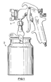
- Figure 1 is a general arrangement showing a conventional spray gun mounted on a cup and being of the kind which can be cleaned economically be use of the apparatus provided by this invention,
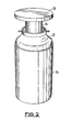
- Figure 2 is a perspective view of soaking apparatus provided by this invention showing a spray gun cup and the associated apparatus in situ,
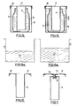
- Figure 3 illustrates diagrammatically a typical conventional soaking apparatus with an adjacent indication in Figure 3a of the amount of solvent required in use,
- Figures 4, 5 and 6 are diagrammatic sectional views showing three functions of soaking apparatus according to this invention with an adjacent indication in Figures 4a, 5a and 6a respectively of the amount of solvent required in comparison with the conventional method of Figure 3,
- Figure 7 is a lid detail according to one embodiment of the invention and,
- Figure 8 is a lid detail according to another embodiment of the invention.
-
It is to be understood that the quantities of solvent shown in the diagrams are not to scale and are only intended to demonstrate the benefit of the invention.
-
With reference to Figure 1 there is shown a typical syphon feed spray gun 1 having a detachable cup 2 of 1.1 litres capacity. In Figure 2 the cup 2 has been detached from the gun 1 and placed in situ with the soaking apparatus of this invention which comprises a cylindrical container 5 of predetermined volume and a circular lid 3 for sealably engaging the rim of the container 5 and having an open ended displacement tube 4 joined centrally of the lid by weld so as to make an air tight joint. The tube 4 has a predetermined volume which is directly related to the volume of the cup 2 and the container 5. The tube 4 is also of predetermined length so that as the lid is secured to the rim of the container 5 it is long enough to push a floating cup 2 into the container 5 for complete immersion of the outside surface thereof without overspill, as shown in Figure 4, but not so long that it will contact the bottom of the cup 2 when the latter rests on the bottom of the container, as shown in Figures 5 and 6. Preferably, there is a clearance of approximately 1cm between the end of the tube and the bottom of the container when the lid is on the container. In use the lid 3 seals with the rim of the container 5 via an annular seal 8 so as to make a substantially air tight joint and the lid is held to the rim by any suitable means such as toggle clamps (not shown).
-
In the example shown in Figures 4 to 6 the apparatus is matched for use with a cup 2 which may have a volume of say 1.1 litres capacity. In which case the volume of the tube 4 may be between 250 and 450ml and is selected to accord with the chosen dimensions of the container, cup and tube in order to provide the desired displacement of solvent in use. The optimum dimensions and predetermined volumes may be calculated mathematically or found by experiment. The criterion is that when it is required to soak the outside of the cup 2 the amount of solvent 7 poured into the container 5 and displaced by the cup 2 will cause the level of the solvent in the container to rise to substantially the rim of the cup thus covering the entire outside surface thereof. Similarly, when it is required to soak the inside of the cup 2 the quantity poured into the cup and displaced by the tube 4 together with the air trapped inside it will cause displacement of the solvent substantially to the rim of the cup thus fully covering the inside surface thereof. The container 5 should be of sufficient depth to accommodate the gun body and prevent spillage to the outside of the container when displacement takes place. If the tube 4 is made longer and the container deeper the neck of the cup 2 will, in use, be well below the rim of the container.
-
Figures 4 to 6 illustrate, the steps of a method of carrying out a cleaning operation on a spray-gun cup 2 using the apparatus provided by this invention. Figure 4 shows by means of a sectional view, the cup 2 exterior soak operation performed by the soaking apparatus. This is achieved by initially dispensing a predetermined amount of solvent 7 into the container 5 using the inside of the tube 4 as a measure. The cup 2 is then placed with the open end uppermost into the container 5 and will rest (float) upon the surface of the solvent therein, at this stage the top rim of the cup 2 will be just below the level of the container 5 top rim, the tube 4 is then inserted into the cup 2 and brought into contact with the centre of the interior base of the cup 2. In order to implement the means of securing the lid 3 onto the container 5, due to the lid 3 being slightly above the container 5, a small amount of downward pressure is applied by hand onto the lid 3 which will in effect, through the tube 4, force the cup 2 down to a position just short of the base of the container 5, and simultaneously displace a quantity of solvent 7 up between the interior of the container 5 and the exterior of the cup 2. With the lid 3 secured onto the container 5 in the sealed position, the tube 4 is able to retain the cup 2 in the submerged position ensuring that the entire exterior surface area of the cup 2 is in contact with a quantity of solvent for the duration of the soak period. An adjacent indication 7 ' of the quantity of solvent required for this operation is shown in Figure 4a. The size of the container 5 is selected to give a volume surrounding the cup which will completely immerse the exterior when the cup is held down by the lid and in this case is say, volume 'C', which could be one tube full, or to a measuring mark on the tube or on the container.
-
Figure 5 shows by means of a sectional view, the cup 2 interior soak operation performed by the soaking apparatus. This is achieved by dispensing a predetermined quantity of solvent 7, amounting to less than the total capacity of the cup 2, into the cup 2 using the inside of the tube 4 as a measure or a level mark on the cup. The cup 2 is than placed into the empty container 5 and will rest on the base of the container 5 or on nibs or ribs (not shown) formed therein to provide a clearance for solvent. The insertion of the tube 4 into the solvent contained in the cup 2 will displace the level of the solvent up to the rim of the cup 2 ensuring that the entire interior surface area of the cup 2 is in contact with a quantity of solvent 7 for the duration of the soak period. An adjacent indication 7' of the quantity of solvent required for this operation is shown in Figure 5a. For this example the required quantity will be approximately 1.1 litres less volume C.
-
Figure 6 shows in the form of a sectional view, the cup 2 full soak operation performed by the soaking apparatus. This is achieved by initially filling the cup 2 to capacity with solvent, the cup 2 is then placed into the empty container 5 and will rest on the base of the container 5, the tube 4 is then inserted in the cup 2, and the lid 3 is secured onto the container 5. The insertion of the tube 4 into the cup 2 will cause by displacement a quantity (volume C) of the solvent contained therein to overflow out of the cup 2 and into the container 5 where it will occupy the space surrounding the cup, thereby ensuring that the entire exterior and interior surface areas of the cup 2 are in contact with a quantity of solvent for the duration of the soak period. An adjacent indication 7' of the amount of solvent required for this operation is shown in Figure 6a. In this operation there is a saving of solvent of approximately volume C.
-
In the embodiment shown in Figures 4 to 6, the lid 3 and the tube 4 are permanently joined and sealed together by means of for example a weld, but it should be understood that further embodiments of the invention affecting the lid 3 and tube 4 arrangement could also be provided without departing from the scope of the appended claims.
-
In one such embodiment as shown in Figure 7 the tube 4 is releasably secured and sealed onto the lid 3 in exactly the same position as previously mentioned by means of for example a screw threaded boss 9 formed on one end of the tube on the inside and a threaded stud 10 secured to the lid 3 to enable the tube 4 to be screwed off and onto the lid 3. An annular gasket 11 is provided to be located between the points of contact, thus providing an air tight and solvent proof seal between the lid 3 and the tube 4. This arrangement permits the lid to be used with a container for soaking gun parts separately.
-
In another embodiment as shown in Figure 8 the lid 3 and the tube 4 are formed from a single piece of material i.e. a metal blank, by means of for example a power press operation, thereby reversing the open and closed end locations of the tube 4 in relation to the lid 3, compared with the two previously mentioned arrangements. That is the displacement tube 4 acts as a solid member but can still be used as a measure.
-
In any of the embodiments described above the combined tube and lid may be used separately for cleaning small brushes. If a bristle brush arrangement (not shown) is provided additionally, located by spring means for example, on the inside surface of the container 5 or on the outside surface of the tube 4, the cleaning operation is finished by manually rotating the lid within the cup and/or the cup within the container.
-
From the foregoing description and drawings it will be appreciated that a method of cleaning a spray gun cup has been provided which reduces the risk of a fire and is more economical in the use of solvent 7, as indicated by the quantities 7' shown diagrammatically in Figures 4a, 5a and 6a, as compared with that in Figure 3a in which any adapted container 6 has been used. It will be further appreciated that although paint contamination will cause an increase in the displacement volume of the cup, or careless measurement an overspill, this will not affect the safety standard of the apparatus as the container is made deep enough to prevent spillage to the outside after displacement has occurred and any inside overspill will flow from the container into the cup or the cup into the container.