EP0214873A2 - Einweichvorrichtung zur Reinigung von Spritzpistolenteilen - Google Patents
Einweichvorrichtung zur Reinigung von Spritzpistolenteilen Download PDFInfo
- Publication number
- EP0214873A2 EP0214873A2 EP86307909A EP86307909A EP0214873A2 EP 0214873 A2 EP0214873 A2 EP 0214873A2 EP 86307909 A EP86307909 A EP 86307909A EP 86307909 A EP86307909 A EP 86307909A EP 0214873 A2 EP0214873 A2 EP 0214873A2
- Authority
- EP
- European Patent Office
- Prior art keywords
- cup
- container
- lid
- solvent
- tube
- Prior art date
- Legal status (The legal status is an assumption and is not a legal conclusion. Google has not performed a legal analysis and makes no representation as to the accuracy of the status listed.)
- Withdrawn
Links
Images

Classifications
-
- B—PERFORMING OPERATIONS; TRANSPORTING
- B05—SPRAYING OR ATOMISING IN GENERAL; APPLYING FLUENT MATERIALS TO SURFACES, IN GENERAL
- B05B—SPRAYING APPARATUS; ATOMISING APPARATUS; NOZZLES
- B05B15/00—Details of spraying plant or spraying apparatus not otherwise provided for; Accessories
- B05B15/50—Arrangements for cleaning; Arrangements for preventing deposits, drying-out or blockage; Arrangements for detecting improper discharge caused by the presence of foreign matter
- B05B15/55—Arrangements for cleaning; Arrangements for preventing deposits, drying-out or blockage; Arrangements for detecting improper discharge caused by the presence of foreign matter using cleaning fluids
Definitions
- This invention relates to soaking apparatus for cleaning the outside and/or inside walls of a paint contaminated spray-gun cup as well as other gun components.
- soaking apparatus for cleaning the outside and/or inside surfaces of a paint contaminated spray-gun cup
- a cylindrical container to serve as a reservoir for containing a liquid solvent
- the container dimensions are closely related to the overall dimensions of the spray gun cup such that the cup may, in use of the apparatus, be freely received entirely within the container with a substantially minimum clearance between the cup walls and the walls of the container
- a lid is provided for said container, the lid being adapted to be releasably secured to the body of said container and capable of forming a substantially air tight seal therewith, and a displacement member joined to the inside face of the lid in a substantially central position which in use extends downwardly into the container to a depth of less than the total depth of the container.
- the displacement member is a tube having an open free end and which, in use, traps a volume of air and enables the tube to displace liquid solvent in the cup to a higher level.
- the tube may be detachably connected to the lid in which case it is important that the joint is sealable to prevent air leaking from the tube during the soak period.
- the tube is formed integrally with the lid such that the free end is closed and the upper end open.
- the tube is of predetermined volume and can be used as a measure when using the apparatus.
- the apparatus may comprise brush means adapted to be located within the container and/or on the outside of the displacement member so as to facilitate cleaning the walls of the cup after soaking.
- the cylindrical container is dimensioned to enable at least the small gun components, such as the spray nozzle and jets, to be soaked simultaneously with the cup body.
- the container is dimensioned to permit the gun body as well as the above-mentioned small components to be soaked in a separate operation, i.e. without the cup. In the latter case an additional sealable lid is provided which does not have a displacement member.
- a range of containers and lids of different sizes may be provided to cater for spray gun cups of different sizes.
- Appropriate liquid level markings for the solvent may be included both on the containers, the tubular displacement members and the cups.
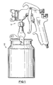
- FIG. 1 With reference to Figure 1 there is shown a typical syphon feed spray gun 1 having a detachable cup 2 of 1.1 litres capacity.
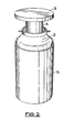
- the cup 2 has been detached from the gun 1 and placed in situ with the soaking apparatus of this invention which comprises a cylindrical container 5 of predetermined volume and a circular lid 3 for sealably engaging the rim of the container 5 and having an open ended displacement tube 4 joined centrally of the lid by weld so as to make an air tight joint.
- the tube 4 has a predetermined volume which is directly related to the volume of the cup 2 and the container 5.
- the tube 4 is also of predetermined length so that as the lid is secured to the rim of the container 5 it is long enough to push a floating cup 2 into the container 5 for complete immersion of the outside surface thereof without overspill, as shown in Figure 4, but not so long that it will contact the bottom of the cup 2 when the latter rests on the bottom of the container, as shown in Figures 5 and 6.
- the lid 3 seals with the rim of the container 5 via an annular seal 8 so as to make a substantially air tight joint and the lid is held to the rim by any suitable means such as toggle clamps (not shown).
- the apparatus is matched for use with a cup 2 which may have a volume of say 1.1 litres capacity.
- the volume of the tube 4 may be between 250 and 450ml and is selected to accord with the chosen dimensions of the container, cup and tube in order to provide the desired displacement of solvent in use.
- the optimum dimensions and predetermined volumes may be calculated mathematically or found by experiment.
- the criterion is that when it is required to soak the outside of the cup 2 the amount of solvent 7 poured into the container 5 and displaced by the cup 2 will cause the level of the solvent in the container to rise to substantially the rim of the cup thus covering the entire outside surface thereof.
- the quantity poured into the cup and displaced by the tube 4 together with the air trapped inside it will cause displacement of the solvent substantially to the rim of the cup thus fully covering the inside surface thereof.
- the container 5 should be of sufficient depth to accommodate the gun body and prevent spillage to the outside of the container when displacement takes place. If the tube 4 is made longer and the container deeper the neck of the cup 2 will, in use, be well below the rim of the container.
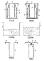
- Figures 4 to 6 illustrate, the steps of a method of carrying out a cleaning operation on a spray-gun cup 2 using the apparatus provided by this invention.
- Figure 4 shows by means of a sectional view, the cup 2 exterior soak operation performed by the soaking apparatus. This is achieved by initially dispensing a predetermined amount of solvent 7 into the container 5 using the inside of the tube 4 as a measure. The cup 2 is then placed with the open end uppermost into the container 5 and will rest (float) upon the surface of the solvent therein, at this stage the top rim of the cup 2 will be just below the level of the container 5 top rim, the tube 4 is then inserted into the cup 2 and brought into contact with the centre of the interior base of the cup 2.
- the size of the container 5 is selected to give a volume surrounding the cup which will completely immerse the exterior when the cup is held down by the lid and in this case is say, volume 'C', which could be one tube full, or to a measuring mark on the tube or on the container.
- Figure 5 shows by means of a sectional view, the cup 2 interior soak operation performed by the soaking apparatus. This is achieved by dispensing a predetermined quantity of solvent 7, amounting to less than the total capacity of the cup 2, into the cup 2 using the inside of the tube 4 as a measure or a level mark on the cup.
- the cup 2 is than placed into the empty container 5 and will rest on the base of the container 5 or on nibs or ribs (not shown) formed therein to provide a clearance for solvent.
- the insertion of the tube 4 into the solvent contained in the cup 2 will displace the level of the solvent up to the rim of the cup 2 ensuring that the entire interior surface area of the cup 2 is in contact with a quantity of solvent 7 for the duration of the soak period.
- An adjacent indication 7' of the quantity of solvent required for this operation is shown in Figure 5a. For this example the required quantity will be approximately 1.1 litres less volume C.
- Figure 6 shows in the form of a sectional view, the cup 2 full soak operation performed by the soaking apparatus. This is achieved by initially filling the cup 2 to capacity with solvent, the cup 2 is then placed into the empty container 5 and will rest on the base of the container 5, the tube 4 is then inserted in the cup 2, and the lid 3 is secured onto the container 5. The insertion of the tube 4 into the cup 2 will cause by displacement a quantity (volume C) of the solvent contained therein to overflow out of the cup 2 and into the container 5 where it will occupy the space surrounding the cup, thereby ensuring that the entire exterior and interior surface areas of the cup 2 are in contact with a quantity of solvent for the duration of the soak period.
- An adjacent indication 7' of the amount of solvent required for this operation is shown in Figure 6a. In this operation there is a saving of solvent of approximately volume C.
- the lid 3 and the tube 4 are permanently joined and sealed together by means of for example a weld, but it should be understood that further embodiments of the invention affecting the lid 3 and tube 4 arrangement could also be provided without departing from the scope of the appended claims.
- the tube 4 is releasably secured and sealed onto the lid 3 in exactly the same position as previously mentioned by means of for example a screw threaded boss 9 formed on one end of the tube on the inside and a threaded stud 10 secured to the lid 3 to enable the tube 4 to be screwed off and onto the lid 3.
- An annular gasket 11 is provided to be located between the points of contact, thus providing an air tight and solvent proof seal between the lid 3 and the tube 4. This arrangement permits the lid to be used with a container for soaking gun parts separately.
- the lid 3 and the tube 4 are formed from a single piece of material i.e. a metal blank, by means of for example a power press operation, thereby reversing the open and closed end locations of the tube 4 in relation to the lid 3, compared with the two previously mentioned arrangements. That is the displacement tube 4 acts as a solid member but can still be used as a measure.
- the combined tube and lid may be used separately for cleaning small brushes.
- a bristle brush arrangement (not shown) is provided additionally, located by spring means for example, on the inside surface of the container 5 or on the outside surface of the tube 4, the cleaning operation is finished by manually rotating the lid within the cup and/or the cup within the container.
Landscapes
- Spray Control Apparatus (AREA)
- Cleaning By Liquid Or Steam (AREA)
Priority Applications (1)
| Application Number | Priority Date | Filing Date | Title |
|---|---|---|---|
| GB08509362A GB2173489A (en) | 1985-04-12 | 1985-04-12 | Soaking apparatus |
Applications Claiming Priority (1)
| Application Number | Priority Date | Filing Date | Title |
|---|---|---|---|
| GB08509362A GB2173489A (en) | 1985-04-12 | 1985-04-12 | Soaking apparatus |
Publications (2)
| Publication Number | Publication Date |
|---|---|
| EP0214873A2 true EP0214873A2 (de) | 1987-03-18 |
| EP0214873A3 EP0214873A3 (de) | 1987-09-09 |
Family
ID=10577510
Family Applications (1)
| Application Number | Title | Priority Date | Filing Date |
|---|---|---|---|
| EP86307909A Withdrawn EP0214873A3 (de) | 1985-04-12 | 1986-10-13 | Einweichvorrichtung zur Reinigung von Spritzpistolenteilen |
Country Status (1)
| Country | Link |
|---|---|
| EP (1) | EP0214873A3 (de) |
Cited By (1)
| Publication number | Priority date | Publication date | Assignee | Title |
|---|---|---|---|---|
| GB2493531A (en) * | 2011-08-09 | 2013-02-13 | Helen Kirkham | Grill cleaning method and container |
Family Cites Families (4)
| Publication number | Priority date | Publication date | Assignee | Title |
|---|---|---|---|---|
| GB911908A (de) * | 1900-01-01 | |||
| DE117722C (de) * | ||||
| US4334548A (en) * | 1981-02-13 | 1982-06-15 | Daiwa Can Company | Apparatus for defatting treatment of containers |
| GB2122980B (en) * | 1982-07-08 | 1985-12-24 | Techno Pack | Method and apparatus for cleansing containers |
-
1986
- 1986-10-13 EP EP86307909A patent/EP0214873A3/de not_active Withdrawn
Cited By (2)
| Publication number | Priority date | Publication date | Assignee | Title |
|---|---|---|---|---|
| GB2493531A (en) * | 2011-08-09 | 2013-02-13 | Helen Kirkham | Grill cleaning method and container |
| GB2493531B (en) * | 2011-08-09 | 2013-07-17 | Helen Kirkham | Grill cleaning method and container |
Also Published As
| Publication number | Publication date |
|---|---|
| EP0214873A3 (de) | 1987-09-09 |
Similar Documents
| Publication | Publication Date | Title |
|---|---|---|
| US5992617A (en) | Painting implement keeper | |
| US5031798A (en) | Spraying device | |
| US7083044B1 (en) | Deep-set paint pan with a form fitted lid | |
| US2873881A (en) | Container rim protector | |
| US4022344A (en) | Attachment for a liquid container | |
| US4020968A (en) | Container rim guard and extension device | |
| US2786614A (en) | Attachment for paint cans or the like | |
| US6715647B1 (en) | Funnel with support assembly | |
| US9522568B2 (en) | Paint can saver apparatus | |
| US20020000388A1 (en) | Paint brush storage lid | |
| GB2292309A (en) | A Brush rest | |
| US5004118A (en) | Container cover | |
| US4903869A (en) | Brush storage and fluid dispensing device | |
| EP0214873A2 (de) | Einweichvorrichtung zur Reinigung von Spritzpistolenteilen | |
| CA2476526C (en) | A container for roller-applied coating compositions and its use in coating procedures for rough surfaces | |
| EP1297972B1 (de) | Behälter für, mittels eines Farbrollers auftragbare Beschichtungszusammensetzungen und dessen Verwendung in Beschichtungsverfahren für rauhe Oberflächen | |
| GB2141413A (en) | Paintsaver | |
| US5477873A (en) | Artist's brush washing apparatus | |
| US2660063A (en) | Sample taking device | |
| EP0102668B1 (de) | Flüssigkeitsfüllrohr mit rechteckigem Endabschnitt | |
| US3191799A (en) | Safety float valve | |
| GB2173489A (en) | Soaking apparatus | |
| US683892A (en) | Holder for paste, mucilage, &c. | |
| EP0504941A1 (de) | Behälter für Farben | |
| SU461026A1 (ru) | Емкость дл хранени и распределени в зких жидкостей |
Legal Events
| Date | Code | Title | Description |
|---|---|---|---|
| PUAI | Public reference made under article 153(3) epc to a published international application that has entered the european phase |
Free format text: ORIGINAL CODE: 0009012 |
|
| AK | Designated contracting states |
Kind code of ref document: A2 Designated state(s): DE ES FR GB IT SE |
|
| PUAL | Search report despatched |
Free format text: ORIGINAL CODE: 0009013 |
|
| RHK1 | Main classification (correction) |
Ipc: B08B 3/04 |
|
| AK | Designated contracting states |
Kind code of ref document: A3 Designated state(s): DE ES FR GB IT SE |
|
| 17P | Request for examination filed |
Effective date: 19880304 |
|
| 17Q | First examination report despatched |
Effective date: 19881202 |
|
| STAA | Information on the status of an ep patent application or granted ep patent |
Free format text: STATUS: THE APPLICATION IS DEEMED TO BE WITHDRAWN |
|
| 18D | Application deemed to be withdrawn |
Effective date: 19890413 |