EP0214784B1 - Finned heat transfer device and method for making same - Google Patents
Finned heat transfer device and method for making same Download PDFInfo
- Publication number
- EP0214784B1 EP0214784B1 EP86306379A EP86306379A EP0214784B1 EP 0214784 B1 EP0214784 B1 EP 0214784B1 EP 86306379 A EP86306379 A EP 86306379A EP 86306379 A EP86306379 A EP 86306379A EP 0214784 B1 EP0214784 B1 EP 0214784B1
- Authority
- EP
- European Patent Office
- Prior art keywords
- tube
- strip
- fins
- heat transfer
- leg members
- Prior art date
- Legal status (The legal status is an assumption and is not a legal conclusion. Google has not performed a legal analysis and makes no representation as to the accuracy of the status listed.)
- Expired - Lifetime
Links
Images


Classifications
-
- F—MECHANICAL ENGINEERING; LIGHTING; HEATING; WEAPONS; BLASTING
- F28—HEAT EXCHANGE IN GENERAL
- F28F—DETAILS OF HEAT-EXCHANGE AND HEAT-TRANSFER APPARATUS, OF GENERAL APPLICATION
- F28F1/00—Tubular elements; Assemblies of tubular elements
- F28F1/10—Tubular elements and assemblies thereof with means for increasing heat-transfer area, e.g. with fins, with projections, with recesses
- F28F1/12—Tubular elements and assemblies thereof with means for increasing heat-transfer area, e.g. with fins, with projections, with recesses the means being only outside the tubular element
- F28F1/24—Tubular elements and assemblies thereof with means for increasing heat-transfer area, e.g. with fins, with projections, with recesses the means being only outside the tubular element and extending transversely
- F28F1/30—Tubular elements and assemblies thereof with means for increasing heat-transfer area, e.g. with fins, with projections, with recesses the means being only outside the tubular element and extending transversely the means being attachable to the element
-
- F—MECHANICAL ENGINEERING; LIGHTING; HEATING; WEAPONS; BLASTING
- F28—HEAT EXCHANGE IN GENERAL
- F28F—DETAILS OF HEAT-EXCHANGE AND HEAT-TRANSFER APPARATUS, OF GENERAL APPLICATION
- F28F1/00—Tubular elements; Assemblies of tubular elements
- F28F1/10—Tubular elements and assemblies thereof with means for increasing heat-transfer area, e.g. with fins, with projections, with recesses
- F28F1/12—Tubular elements and assemblies thereof with means for increasing heat-transfer area, e.g. with fins, with projections, with recesses the means being only outside the tubular element
- F28F1/34—Tubular elements and assemblies thereof with means for increasing heat-transfer area, e.g. with fins, with projections, with recesses the means being only outside the tubular element and extending obliquely
- F28F1/36—Tubular elements and assemblies thereof with means for increasing heat-transfer area, e.g. with fins, with projections, with recesses the means being only outside the tubular element and extending obliquely the means being helically wound fins or wire spirals
-
- B—PERFORMING OPERATIONS; TRANSPORTING
- B21—MECHANICAL METAL-WORKING WITHOUT ESSENTIALLY REMOVING MATERIAL; PUNCHING METAL
- B21C—MANUFACTURE OF METAL SHEETS, WIRE, RODS, TUBES OR PROFILES, OTHERWISE THAN BY ROLLING; AUXILIARY OPERATIONS USED IN CONNECTION WITH METAL-WORKING WITHOUT ESSENTIALLY REMOVING MATERIAL
- B21C37/00—Manufacture of metal sheets, bars, wire, tubes or like semi-manufactured products, not otherwise provided for; Manufacture of tubes of special shape
- B21C37/06—Manufacture of metal sheets, bars, wire, tubes or like semi-manufactured products, not otherwise provided for; Manufacture of tubes of special shape of tubes or metal hoses; Combined procedures for making tubes, e.g. for making multi-wall tubes
- B21C37/15—Making tubes of special shape; Making tube fittings
- B21C37/22—Making finned or ribbed tubes by fixing strip or like material to tubes
- B21C37/26—Making finned or ribbed tubes by fixing strip or like material to tubes helically-ribbed tubes
Definitions
- the present invention relates to an improved heat transfer fin for a finned heat transfer device, and to an improved process and apparatus for making and applying the same to a tube.
- refrigerant-carrying tube In refrigeration and air conditioning applications it is common to utilize a refrigerant-carrying tube as the means by which heat is removed from a chamber or areas to be cooled, and to flow air across the refrigerant-carrying tube to assist in transferring heat to or from the tube wall as imparted by the heat of vaporization or condensation of the refrigerant within the tube.
- the refrigerant carrying tubes usually constitute either a condenser or an evaporator.
- the refrigerant has a significantly greater ability to transfer heat to the tube in which it is carried than does the air which flows across its exterior.
- it is an accepted practice in the refrigeration art to substantially increase the surface area provided on the outside, or airside, of the tube. Most often, the increased surface area is provided in the form of some sort of extended cooling surface or fin extending from the tube outer surface.
- extended cooling surface or fin extending from the tube outer surface.
- Many types of finned tubing are commercially available for use in refrigerant-to- air heat exchangers (both evaporators and condensers).
- One type of extended surface fin is that known as a "spine fin", as disclosed in my prior U.S. Patent 2,983,300.
- the spine fin has a disadvantage in that it is mechanically weak and has a low resistance to bending and compressive forces. Therefore, to permit its practical utilization the spine fins are spaced very closely on the refrigerant tube.
- Other types of extended surface fins are disclosed for example in U.S. Patent No. 4,143,710, issued to LaPorte et al; these latter fins are complex geometric shapes, which are difficult to fabricate and have a higher degree of waste material in relation the heat transfer capacity provided.
- DE-C-1,1 08,716 discloses the use of a mounting flange in continuous close contact with the tube and fins formed integrally with the mounting flange and extending radially outward from the mounting flange.
- the present invention provides a new form of fin structure which facilitates a solution to the dual problems of frost bridging and insufficient mechanical strength.
- Preferred forms of fin structure according to the invention greatly reduce frost bridging and will function in an environment where the convection air forced across the fins is below the freezing point of water, while at the same time maintaining sufficient mechanical strength to permit pragmatic utilization.
- a finned heat transfer device providing heat transfer to and from a tube for containing a heat transfer fluid and comprising an integrally formed chain of heat conductive fins wound helically under tension round the tube, said chain comprising continuous mounting flange means in continuous snug contact with the tube and fins formed integrally with the mounting flange means and extending radially outward therefrom characterized in that the continuous mounting flange means comprises two axially-spaced parallel helically extending flanges both of which are in continuous contact with the tube and in that each fin comprises two leg members formed integrally with the two flanges respectively and a bridge member interconnecting and formed integrally with the two leg members respectively, said leg members and said mounting flanges being provided in preselected dimensions in relation to each other to substantially reduce frost bridging between adjacent fins.
- apparatus for making a finned heat transfer device comprising, in combination means for feeding an elongate strip of thermally conductive material, means for forming the strip into an integrally formed chain of heat conductive fins with continuous mounting flange means, and winding the formed strip helically about a tube with the flange means thereof in continuous snug contact with the tube, characterised by means for transversely lancing said strip into an intermediate configuration ( Figure 6) having a pair of imperforate opposed side mounting portions interconnected by a lanced web portion and means for stretching and reforming said intermediate configuration into a subsequent configuration comprising an integrally formed chain of a plurality of looped fins, said chain having a respective mounting flange formed from each of said imperforate opposed side portions, and each of said fins comprising two vertical leg members extending outwardly from a respective one of said mounting flanges and a bridge portion connecting said leg members to one another at the distal end of said leg member, said leg
- the fins are wound on the tube at a pitch from substantially 1 to 2 per cm.
- the looped fin chain 3 of the present invention is fabricated in a unitary process employing apparatus that combines several work stations which cooperate to produce and apply the formed looped fin chain 3 immediately to a tube 4.
- a coil 1 of thin sheet metal 2 for example, aluminum of the 3003 or 1100 alloy type, is disposed horizontally around a series of work stations A through D arranged generally vertically over a table 15 and within the core of the coil 1, all of which rotate in the direction shown by arrow 16 around the tube 4, which is fed vertically longitudinally along its own axis at approximately the center of the coil 1 in the direction shown by arrow 5.
- An apparatus of this kind is described in U.S. Patent No. 3,134,166 issued to Venables.
- the stock 2 is drawn from the coil 1 by its engagement between two lance cutter rolls 6 and 7 which comprise work station A and which cooperate in their rotation to pull the fin stock 2 therethrough.
- the equipment and processes for producing a series of slits through a moving thin metal strip are generally known, and in this embodiment the cutter rolls 6 and 7 are both equipped with radial cutting teeth 18 which intermesh as the fin stock 2 is fed therebetween, as is shown in more detail in Figure 5.
- the lance cutter 7 is equipped with flanges of selected vertical dimension and constitutes a "female” cutter, while the lance cutter 6 engages in the space between the flanges and constitutes a "male” cutter.
- the width of the fin stock 2 is greater than that of the lance cutters 6 and 7, so that it is formed into a shallow lanced generally channel shaped form shown in Figure 6, with the unlanced portions 8 and 9 of the fin stock extending perpendicularly to the lanced central portion, which has a series of closely spaced transverse fin preforms 10 formed therein by a series of parallel transverse slits produced by the intermeshing teeth 18.
- the lanced and channeled fin stock is then drawn between matched cooperating forming rolls 12 and 13 of selected dimension located at work station B, which stretch preform and final-U-form the fin preforms 10 to the required "looped fin" configuration.
- stretch preforming enables the lanced channel to be formed into the required deep U-form in a single processing step. This may be compared, for example, with the process described in U.S. Patent No. 4,224,984, issued to Sharp K. K., in which multiple forming steps are required to produce its shaped heat transfer fin.
- the center line through the axes of the form rolls 12 and 13 of work station B is oriented at preselected angle a in relation to the center line through the axes of lance cutters 6 and 7 of work station A, with the result that the lanced channel 2 is placed in tension as it is pulled around the male forming roll 12 before being pulled through the interface of the two forming rolls.
- each of which fins comprises a pair of generally vertical leg members 10a and 10b connected by a bridge portion 10c, and having relatively short mounting flanges 8 and 9 substantially parallel to the bridge portion 10c extending perpendicularly from each vertical leg member.
- the integral chain is then fed around guide roll 11 at work station C, preparatory to being helically wound under tension around the tube 4 at work station D in an inverted fashion, the base flanges 8 and 9 of the looped fins being applied in contact with the outer periphery 4a of the tube 4, the looped fins being disposed generally longitudinally of the length of the tube, and the bridge portions 10c of the looped fins being disposed generally circumferentially and outwardly in relation to the tube periphery 4a.
- the chain 3 is wound on the tube the fins separate from one another with a progressively increasing circumferential spacing as the radial distance increases from surface 4a of the tube.
- the chain is wound so that the immediately adjacent portions of base flanges 8 and 9 of successive turns butt as closely as possible tightly against one another, so as to minimize the space between them.
- the tension applied to the chain 3 as it is wound around the tube assures adequate contact between the base flanges of the looped fin stock and the outer periphery of the tube stock which promotes mechanical contact providing a good heat transfer relationship between the looped fin and the tube.
- Guide roll 11 is disposed with its rotation axis at a selected angle (3 which permits the looped fin structure to approach the tube stock at the selected helix angle 8.
- the angle 8 is 19° when wrapping at a pitch of 1 looped fin per centimetre (2 1/2 looped fins per inch).
- the looped fin chain 3 is made to preselected dimensions and is helically wound around the refrigerant tube 4 at a preselected pitch or distance between adjacent rows, so that the fins are spaced far enough apart in all three directions, namely radially from the mounting flange tips 8 and 9 to the bridge portion 10c, circumferentially between the generally parallel vertical members 10a and 10b and longitudinally between successive helical wraps (spaces 14 in Figures 2 and 2A).
- the bridge portion 10c when such a lanced channel is stretch preformed and worked into the final looped fin chain configuration 3, the bridge portion 10c will be approximately 0.5 cm (0.200 inch) wide, while the vertical members 10a and 10b will each be approximately 0.75 cm (0.300 inch) in length.
- the resultant element is to be used for a domestic refrigerator or air conditioner and the diameter of the tube 4 employed is 0.94 cm (0.375 inch), the fins being wound at a pitch of 2 per cm (5 per inch).
- each flange 8 and 9 is 0.16 cm (0.0625 inch)
- the length of each leg member is 0.95 cm (0.375 inch)
- the bridge member reduces to 0.32 cm (0.125 inch).
- the distance from the exterior surface 4a of the tube to the outermost part of the bridge member 10c can be characterized as about equal to the tube diameter.
- the distance 14 ( Figures 2 and 2A) between the helical rows is generally controlled by the width to which the mounting flange tips 8 and 9 have been formed, the pitch of the rotation of fin stock 2 and the rate of longitudinal feed of the tube stock 4 being arranged so that the tips 8 and 9 of adjacent turns are contiguous to each other; the distance 14 between adjacent helical rows will therefore be nominally double the length of each connecting flange, namely 0.5 cm (0.200 inch) and 0.32 cm (0.125 inch) in these examples.
- These dimensions which are exemplary only, have been found effective to prevent frost bridging with a refrigerant tube, while providing sufficient mechanical strength to permit pragmatic industrial use.
- Alternative materials for the fin stock are copper and steel.
- a refrigerator or air conditioner heat exchanger assembly will comprise a predetermined length of the pipe 4 having a corresponding length of the chain 3 mounted thereon while straight and then bent to the required shape.
- the tensioned chain is fastened to the pipe at least at its two ends by any suitable means, such as mechanical clamps, welding, or a suitable glue or cement.
- the chain can also be retained under tension on the tube by fastening the butting mounting flanges 8 and 9 to one another by any of these means so as to prevent relative longitudinal movement between them, at least at the two ends of the chain, and perhaps also at intermediate points.
- the lancing of the strip produces a small stretch of the unlanced side portions 8 and 9, but to an extent of less than about 0.5% of the strip length.
- a much greater extension is produced during the stretch forming between the form rolls 12 and 13, and the amount of tension that is required usually is such as to produce an extension of about 1% to 2.5% in length of the flanges 8 and 9, usually in the range 2% to 2.5%.
- Another extension is produced by the wrapping tension of the order of 1 % to 1.5% in length.
- the total extension produced by the process must of course be within the yield limit of the material, and for a hard aluminum (or alloy) this will be about 4%, while for softer aluminum (or alloy) this will be of the order of 5% to 6%.
- the extension produced by the lancing is due to the spreading action of the cutting blades, irrespective of their speed, and appropriate forming and wrapping tensions may be maintained by adjusting the respective drive to feed out the required smaller length of lanced fin stock than would be required in the absence of tension, or by utilizing tension sensing devices controlling variable speed mechanisms between the lance cutter drive, the forming roll drive, and the tube rotating drive.
- the fin leg members 10a and 10b be essentially parallel to each other as shown in Figure 3A to provide optimum distance between fin members to minimize frost bridging.
- the bridge portion 10c is optimum when it is essentially flat and substantially parallel to the mounting flange tips 8 and 9, again as shown in Figure 3A, but variations to this optimum configuration can be tolerated with only slight degradation in performance, as measured by resistance to frost bridging promotion and resistance to deformation during fabrication and application. For example, a slight radius 10r at the intersections of portions 10a and 10b with portion 10c, as shown in Figure 3A, will have only a slight effect in reducing resistance to frost bridging.
- portion 10c Decreasing the length of portion 10c, for example as shown in Figure 3C by utilizing angular leg portions 10d, and as shown Figure 3D by inclining the leg portions 10a and 10b toward one another, results in shapes which have a greater tendency to hold defrost water by surface energy within the shortened dimension.
- the water is held in the form of a meniscus 17, which shields the fin legs and bridge portion and thereby reduces the effective fin surface area available for effective heat transfer as shown by the cross-hatched area of Figures 15 and 16.
- the dimension of the bridge 10c, or the equivalent dimension between the leg portions is correlated with the fin pitch, or the number of turns per unit length of tube. For refrigerator and air conditioning applications the practical maximum is about 3 turns per cm (about 8 turns per inch).
- it is preferred that the approximate minimum dimension of portion 10c to prevent such water meniscus retention and frost bridging should not be reduced below 0.32 cm (0.125 inch).
- Such dimensions are exemplary only.
- Stretch preforming as employed in this invention is a novel process whereby the lanced channel produced from the strip 2 is progressively formed into an approximate U-shape in a single forming step as the lanced channel progresses around the circumference of male roll 12 in its approach to the tangent contact point with female roll 13.
- Stretch preforming is accomplished in this embodiment by providing the two rolls with complementary shoulders 12s and 13s between which the flange tips 8 and 9 pass and are gripped thereby, and by operating the work station B form rolls 12 and 13 at approximately 1% to 2.5% higher peripheral speed than the rate at which the lanced channel is fed out of the lance cutters 6 and 7 at work station A.
- This tension acts to progressively bend the lanced center strips 10 into a sufficiently preformed U-shape appropriate for entering the intermesh of form rolls 12 and 13 where the final U-shape is produced at their point of tangency.
- a distance C D ( Figure 8) between the centers of the form rolls 12 and 13 is selected which provides sufficient contact friction of the rolls to mounting flange tips 8 and 9 to provide sufficient tension in preforming the U-shape, but which allows adequate slippage to prevent exceeding the elastic limit of the selected fin material.
- An alternative method of providing adequate frictional drive without exceeding the elastic limit of the selected fin material involves spring loading the bearing support of either roll 12 or 13 to provide a floating or variable center distance C D, such spring loading accommodating minor variations in the thickness of the fin stock 2 and the imperforate unlanced mounting flange tips 8 and 9.
- a second alternative to accomplish the same result can be the provision of a slip clutch in the drive shaft of the drive to the form rolls 12 and 13.
- Other methods generally known in the art could also be employed to provide the needed tension and, if needed, slippage of the generally U-shaped fin stock as it passes through form rolls 12 and 13.
- Figure 10 shows an alternative arrangement of forming rolls for employment at station B to provide final U-forming after stretch preforming, in which the single female form roll 13 is replaced by two angular rolls 13a, 13b, which respectively engage the side portions 10a and 10b, and back up roll 13c which engages cross portion 10c and maintains it flat.
- angle a when angle a is approximately 90°, stretch preforming occurs throughout an arc of y of between 80° and 90°, preferably approximately 85°, and the corresponding leading angle ⁇ is between 20° and 30°, with a preferred value of approximately 25°.
- Figure 14b shows that angle a may range from a minimum 60° to a maximum of at least 180° when the two lines are parallel so as to accommodate work stations in other arrangements besides that described above.
- FIG. 12 Another alternative apparatus and method of making the loop fin of the present invention is shown in Figure 12.
- a lance station H performs only the lancing function and all final Innn fin fnrminn ic performed a fnrminn station J.
- Lance station H is similar to that described earlier in relation to Figures 4 and 5 except that the flanges have been removed from "female" lance cutter 7. Since the width of the fin stock 2 is greater than the width of the lance cutters 6 and 7, it emerges from lance station H as a flat center lanced strip with fin preforms 10a, the imperforate unlanced portions 8a and 9a extending on each side of the slits 11, as shown in Figure 13.
- An idler roll 20 at station I is located in such a manner as to guide the flat center lanced stock and cause it to approach form roll 12 at the required approach angle a prior to contact therewith.
- As the stock contacts form roll 12 it is stretch preformed around an arc y of the roll until stretch preforming is complete prior to the intermesh between the two rolls, where any remaining final U-forming is accomplished, and the stock emerges in the loop fin configuration 3 as shown in Figure 9.
- an idler roll 20 allows parallel alignment of the lance and form stations.
- Idler roll 20 aids in the critical step of stretch preforming in the process depicted in Figure 12 by providing an adequate angle of approach a.
- the tension on imperforate unlanced portions 8a and 9a is provided by operating the cooperating forming rolls 12 and 13 or work station J at a slightly higher peripheral speed than the cooperating lance cutters 6 and 7 of work station H.
- sufficient stretch preforming occurs if work station J is operated at a peripheral speed approximately 1% greater than work station H.
- Work station J functions and operates essentially the same as work station B of Figure 1 to provide the final looped fin configuration 3.
- the looped fin chain 3 After exiting from work station J the looped fin chain 3 is wound onto the tubing 4 at work station K, with the helix angle controlled by the longitudinal speed of the tube 4 along the line of arrow 5 and the rate of rotation of tube 4 as it travels in that direction.
Landscapes
- Engineering & Computer Science (AREA)
- Physics & Mathematics (AREA)
- Mechanical Engineering (AREA)
- Geometry (AREA)
- Thermal Sciences (AREA)
- General Engineering & Computer Science (AREA)
- Heat-Exchange Devices With Radiators And Conduit Assemblies (AREA)
Description
- The present invention relates to an improved heat transfer fin for a finned heat transfer device, and to an improved process and apparatus for making and applying the same to a tube.
- In refrigeration and air conditioning applications it is common to utilize a refrigerant-carrying tube as the means by which heat is removed from a chamber or areas to be cooled, and to flow air across the refrigerant-carrying tube to assist in transferring heat to or from the tube wall as imparted by the heat of vaporization or condensation of the refrigerant within the tube. In the applications just mentioned, the refrigerant carrying tubes usually constitute either a condenser or an evaporator.
- The refrigerant has a significantly greater ability to transfer heat to the tube in which it is carried than does the air which flows across its exterior. As a result, it is an accepted practice in the refrigeration art to substantially increase the surface area provided on the outside, or airside, of the tube. Most often, the increased surface area is provided in the form of some sort of extended cooling surface or fin extending from the tube outer surface. Many types of finned tubing are commercially available for use in refrigerant-to- air heat exchangers (both evaporators and condensers). One type of extended surface fin is that known as a "spine fin", as disclosed in my prior U.S. Patent 2,983,300. The spine fin has a disadvantage in that it is mechanically weak and has a low resistance to bending and compressive forces. Therefore, to permit its practical utilization the spine fins are spaced very closely on the refrigerant tube. Other types of extended surface fins are disclosed for example in U.S. Patent No. 4,143,710, issued to LaPorte et al; these latter fins are complex geometric shapes, which are difficult to fabricate and have a higher degree of waste material in relation the heat transfer capacity provided.
- These prior art fins have been used successfully for many years to increase the surface area of the air side of refrigerant carrying tubes in home refrigerators and air conditioning units, where the operating temperature of the air flowing across the air side of the tube is above the freezing point of water. However, they have not been so successful in environments where the air temperatures are below freezing, primarily for two reasons:
- (1) because the moisture in the freezing air condenses out and forms a "frost bridge" between the closely spaced spine fins or portions of the geometric fins, which materially inhibits the air flow across and between the fins, and which in turn reduces the heat transfer capability; and
- (2) if the fins are spaced far enough apart to prevent this frost bridging, the resulting structure is mechanically weak.
- DE-C-1,1 08,716 discloses the use of a mounting flange in continuous close contact with the tube and fins formed integrally with the mounting flange and extending radially outward from the mounting flange.
- The present invention provides a new form of fin structure which facilitates a solution to the dual problems of frost bridging and insufficient mechanical strength.
- Preferred forms of fin structure according to the invention greatly reduce frost bridging and will function in an environment where the convection air forced across the fins is below the freezing point of water, while at the same time maintaining sufficient mechanical strength to permit pragmatic utilization.
- It is also an object of the present invention to provide a method of manufacturing a chain of looped fins in which the looped fin stock is applied to refrigerant-carrying tube stock immediately after its formation, so as to minimize the number of steps required in the manufacturing process.
- According to a first aspect of the present invention there is provided a finned heat transfer device providing heat transfer to and from a tube for containing a heat transfer fluid and comprising an integrally formed chain of heat conductive fins wound helically under tension round the tube, said chain comprising continuous mounting flange means in continuous snug contact with the tube and fins formed integrally with the mounting flange means and extending radially outward therefrom characterized in that the continuous mounting flange means comprises two axially-spaced parallel helically extending flanges both of which are in continuous contact with the tube and in that each fin comprises two leg members formed integrally with the two flanges respectively and a bridge member interconnecting and formed integrally with the two leg members respectively, said leg members and said mounting flanges being provided in preselected dimensions in relation to each other to substantially reduce frost bridging between adjacent fins.
- According to a second aspect of the present invention there is provided a method of making a finned heat transfer device providing heat transfer to and from a tube for containing a heat transfer fluid comprising the steps of forming an elongate strip of thermally conductive material into an integrally formed chain of heat conductive fins with continuous mounting flange means, and winding the formed strip helically about a tube with the flange means thereof in continuous snug contact with the tube, characterized by transversely lancing said strip and forming it into an intermediate configuration having a pair of imperforate opposed side mounting flange portion interconnected by a lanced web portion stretch preforming said intermediate configuration to reform the same into a subsequent configuration comprising an integrally formed chain of a plurality of looped fins between said mounting flanges, each of said fins comprising leg members extending outwardly from each of said mounting flanges and a bridge section connecting said leg members at the distal end of said leg members, said leg members and said mounting flanges being provided in preselected dimensions in relation to each other to substantially reduce frost bridging between adjacent fins; and helically winding said chain under tension onto the exterior surface of a tube with the fins extending longitudinally of the tube.
- According to a third aspect of the present invention there is provided apparatus for making a finned heat transfer device, comprising, in combination means for feeding an elongate strip of thermally conductive material, means for forming the strip into an integrally formed chain of heat conductive fins with continuous mounting flange means, and winding the formed strip helically about a tube with the flange means thereof in continuous snug contact with the tube, characterised by means for transversely lancing said strip into an intermediate configuration (Figure 6) having a pair of imperforate opposed side mounting portions interconnected by a lanced web portion and means for stretching and reforming said intermediate configuration into a subsequent configuration comprising an integrally formed chain of a plurality of looped fins, said chain having a respective mounting flange formed from each of said imperforate opposed side portions, and each of said fins comprising two vertical leg members extending outwardly from a respective one of said mounting flanges and a bridge portion connecting said leg members to one another at the distal end of said leg member, said leg members and said mounting flanges being provided in preselected dimensions in relation to each other to substantially reduce frost bridging between adjacent fins.
- It is preferred that the fins are wound on the tube at a pitch from substantially 1 to 2 per cm.
- Particular preferred embodiments of the invention will now be described, by way of example, with reference to the accompanying diagrammatic drawings, wherein:
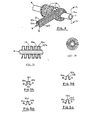
- FIGURE 1 is a schematic perspective view of a first embodiment of apparatus of the invention for fabricating a looped fin structure and mounting it on a cylindrical tube, and also illustrates the corresponding method of the invention;
- FIGURE 2 is a perspective view to a larger scale and showing the stage at which the looped fin structure is mounted on the tube;
- FIGURE 2A is a cross section on the
line 2A-2A in Figure 2; - FIGURE 2B is an end elevation of the assembled structure of Figure 2;
- FIGURE 3A is a cross section through the looped fin structure of Figures 1 and 2, while Figures 3B through 3D are similar cross sections illustrating alternative structures of the invention;
- FIGURE 4 is a plan view of lancing cutting work station A of Figure 1, at which thin metal strip stock is lanced and changed to channel form;
- FIGURE 5 is a side elevation of the work station A;
- FIGURE 6 is a perspective view of the lanced and channel-formed thin metal strip after it emerges from work station A;
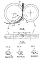
- FIGURE 7 is a plan view of combined stretch forming and U-shape forming work station B of Figure 1;
- FIGURES 7C, 7D and 7E are cross sections on the lines C-C, D-D and E-E of Figure 7 to show the progressive pre-forming of the lanced stock in the work station B;
- FIGURE 8 is a side elevation of the work station B;
- FIGURE 9 is a perspective view of the "looped fin" strip after it emerges from work station B;
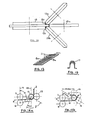
- FIGURE 10 is a perspective view of an alternative apparatus for forming the U-shape corresponding to station B of Figure 1, or station F of Figure 11, or station J of Figure 12;
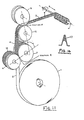
- FIGURE 11 is a perspective view of an alternative apparatus of the invention, and also illustrates a corresponding alternative method of the invention;
- FIGURE 12 is a perspective view of a further alternative apparatus of the invention, and also illustrates a further alternative method of the invention;
- FIGURE 13 is a perspective view of the flat lanced thin metal strip that emerges from station E of the apparatus of Figure 11, or station H of the apparatus of Figure 12;
- FIGURE 14a shows the preferred angular relation (angle a) between a line through the lance roll centers and another line through the form roll centers;
- FIGURE 14b shows the possible range of size of the angle a;
- FIGURE 15 shows a transverse cross section of a loop fin of the invention and the manner in which if moisture is retained it is retained therein; and
- FIGURE 16 shows a similar cross section of a prior art fin structure and the manner in which moisture is retained therein.
- Referring particularly to Figure 1; the looped
fin chain 3 of the present invention is fabricated in a unitary process employing apparatus that combines several work stations which cooperate to produce and apply the formed loopedfin chain 3 immediately to atube 4. In this embodiment acoil 1 of thin sheet metal 2 (fin stock), for example, aluminum of the 3003 or 1100 alloy type, is disposed horizontally around a series of work stations A through D arranged generally vertically over a table 15 and within the core of thecoil 1, all of which rotate in the direction shown byarrow 16 around thetube 4, which is fed vertically longitudinally along its own axis at approximately the center of thecoil 1 in the direction shown byarrow 5. An apparatus of this kind is described in U.S. Patent No. 3,134,166 issued to Venables. - The
stock 2 is drawn from thecoil 1 by its engagement between twolance cutter rolls fin stock 2 therethrough. The equipment and processes for producing a series of slits through a moving thin metal strip are generally known, and in this embodiment thecutter rolls radial cutting teeth 18 which intermesh as thefin stock 2 is fed therebetween, as is shown in more detail in Figure 5. Thelance cutter 7 is equipped with flanges of selected vertical dimension and constitutes a "female" cutter, while thelance cutter 6 engages in the space between the flanges and constitutes a "male" cutter. The width of thefin stock 2 is greater than that of thelance cutters unlanced portions transverse fin preforms 10 formed therein by a series of parallel transverse slits produced by the intermeshingteeth 18. - The lanced and channeled fin stock is then drawn between matched cooperating forming
rolls fin preforms 10 to the required "looped fin" configuration. As discussed in more detail below, stretch preforming enables the lanced channel to be formed into the required deep U-form in a single processing step. This may be compared, for example, with the process described in U.S. Patent No. 4,224,984, issued to Sharp K. K., in which multiple forming steps are required to produce its shaped heat transfer fin. - The center line through the axes of the
form rolls lance cutters lanced channel 2 is placed in tension as it is pulled around themale forming roll 12 before being pulled through the interface of the two forming rolls. By placing work station B at this preselected angle in relation to work station A, and by operating theform rolls lance cutters mounting flange tips form roll 12. This causes the stock to stretch and begin, prior to the point of its tangential contact withform roll 12, to form into a general U-shape which is finalized between theform rolls - As the U-shaped fin stock emerges from work station B the product is now in its final configuration as shown in Figure 9, namely an integrally formed chain of looped fins separated by slits, each of which fins comprises a pair of generally
vertical leg members bridge portion 10c, and having relativelyshort mounting flanges bridge portion 10c extending perpendicularly from each vertical leg member. The integral chain is then fed aroundguide roll 11 at work station C, preparatory to being helically wound under tension around thetube 4 at work station D in an inverted fashion, thebase flanges outer periphery 4a of thetube 4, the looped fins being disposed generally longitudinally of the length of the tube, and thebridge portions 10c of the looped fins being disposed generally circumferentially and outwardly in relation to thetube periphery 4a. As thechain 3 is wound on the tube the fins separate from one another with a progressively increasing circumferential spacing as the radial distance increases fromsurface 4a of the tube. The chain is wound so that the immediately adjacent portions ofbase flanges chain 3 as it is wound around the tube assures adequate contact between the base flanges of the looped fin stock and the outer periphery of the tube stock which promotes mechanical contact providing a good heat transfer relationship between the looped fin and the tube.Guide roll 11 is disposed with its rotation axis at a selected angle (3 which permits the looped fin structure to approach the tube stock at theselected helix angle 8. For example, theangle 8 is 19° when wrapping at a pitch of 1 looped fin per centimetre (2 1/2 looped fins per inch). - Referring now to Figures 2 and 3, in order to provide the most resistance to frost bridging, the looped
fin chain 3 is made to preselected dimensions and is helically wound around therefrigerant tube 4 at a preselected pitch or distance between adjacent rows, so that the fins are spaced far enough apart in all three directions, namely radially from the mountingflange tips bridge portion 10c, circumferentially between the generally parallelvertical members spaces 14 in Figures 2 and 2A). For example, when 0.018 cm (0.007 inch)thick aluminum strip 2 of 2.5 cm (1 inch) width is used for the fin stock, the lancing of such stock withslits 11 that are 2 cm (0.80 inch) long and spaced 0.076 cm (0.030 inch) apart results in unlanced mountingflange tips fin chain configuration 3, thebridge portion 10c will be approximately 0.5 cm (0.200 inch) wide, while thevertical members tube 4 employed is 0.94 cm (0.375 inch), the fins being wound at a pitch of 2 per cm (5 per inch). In another example employed with thesame size tube 4, but with the fins wound at a pitch of 3 per cm (8 per inch), the length of eachflange exterior surface 4a of the tube to the outermost part of thebridge member 10c can be characterized as about equal to the tube diameter. The distance 14 (Figures 2 and 2A) between the helical rows is generally controlled by the width to which the mountingflange tips fin stock 2 and the rate of longitudinal feed of thetube stock 4 being arranged so that thetips distance 14 between adjacent helical rows will therefore be nominally double the length of each connecting flange, namely 0.5 cm (0.200 inch) and 0.32 cm (0.125 inch) in these examples. These dimensions, which are exemplary only, have been found effective to prevent frost bridging with a refrigerant tube, while providing sufficient mechanical strength to permit pragmatic industrial use. Alternative materials for the fin stock are copper and steel. - In commercial practice a refrigerator or air conditioner heat exchanger assembly will comprise a predetermined length of the
pipe 4 having a corresponding length of thechain 3 mounted thereon while straight and then bent to the required shape. The tensioned chain is fastened to the pipe at least at its two ends by any suitable means, such as mechanical clamps, welding, or a suitable glue or cement. The chain can also be retained under tension on the tube by fastening thebutting mounting flanges - It is found that the lancing of the strip produces a small stretch of the
unlanced side portions flanges range 2% to 2.5%. - Another extension is produced by the wrapping tension of the order of 1 % to 1.5% in length. The total extension produced by the process must of course be within the yield limit of the material, and for a hard aluminum (or alloy) this will be about 4%, while for softer aluminum (or alloy) this will be of the order of 5% to 6%. The extension produced by the lancing is due to the spreading action of the cutting blades, irrespective of their speed, and appropriate forming and wrapping tensions may be maintained by adjusting the respective drive to feed out the required smaller length of lanced fin stock than would be required in the absence of tension, or by utilizing tension sensing devices controlling variable speed mechanisms between the lance cutter drive, the forming roll drive, and the tube rotating drive.
- It is preferred that the
fin leg members bridge portion 10c is optimum when it is essentially flat and substantially parallel to the mountingflange tips portions portion 10c, as shown in Figure 3A, will have only a slight effect in reducing resistance to frost bridging. Extending that radius to one half the distance betweenportions portions cross portion 10c as shown in Figures 3C and 15 decreases the resistance to frost bridging, and whencross portion 10c is reduced to zero to form an inverted V-shape as shown in Figure 16, which is the structure disclosed in U.S. Patent No. 4,184,544, issued to Ullmer, the resulting vertex tips provide a nucleating site or focal point which promotes frost formation, which in turn accelerates frost bridging, and shapes with such highly reducedbridge portions 10c are accordingly not effective in minimizing frost bridging. Decreasing the length ofportion 10c, for example as shown in Figure 3C by utilizing angular leg portions 10d, and as shown Figure 3D by inclining theleg portions meniscus 17, which shields the fin legs and bridge portion and thereby reduces the effective fin surface area available for effective heat transfer as shown by the cross-hatched area of Figures 15 and 16. In practice the dimension of thebridge 10c, or the equivalent dimension between the leg portions is correlated with the fin pitch, or the number of turns per unit length of tube. For refrigerator and air conditioning applications the practical maximum is about 3 turns per cm (about 8 turns per inch). Thus, with the particular examples described, it is preferred that the approximate minimum dimension ofportion 10c to prevent such water meniscus retention and frost bridging should not be reduced below 0.32 cm (0.125 inch). Such dimensions, of course, are exemplary only. - Stretch preforming as employed in this invention is a novel process whereby the lanced channel produced from the
strip 2 is progressively formed into an approximate U-shape in a single forming step as the lanced channel progresses around the circumference ofmale roll 12 in its approach to the tangent contact point withfemale roll 13. Stretch preforming is accomplished in this embodiment by providing the two rolls withcomplementary shoulders flange tips lance cutters flange tips - An alternative method of providing adequate frictional drive without exceeding the elastic limit of the selected fin material involves spring loading the bearing support of either roll 12 or 13 to provide a floating or variable center distance C D, such spring loading accommodating minor variations in the thickness of the
fin stock 2 and the imperforate unlanced mountingflange tips - Figure 10 shows an alternative arrangement of forming rolls for employment at station B to provide final U-forming after stretch preforming, in which the single
female form roll 13 is replaced by two angular rolls 13a, 13b, which respectively engage theside portions cross portion 10c and maintains it flat. - Reference to Figures 7 and 14a shows that, when the angle a is approximately 90°, stretch preforming of the lanced channel is accomplished through an arc y of the circumference of the forming
roll 12, the preforming being substantially completed at cross section E-E, before the actual intermesh between the rolls. Where a is approximately 90°, the stretch preforming is accomplished through an arc y of approximately 85° when proper tension is maintained. The stretch preforming of the lanced channel commences at a leading angle w (Figure 14a) prior to intersection of the lanced channel with aline 20 through the axis of formingroll 12 at cross section C-C, which line 20 is parallel to aline 19 through the axes oflance cutters male form roll 12 to point C-C, the imperforate unlanced mountingflange tips roll 12 theflange tips rolls - Alternative machinery arrangements for different methods of making the looped
fin chain 3 of the present invention are disclosed in Figures 11 and 12. In the apparatus of Figure 11 both the rotational and the directional motions are provided to therefrigerant tubing 4. In this apparatus and with this method there are only two work stations, E and F, before the loopedfin 3 is helically applied to thetubing 4. This provides more working or maintenance space between work stations. The requiredhelix approach angle 8 with respect to thetubing 4, determined by the rotational and longitudinal feed rate oftube 4, is provided by appropriate angular placement of the stations E and F with respect to the plane of travel of thetubing 4. It would also be possible to maintain all axes of rotation in parallel orientation by adding an idler roll oriented to the helix angle such as theidler roll 11 of station C in the apparatus of Figure 1. - Another alternative apparatus and method of making the loop fin of the present invention is shown in Figure 12. In this embodiment, a lance station H performs only the lancing function and all final Innn fin fnrminn ic performed a fnrminn station J. Lance station H is similar to that described earlier in relation to Figures 4 and 5 except that the flanges have been removed from "female"
lance cutter 7. Since the width of thefin stock 2 is greater than the width of thelance cutters fin preforms 10a, the imperforateunlanced portions 8a and 9a extending on each side of theslits 11, as shown in Figure 13. - An
idler roll 20 at station I is located in such a manner as to guide the flat center lanced stock and cause it to approachform roll 12 at the required approach angle a prior to contact therewith. As the stock contacts formroll 12 it is stretch preformed around an arc y of the roll until stretch preforming is complete prior to the intermesh between the two rolls, where any remaining final U-forming is accomplished, and the stock emerges in theloop fin configuration 3 as shown in Figure 9. - In the apparatus of Figure 12 it will be seen that the employment of an
idler roll 20 allows parallel alignment of the lance and form stations.Idler roll 20 aids in the critical step of stretch preforming in the process depicted in Figure 12 by providing an adequate angle of approach a. As with the apparatus of Figure 1, the tension on imperforateunlanced portions 8a and 9a is provided by operating the cooperating formingrolls lance cutters fin configuration 3. After exiting from work station J the loopedfin chain 3 is wound onto thetubing 4 at work station K, with the helix angle controlled by the longitudinal speed of thetube 4 along the line ofarrow 5 and the rate of rotation oftube 4 as it travels in that direction.
Claims (38)
Applications Claiming Priority (2)
| Application Number | Priority Date | Filing Date | Title |
|---|---|---|---|
| US76780185A | 1985-08-21 | 1985-08-21 | |
| US767801 | 1985-08-21 |
Publications (2)
| Publication Number | Publication Date |
|---|---|
| EP0214784A1 EP0214784A1 (en) | 1987-03-18 |
| EP0214784B1 true EP0214784B1 (en) | 1990-01-17 |
Family
ID=25080632
Family Applications (1)
| Application Number | Title | Priority Date | Filing Date |
|---|---|---|---|
| EP86306379A Expired - Lifetime EP0214784B1 (en) | 1985-08-21 | 1986-08-18 | Finned heat transfer device and method for making same |
Country Status (10)
| Country | Link |
|---|---|
| EP (1) | EP0214784B1 (en) |
| JP (1) | JPH0697156B2 (en) |
| KR (1) | KR940007196B1 (en) |
| CN (1) | CN1008943B (en) |
| BR (1) | BR8603953A (en) |
| CA (1) | CA1292466C (en) |
| DE (1) | DE3668372D1 (en) |
| ES (1) | ES2001385A6 (en) |
| HK (1) | HK3292A (en) |
| MX (1) | MX170908B (en) |
Families Citing this family (1)
| Publication number | Priority date | Publication date | Assignee | Title |
|---|---|---|---|---|
| GB2223301B (en) * | 1988-07-08 | 1992-12-16 | H E T Limited | Heat exchange device and method of manufacture therefor |
Family Cites Families (10)
| Publication number | Priority date | Publication date | Assignee | Title |
|---|---|---|---|---|
| US2196186A (en) * | 1936-02-14 | 1940-04-09 | Alfred J Berg | Heat exchange element and process of making same |
| GB800265A (en) * | 1956-04-17 | 1958-08-20 | Guy Davies | Improvements in or relating to heat transfer element |
| US3005253A (en) * | 1958-09-26 | 1961-10-24 | Gen Electric | Manufacture of heat exchange tubing |
| DE1402766A1 (en) * | 1960-07-05 | 1969-01-30 | Gustav Rasmussen Fa | Device for helically upright winding a tape onto a rotating tube |
| US3134166A (en) * | 1960-08-26 | 1964-05-26 | Gen Electric | Manufacture of heat exchange tubing |
| FR1288056A (en) * | 1960-11-23 | 1962-03-24 | Process for the manufacture of finned tubes and device for carrying out the process | |
| US3288209A (en) * | 1964-04-13 | 1966-11-29 | Dewandre Co Ltd C | Heat transmitting tubes having helical fin means |
| US3550235A (en) * | 1968-05-15 | 1970-12-29 | Escoa Corp | Method of making a heat exchanger fin tubing |
| ES459078A1 (en) * | 1976-05-25 | 1978-04-01 | Carrier Corp | Spine finned tube |
| US4184544A (en) * | 1977-10-31 | 1980-01-22 | Ullmer Harold J | Apparatus and method for recovering waste heat from flue gases |
-
1986
- 1986-08-01 CA CA000515218A patent/CA1292466C/en not_active Expired - Fee Related
- 1986-08-18 DE DE8686306379T patent/DE3668372D1/en not_active Expired - Fee Related
- 1986-08-18 EP EP86306379A patent/EP0214784B1/en not_active Expired - Lifetime
- 1986-08-19 BR BR8603953A patent/BR8603953A/en not_active IP Right Cessation
- 1986-08-21 JP JP61194100A patent/JPH0697156B2/en not_active Expired - Lifetime
- 1986-08-21 KR KR1019860006920A patent/KR940007196B1/en not_active IP Right Cessation
- 1986-08-21 ES ES8601250A patent/ES2001385A6/en not_active Expired
- 1986-08-21 CN CN86105158A patent/CN1008943B/en not_active Expired
- 1986-08-21 MX MX003501A patent/MX170908B/en unknown
-
1992
- 1992-01-09 HK HK32/92A patent/HK3292A/en unknown
Also Published As
| Publication number | Publication date |
|---|---|
| ES2001385A6 (en) | 1988-05-16 |
| KR940007196B1 (en) | 1994-08-08 |
| CN1008943B (en) | 1990-07-25 |
| CN86105158A (en) | 1987-06-03 |
| KR870002434A (en) | 1987-03-31 |
| JPS6291792A (en) | 1987-04-27 |
| JPH0697156B2 (en) | 1994-11-30 |
| HK3292A (en) | 1992-01-17 |
| DE3668372D1 (en) | 1990-02-22 |
| MX170908B (en) | 1993-09-22 |
| CA1292466C (en) | 1991-11-26 |
| BR8603953A (en) | 1987-03-24 |
| EP0214784A1 (en) | 1987-03-18 |
Similar Documents
| Publication | Publication Date | Title |
|---|---|---|
| US5033544A (en) | Looped fin heat exchanger and method for making same | |
| US4438807A (en) | High performance heat transfer tube | |
| US5934128A (en) | Heat transfer tube having grooved inner surface | |
| JP2006329578A (en) | Method and device for manufacturing inner finned tube | |
| US4425696A (en) | Method of manufacturing a high performance heat transfer tube | |
| US5022149A (en) | Method and apparatus for making a looped fin heat exchanger | |
| JP3489359B2 (en) | Method and apparatus for manufacturing inner spiral grooved tube | |
| US4438808A (en) | Heat exchanger tube | |
| CA2058127C (en) | Inner ribbed tube and method | |
| EP0214784B1 (en) | Finned heat transfer device and method for making same | |
| US5085272A (en) | Spine fin heat exchanger and method and apparatus for producing same | |
| US4381592A (en) | Method of producing helically wound spine fin heat exchanger | |
| US4259771A (en) | Apparatus for producing heat transfer tube | |
| JPH08168817A (en) | Production of heat exchanger having inner groove | |
| CN1147612A (en) | Finned tube and method of fabricating same | |
| JPH0724522A (en) | Heat-transfer tube for absorber and production therefor | |
| JPH09136111A (en) | Fin-tube and production therefor | |
| JP2628712B2 (en) | Method of forming heat transfer surface | |
| JP4632487B2 (en) | Internal grooved heat transfer tube and manufacturing method thereof | |
| KR19980071026A (en) | Sheet for manufacturing fins for heat exchanger and fins for heat exchanger | |
| JP2721253B2 (en) | Heat transfer tube manufacturing method | |
| JPS58187681A (en) | Grooved pipe and its manufacture | |
| JPS5858929A (en) | Manufacture of heat transfer tube | |
| GB2075871A (en) | Improvements in or relating to apparatuses for producing finned tubes for heat transfer | |
| CA1130789A (en) | Heat exchanger tube |
Legal Events
| Date | Code | Title | Description |
|---|---|---|---|
| PUAI | Public reference made under article 153(3) epc to a published international application that has entered the european phase |
Free format text: ORIGINAL CODE: 0009012 |
|
| AK | Designated contracting states |
Kind code of ref document: A1 Designated state(s): DE FR GB IT SE |
|
| 17P | Request for examination filed |
Effective date: 19870915 |
|
| 17Q | First examination report despatched |
Effective date: 19880210 |
|
| GRAA | (expected) grant |
Free format text: ORIGINAL CODE: 0009210 |
|
| AK | Designated contracting states |
Kind code of ref document: B1 Designated state(s): DE FR GB IT SE |
|
| ITF | It: translation for a ep patent filed |
Owner name: BARZANO' E ZANARDO MILANO S.P.A. |
|
| REF | Corresponds to: |
Ref document number: 3668372 Country of ref document: DE Date of ref document: 19900222 |
|
| ET | Fr: translation filed | ||
| PLBE | No opposition filed within time limit |
Free format text: ORIGINAL CODE: 0009261 |
|
| STAA | Information on the status of an ep patent application or granted ep patent |
Free format text: STATUS: NO OPPOSITION FILED WITHIN TIME LIMIT |
|
| 26N | No opposition filed | ||
| ITTA | It: last paid annual fee | ||
| PGFP | Annual fee paid to national office [announced via postgrant information from national office to epo] |
Ref country code: FR Payment date: 19920709 Year of fee payment: 7 |
|
| PGFP | Annual fee paid to national office [announced via postgrant information from national office to epo] |
Ref country code: DE Payment date: 19920713 Year of fee payment: 7 |
|
| PGFP | Annual fee paid to national office [announced via postgrant information from national office to epo] |
Ref country code: SE Payment date: 19920716 Year of fee payment: 7 |
|
| PGFP | Annual fee paid to national office [announced via postgrant information from national office to epo] |
Ref country code: GB Payment date: 19920730 Year of fee payment: 7 |
|
| PG25 | Lapsed in a contracting state [announced via postgrant information from national office to epo] |
Ref country code: GB Effective date: 19930818 |
|
| PG25 | Lapsed in a contracting state [announced via postgrant information from national office to epo] |
Ref country code: SE Effective date: 19930819 |
|
| GBPC | Gb: european patent ceased through non-payment of renewal fee |
Effective date: 19930818 |
|
| PG25 | Lapsed in a contracting state [announced via postgrant information from national office to epo] |
Ref country code: FR Effective date: 19940429 |
|
| PG25 | Lapsed in a contracting state [announced via postgrant information from national office to epo] |
Ref country code: DE Effective date: 19940503 |
|
| REG | Reference to a national code |
Ref country code: FR Ref legal event code: ST |
|
| EUG | Se: european patent has lapsed |
Ref document number: 86306379.8 Effective date: 19940310 |
|
| PG25 | Lapsed in a contracting state [announced via postgrant information from national office to epo] |
Ref country code: IT Free format text: LAPSE BECAUSE OF NON-PAYMENT OF DUE FEES;WARNING: LAPSES OF ITALIAN PATENTS WITH EFFECTIVE DATE BEFORE 2007 MAY HAVE OCCURRED AT ANY TIME BEFORE 2007. THE CORRECT EFFECTIVE DATE MAY BE DIFFERENT FROM THE ONE RECORDED. Effective date: 20050818 |