EP0214726A2 - Récepteur automatique stéréophonique à modulation d'amplitude multisystème utilisant un circuit intégré décodeur stéréophonique à modulation d'amplitude à système unique déjà existant - Google Patents
Récepteur automatique stéréophonique à modulation d'amplitude multisystème utilisant un circuit intégré décodeur stéréophonique à modulation d'amplitude à système unique déjà existant Download PDFInfo
- Publication number
- EP0214726A2 EP0214726A2 EP86305451A EP86305451A EP0214726A2 EP 0214726 A2 EP0214726 A2 EP 0214726A2 EP 86305451 A EP86305451 A EP 86305451A EP 86305451 A EP86305451 A EP 86305451A EP 0214726 A2 EP0214726 A2 EP 0214726A2
- Authority
- EP
- European Patent Office
- Prior art keywords
- signals
- stereo
- terminal
- type
- received
- Prior art date
- Legal status (The legal status is an assumption and is not a legal conclusion. Google has not performed a legal analysis and makes no representation as to the accuracy of the status listed.)
- Granted
Links
- 230000005236 sound signal Effects 0.000 claims description 8
- 238000001514 detection method Methods 0.000 claims description 4
- 230000008878 coupling Effects 0.000 claims description 2
- 238000010168 coupling process Methods 0.000 claims description 2
- 238000005859 coupling reaction Methods 0.000 claims description 2
- 239000011159 matrix material Substances 0.000 description 6
- 239000003990 capacitor Substances 0.000 description 3
- 238000010586 diagram Methods 0.000 description 3
- 238000000034 method Methods 0.000 description 3
- 230000005540 biological transmission Effects 0.000 description 2
- 230000000295 complement effect Effects 0.000 description 1
- 230000002452 interceptive effect Effects 0.000 description 1
- 238000004519 manufacturing process Methods 0.000 description 1
- 230000004048 modification Effects 0.000 description 1
- 238000012986 modification Methods 0.000 description 1
- 230000010363 phase shift Effects 0.000 description 1
- 238000011084 recovery Methods 0.000 description 1
- 239000004065 semiconductor Substances 0.000 description 1
- 230000001360 synchronised effect Effects 0.000 description 1
Images

Classifications
-
- H—ELECTRICITY
- H04—ELECTRIC COMMUNICATION TECHNIQUE
- H04B—TRANSMISSION
- H04B7/00—Radio transmission systems, i.e. using radiation field
-
- H—ELECTRICITY
- H04—ELECTRIC COMMUNICATION TECHNIQUE
- H04H—BROADCAST COMMUNICATION
- H04H20/00—Arrangements for broadcast or for distribution combined with broadcast
- H04H20/44—Arrangements characterised by circuits or components specially adapted for broadcast
- H04H20/46—Arrangements characterised by circuits or components specially adapted for broadcast specially adapted for broadcast systems covered by groups H04H20/53-H04H20/95
- H04H20/47—Arrangements characterised by circuits or components specially adapted for broadcast specially adapted for broadcast systems covered by groups H04H20/53-H04H20/95 specially adapted for stereophonic broadcast systems
- H04H20/49—Arrangements characterised by circuits or components specially adapted for broadcast specially adapted for broadcast systems covered by groups H04H20/53-H04H20/95 specially adapted for stereophonic broadcast systems for AM stereophonic broadcast systems
Definitions
- the FCC Federal Communications Commission
- the FCC did not establish a single-system standard when it authorized stereo AM broadcasting to begin in 1982.
- any system may be used by AM broadcasters so long as it meets certain minimum technical specifications which the FCC imposed.
- four different systems were used by AM broadcasters. These were known as the Harris, Kahn/Hazeltine, Magnavox and Motorola systems. Since then, use of the Harris and Magnavox systems has been effectively discontinued, so that at the time of this writing only the Kahn/Hazeltine and Motorola systems remain in use in the United States.
- a multi-system AM stereo receiver which automatically recognizes and selects appropriate stereo signal decoding circuitry for the particular AM stereo system signal being received at the time.
- Such a receiver must also be compatible with conventional monophonic AM broadcasts.
- receivers should preferably be inexpensive, and for this purpose preferably make use of existing integrated circuits (IC's), instead of requiring the development of new custom IC's in order to achieve this purpose.
- an object of the present invention to provide a multi-system AM stereo receiver which is compatible with monophonic AM broadcasts, and which is capable of receiving and properly decoding AM stereo broadcasts using the Kahn/Hazeltine and Motorola systems, but which does so automatically and using existing IC's.
- an AM stereo receiver capable of receiving signals representative of at least first and second different types of AM stereo systems, but using an integrated circuit (IC) stereo signal decoder designed to properly decode only received signals representing the first type of AM stereo system.
- IC integrated circuit
- Such a receiver includes means for receiving AM radio frequency signals and for converting such signals to corresponding intermediate frequency (IF) signals.
- the receiver also includes first means, including an IC designed to properly decode received IF signals representing the first type of AM stereo system, for developing a first pair of left (L) and right (R) stereo audio signals from received IF signals which represent the first type of AM stereo system.
- the receiver further includes second means, coupled to such IC, for adapting the first means so as to develop a second pair of (L) and (R) stereo audio signals from received IF signals which represent the second type of AM stereo system.
- the receiver includes means coupled to the first and second means for selecting one or the other of such pairs of (L) and (R) stereo audio signals and for coupling the selected pair to (L) and (R) audio outputs of the receiver.
- an AM stereo receiver capable of receiving signals representative of a second type of AM stereo system, but using an IC stereo signal decoder designed to properly decode only received signals representative of a first type of AM stereo system.
- Such a receiver includes means for receiving AM radio frequency signals and for converting such signals to corresponding IF signals.
- the receiver also includes an IC designed to properly decode only IF signals representing the first type of AM stereo system, such IC having a plurality of terminals including: a first terminal at which the IC develops an output signal representative of the envelope of said IF signals; a second terminal for receiving said IF signals as an input thereto; a third terminal at which the IC develops an output error signal "X"; a fourth terminal at which the IC develops an output signal representative of left (L) stereo information; a fifth terminal at which the IC develops an output signal representative of right (R) stereo information; a sixth terminal at which the IC develops an output signal representative of any low frequency phase modulation below about 30Hz in IF signals applied to such second terminal; a seventh terminal for receiving supplied low frequency signals of about 25Hz, and; an eight terminal at which the IC develops an output signal representative of quadrature phase components in said IF signals; means coupled to said third terminal for disabling said error signal; means coupled to said first and eighth terminals for shifting the phase of the signals present at
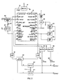
- Fig. 1 makes novel use of an existing commercially available IC known as the MC13020P which is manufactured by the Motorola Corporation. It has been publically announced by Motorola, however, that at least two other companies have been licensed to manufacture this IC. It is understood that a variant of this IC is manufactured by Motorola specially for the General Motors Corporation and bears Delco Part No. DM-235. Although the description of the invention set forth herein refers specifically to the Motorola MC13020P, it will be readily apparent to those skilled in the art that equivalent AM stereo decoder IC's may be substituted, such as the Delco part identified above.
- the Motorola IC is intended to be used in an AM stereo receiver to properly decode in stereo only AM stereo signals which were broadcast using the Motorola compatible quadrature system of AM stereo transmission.
- the receiver can be adapted into one which is capable of also properly decoding AM stereo signals which are broadcast using the Kahn/Hazeltine Independent Sideband system of AM stereo transmission.
- the present invention enables a so-called “single-system” (Motorola) AM stereo receiver, having limited utility, to be readily converted into a so-called “multi-system” (Motorola and Kahn/Hazeltine) AM stereo receiver having greater utility, since presently both AM stereo systems are in use in the United States by AM radio stations.
- Motorola single-system
- multi-system Motorola and Kahn/Hazeltine
- Motorola IC MC13020P denoted in the drawings with the reference numeral 10
- This leaflet also shows the components required external to the IC for operation of the IC as a Motorola AM stereo system decoder. Unless noted herein, those components remain unaffected by the present invention and, for purposes of clarity, are not shown in the drawings.
- the IC has a total of 20 terminals, only 8 of these are affected by the present invention.
- error signal disabling means for example in the form of a capacitor 12 in series with a normally closed electronic switch 14, is connected between terminal 5, the "third terminal", and ground, so that any error signal which may appear at this terminal is suppressed or "killed".
- Phase shifting means in the form of a phase angle advancing network 18 for example, advances the phase of signals applied to it by approximately 450 (actually delaying them by 3150) over at least a portion of the audio frequency band of the receiver and is connected to terminal 2, the "first terminal", on which a signal representing (L+R) information appears.
- a 450 phase angle delay network 16 is connected to terminal 20, the "eighth terminal", on which a signal representing (L-R) information appears.
- phase shift networks 18 and 16 in the receiver of Fig. 1 are intended to complement this process so that the resulting phase shifted (L+R) and (L-R) signals, respectively, which are applied to a conventional sum and difference matrix 20 will be in the proper phase relationship to develop L and R representative audio signals at the outputs of the matrix.
- the amplitude modulation in the intermediate frequency (IF) signal is reduced by a selected amount prior to demodulation in a synchronous quadrature demodulator in order to reduce distortion which would otherwise occur in the resulting (L-R) representative audio signal that is developed at the output of the quadrature demodulator.
- This distortion reduction technique sometimes refered to as inverse amplitude modulation, is described more fully in U.S. Patent No. 4,018,994.
- different amounts of inverse amplitude modulation are required for the two different AM stereo systems.
- Circuitry is provided within the Motorola IC to produce the necessary amount of reduction in the amplitude modulation of a Motorola AM stereo IF signal before it is applied to a quadrature demodulator so as to achieve distortion reduction. Since components associated with this circuitry are not accessible from outside the IC, in the embodiment of Fig. 1 external components are added in accordance with the present invention to produce the desired amount of reduction in the amplitude modulation of a Kahn/Hazeltine AM stereo IF signal before it is applied to the quadrature demodulator so as to achieve distortion reduction.
- the reduction in amplitude modulation is accomplished in a separate inverse modulator 22, which is controlled by the output of the envelope detector in the IC, which output appears on terminal 2, the "first terminal".
- the amount of inverse modulation is adjustable by attenuation means, such as a variable resistor 24.
- the AM stereo receiver may be adapted to use an IF signal which has had its carrier exalted. This is accomplished by carrier exalting means, implemented in Fig. 1, for example, by the combination of carrier recovery circuit 30, which may be a phase-locked loop, and an adder circuit 28.
- the IF signal with its carrier exalted is obtained at the output of the adder circuit 28, and may be fed therefrom to the inverse modulator 22 instead of the normal IF signal available at the output of superhetrodyne receiving circuit 26.
- a pair of electronic switches 42 and 44 is provided for the purpose of allowing the set of (L) and (R) signals available from matrix 20 to be coupled to the L and R outputs when a Kahn/Hazeltine AM stereo system broadcast is being received and decoded or, alternatively, at all times except when a Motorola system broadcast is being received and decoded.
- a pair of electronic switches 42 and 44 is provided for the purpose of allowing the set of (L) and (R) signals available from matrix 20 to be coupled to the L and R outputs when a Kahn/Hazeltine AM stereo system broadcast is being received and decoded or, alternatively, at all times except when a Motorola system broadcast is being received and decoded.
- a pair of resistors 50 and 52 are used in series with the outputs from the fourth and fifth terminals of the IC to reduce the level of the (L) and (R) signals available from these terminals so as to match that of the (L) and (R) signals from switches 42 and 44, so that a difference in level is not heard when switching from a station broadcasting with the Kahn/Hazeltine system to one broadcasting with the Motorola system, or vice verse.
- resistors 50 and 52 could be deleted.
- each AM stereo broadcast signal contains a low frequency stereo pilot tone which identifies which AM stereo system it represents.
- AM stereo receivers must be able to recognize the different pilot tones, and upon recognition, switch to the appropriate stereo signal decoding mode.
- the pilot tone frequency is 15Hz, whereas the Motorola system uses 25Hz.
- Bandpass filter 32 has a narrow passband centered at 15Hz for enabling pilot detector 34 to detect the Kahn/Hazeltine system pilot, thereby developing a control signal indicating reception of a Kahn/Hazeltine AM stereo system broadcast.
- the Motorola IC includes a pilot detector for the 25Hz Motorola AM stereo system pilot tone. When a 25Hz tone is detected, a signal appears on terminal 15, the "seventh" terminal. This signal is coupled to one input of an OR circuit 36, the other input of which is fed by the output of the Kahn/Hazeltine pilot tone detector 34.
- the output of the OR circuit 36 is coupled to an indicator, such as an LED (light emitting diode) 38, which serves to indicate to a user that an AM stereo signal is being received but does not identify the type of AM stereo system being used.
- the Kahn/Hazeltine system related circuits should be disabled. This is accomplished by the signal appearing at the "seventh terminal" being fed: (1) to electronic switch 14, disabling the error signal killing circuit 12; (2) to electronic switch 40, disabling the inverse modulator 22; and (3) to the pair of electronic switches 42 and 44, opening them so that the (L) and (R) outputs of matrix circuit 20 are not coupled to the (L) and (R) outputs of the receiver. In this case the (L) and (R) outputs from the Motorola IC are the (L) and (R) outputs of the receiver.
- Switches 46 and 48 are arranged so as to pass signals from the "fourth and fifth" terminals of the Motorola IC to the (L) and (R) outputs of the receiver only when the "seventh" terminal indicates that a Motorola AM stereo system broadcast is being received.
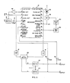
- the error signal disabling or killing circuit is implemented in the novel manner shown.
- the output from the "third terminal", terminal 5 of the IC, on which an error signal appears is coupled to one terminal of a 100 uF capacitor 12', the other terminal of the 100 uF capacitor 12' being connected to the output of an electronic switch 14', whose input is connected to the output of a low output impedance operational amplifier 46.
- the input of the operational amplifier 46 is connected to the "first terminal", namely terminal 2 of the IC, at which the output of the envelope detector normally appears.
- the low output impedance of the operational amplifier 14 effectively suppresses or kills and error signal present at terminal 5 (generated within the IC) and, at the same time, also controls the inverse modulation process which occurs within the IC, so that no additional inverse modulator is required external to the IC.
Landscapes
- Engineering & Computer Science (AREA)
- Signal Processing (AREA)
- Computer Networks & Wireless Communication (AREA)
- Stereo-Broadcasting Methods (AREA)
Applications Claiming Priority (2)
| Application Number | Priority Date | Filing Date | Title |
|---|---|---|---|
| US770170 | 1985-08-28 | ||
| US06/770,170 US4641341A (en) | 1985-08-28 | 1985-08-28 | Automatic multi-system AM stereo receiver using existing single-system AM stereo decoder IC |
Publications (3)
| Publication Number | Publication Date |
|---|---|
| EP0214726A2 true EP0214726A2 (fr) | 1987-03-18 |
| EP0214726A3 EP0214726A3 (en) | 1987-07-01 |
| EP0214726B1 EP0214726B1 (fr) | 1991-09-11 |
Family
ID=25087696
Family Applications (1)
| Application Number | Title | Priority Date | Filing Date |
|---|---|---|---|
| EP86305451A Expired - Lifetime EP0214726B1 (fr) | 1985-08-28 | 1986-07-16 | Récepteur automatique stéréophonique à modulation d'amplitude multisystème utilisant un circuit intégré décodeur stéréophonique à modulation d'amplitude à système unique déjà existant |
Country Status (11)
| Country | Link |
|---|---|
| US (1) | US4641341A (fr) |
| EP (1) | EP0214726B1 (fr) |
| JP (1) | JPS6251323A (fr) |
| KR (1) | KR870002704A (fr) |
| AU (1) | AU584222B2 (fr) |
| BR (1) | BR8604105A (fr) |
| CA (1) | CA1237478A (fr) |
| DE (1) | DE3681385D1 (fr) |
| IN (1) | IN163378B (fr) |
| MX (1) | MX165077B (fr) |
| NZ (1) | NZ216753A (fr) |
Families Citing this family (6)
| Publication number | Priority date | Publication date | Assignee | Title |
|---|---|---|---|---|
| EP0318617B1 (fr) * | 1987-12-04 | 1993-08-04 | Hazeltine Corporation | Appareil de traitement de signaux stéréophoniques et récepteurs universels AM stéréo contenant un tel appareil |
| US5008939A (en) * | 1989-07-28 | 1991-04-16 | Bose Corporation | AM noise reducing |
| US5023909A (en) * | 1989-09-25 | 1991-06-11 | Kahn Leonard R | Multi-system AM stereo receiver having preferred mode of operation |
| DE69228624T2 (de) | 1991-04-18 | 1999-07-29 | Bose Corp., Framingham, Mass. | Reduktion von hörbaren Rauschen bei Stereo-Empfang |
| US7006883B2 (en) * | 2001-10-10 | 2006-02-28 | Semiconductor Energy Laboratory Co., Ltd. | Production system for composite product and production method for manufacturing of same |
| US20060004567A1 (en) * | 2002-11-27 | 2006-01-05 | Visual Pronunciation Software Limited | Method, system and software for teaching pronunciation |
Citations (2)
| Publication number | Priority date | Publication date | Assignee | Title |
|---|---|---|---|---|
| FR2512295A1 (fr) | 1981-08-31 | 1983-03-04 | Kahn Leonard | Recepteur stereophonique a modulation d'amplitude multi-systeme |
| US4535470A (en) | 1982-05-27 | 1985-08-13 | Sony Corporation | AM stereo decoder for multiple coding systems |
Family Cites Families (6)
| Publication number | Priority date | Publication date | Assignee | Title |
|---|---|---|---|---|
| JPS5929855B2 (ja) * | 1978-04-05 | 1984-07-24 | 富士写真フイルム株式会社 | カラ−写真感光材料 |
| US4368356A (en) * | 1981-03-20 | 1983-01-11 | Motorola Inc. | Pilot tone detector utilizing phase deviation signals |
| US4420658A (en) * | 1981-05-04 | 1983-12-13 | Hazeltine Corporation | Multiple tone signal system |
| JPS58206249A (ja) * | 1982-05-27 | 1983-12-01 | Sony Corp | Amステレオ受信機 |
| JPS59140739A (ja) * | 1983-01-31 | 1984-08-13 | Sony Corp | Amステレオ受信機のパイロット信号検出回路 |
| US4536885A (en) * | 1983-03-03 | 1985-08-20 | Hazeltine Corporation | Distortion correcting AM stereo receiver with non-flat AGC |
-
1985
- 1985-08-28 US US06/770,170 patent/US4641341A/en not_active Expired - Fee Related
-
1986
- 1986-07-04 NZ NZ216753A patent/NZ216753A/xx unknown
- 1986-07-09 CA CA000513387A patent/CA1237478A/fr not_active Expired
- 1986-07-11 AU AU60087/86A patent/AU584222B2/en not_active Ceased
- 1986-07-16 EP EP86305451A patent/EP0214726B1/fr not_active Expired - Lifetime
- 1986-07-16 DE DE8686305451T patent/DE3681385D1/de not_active Expired - Lifetime
- 1986-07-28 IN IN568/CAL/86A patent/IN163378B/en unknown
- 1986-08-13 JP JP61190402A patent/JPS6251323A/ja active Pending
- 1986-08-28 MX MX3574A patent/MX165077B/es unknown
- 1986-08-28 KR KR1019860007164A patent/KR870002704A/ko not_active Application Discontinuation
- 1986-08-28 BR BR8604105A patent/BR8604105A/pt unknown
Patent Citations (2)
| Publication number | Priority date | Publication date | Assignee | Title |
|---|---|---|---|---|
| FR2512295A1 (fr) | 1981-08-31 | 1983-03-04 | Kahn Leonard | Recepteur stereophonique a modulation d'amplitude multi-systeme |
| US4535470A (en) | 1982-05-27 | 1985-08-13 | Sony Corporation | AM stereo decoder for multiple coding systems |
Also Published As
| Publication number | Publication date |
|---|---|
| JPS6251323A (ja) | 1987-03-06 |
| NZ216753A (en) | 1989-09-27 |
| CA1237478A (fr) | 1988-05-31 |
| EP0214726A3 (en) | 1987-07-01 |
| DE3681385D1 (de) | 1991-10-17 |
| BR8604105A (pt) | 1987-04-22 |
| MX165077B (es) | 1992-10-21 |
| US4641341A (en) | 1987-02-03 |
| IN163378B (fr) | 1988-09-17 |
| AU584222B2 (en) | 1989-05-18 |
| EP0214726B1 (fr) | 1991-09-11 |
| KR870002704A (ko) | 1987-04-06 |
| AU6008786A (en) | 1987-03-05 |
Similar Documents
| Publication | Publication Date | Title |
|---|---|---|
| US4534054A (en) | Signaling system for FM transmission systems | |
| US4602381A (en) | Adaptive expanders for FM stereophonic broadcasting system utilizing companding of difference signal | |
| US5507024A (en) | FM data-system radio receiver | |
| US4688255A (en) | Compatible AM broadcast/data transmisison system | |
| US6418300B1 (en) | Method and device for transmitting mixed analog and digital signals by the same transmitter | |
| EP0418036B1 (fr) | Réduction du bruit audible | |
| US4159398A (en) | Stereo presence signal for an AM stereo system | |
| NO782914L (no) | Mottaker for kompatible am stereo-signaler | |
| EP0214726B1 (fr) | Récepteur automatique stéréophonique à modulation d'amplitude multisystème utilisant un circuit intégré décodeur stéréophonique à modulation d'amplitude à système unique déjà existant | |
| EP0231616B1 (fr) | Récepteur stéréophonique AM avec protection contre le mouvement de l'image stéréo | |
| US5023909A (en) | Multi-system AM stereo receiver having preferred mode of operation | |
| US4580284A (en) | Pilot tone cancelling circuit for AM stereo decoder | |
| US5666660A (en) | System for receiving a radio signal including multiple receiving units | |
| KR910003418B1 (ko) | Am스테레오 수신기 | |
| CA1154096A (fr) | Recepteur de signaux multiplex | |
| CA1334208C (fr) | Dispositif de traitement de signaux stereo et recepteurs am stereo incorporant ce dispositif | |
| EP0304147B1 (fr) | Transmetteur comportant des moyen pour contrôler la radiaton de fréquences hors bande | |
| US4477924A (en) | AM Stereo detector | |
| US5740519A (en) | Method for the time-correlated transmission of a control signal and a radio program signal | |
| US4490837A (en) | AM Stereo to FM stereo converter | |
| EP0318617B1 (fr) | Appareil de traitement de signaux stéréophoniques et récepteurs universels AM stéréo contenant un tel appareil | |
| KR820001531B1 (ko) | 무선방송 시스템용 수신기 | |
| KR820001333B1 (ko) | 양립식 am스테레오 신호수신기 | |
| CA1263149A (fr) | Systeme compatible de diffusion am et de transmission de donnees | |
| EP0420584A2 (fr) | Circuit PLL démodulateur dans un récepteur d'informations de trafic |
Legal Events
| Date | Code | Title | Description |
|---|---|---|---|
| PUAI | Public reference made under article 153(3) epc to a published international application that has entered the european phase |
Free format text: ORIGINAL CODE: 0009012 |
|
| AK | Designated contracting states |
Kind code of ref document: A2 Designated state(s): DE FR GB IT NL |
|
| PUAL | Search report despatched |
Free format text: ORIGINAL CODE: 0009013 |
|
| AK | Designated contracting states |
Kind code of ref document: A3 Designated state(s): DE FR GB IT NL |
|
| 17P | Request for examination filed |
Effective date: 19871201 |
|
| 17Q | First examination report despatched |
Effective date: 19900320 |
|
| GRAA | (expected) grant |
Free format text: ORIGINAL CODE: 0009210 |
|
| AK | Designated contracting states |
Kind code of ref document: B1 Designated state(s): DE FR GB IT NL |
|
| ITF | It: translation for a ep patent filed | ||
| REF | Corresponds to: |
Ref document number: 3681385 Country of ref document: DE Date of ref document: 19911017 |
|
| ET | Fr: translation filed | ||
| PLBE | No opposition filed within time limit |
Free format text: ORIGINAL CODE: 0009261 |
|
| STAA | Information on the status of an ep patent application or granted ep patent |
Free format text: STATUS: NO OPPOSITION FILED WITHIN TIME LIMIT |
|
| 26N | No opposition filed | ||
| PGFP | Annual fee paid to national office [announced via postgrant information from national office to epo] |
Ref country code: FR Payment date: 19940615 Year of fee payment: 9 |
|
| PGFP | Annual fee paid to national office [announced via postgrant information from national office to epo] |
Ref country code: GB Payment date: 19940627 Year of fee payment: 9 |
|
| PGFP | Annual fee paid to national office [announced via postgrant information from national office to epo] |
Ref country code: NL Payment date: 19940731 Year of fee payment: 9 |
|
| PGFP | Annual fee paid to national office [announced via postgrant information from national office to epo] |
Ref country code: DE Payment date: 19940930 Year of fee payment: 9 |
|
| PG25 | Lapsed in a contracting state [announced via postgrant information from national office to epo] |
Ref country code: GB Effective date: 19950716 |
|
| PG25 | Lapsed in a contracting state [announced via postgrant information from national office to epo] |
Ref country code: NL Effective date: 19960201 |
|
| GBPC | Gb: european patent ceased through non-payment of renewal fee |
Effective date: 19950716 |
|
| NLV4 | Nl: lapsed or anulled due to non-payment of the annual fee |
Effective date: 19960201 |
|
| PG25 | Lapsed in a contracting state [announced via postgrant information from national office to epo] |
Ref country code: DE Effective date: 19960402 |
|
| PG25 | Lapsed in a contracting state [announced via postgrant information from national office to epo] |
Ref country code: FR Effective date: 19960430 |
|
| REG | Reference to a national code |
Ref country code: FR Ref legal event code: ST |
|
| REG | Reference to a national code |
Ref country code: FR Ref legal event code: ST |
|
| REG | Reference to a national code |
Ref country code: FR Ref legal event code: ST |
|
| PG25 | Lapsed in a contracting state [announced via postgrant information from national office to epo] |
Ref country code: IT Free format text: LAPSE BECAUSE OF NON-PAYMENT OF DUE FEES;WARNING: LAPSES OF ITALIAN PATENTS WITH EFFECTIVE DATE BEFORE 2007 MAY HAVE OCCURRED AT ANY TIME BEFORE 2007. THE CORRECT EFFECTIVE DATE MAY BE DIFFERENT FROM THE ONE RECORDED. Effective date: 20050716 |