EP0214497B1 - Line protection switch equipment - Google Patents
Line protection switch equipment Download PDFInfo
- Publication number
- EP0214497B1 EP0214497B1 EP86111279A EP86111279A EP0214497B1 EP 0214497 B1 EP0214497 B1 EP 0214497B1 EP 86111279 A EP86111279 A EP 86111279A EP 86111279 A EP86111279 A EP 86111279A EP 0214497 B1 EP0214497 B1 EP 0214497B1
- Authority
- EP
- European Patent Office
- Prior art keywords
- line
- input
- output
- terminal
- protection
- Prior art date
- Legal status (The legal status is an assumption and is not a legal conclusion. Google has not performed a legal analysis and makes no representation as to the accuracy of the status listed.)
- Expired
Links
Images


Classifications
-
- H—ELECTRICITY
- H04—ELECTRIC COMMUNICATION TECHNIQUE
- H04B—TRANSMISSION
- H04B1/00—Details of transmission systems, not covered by a single one of groups H04B3/00 - H04B13/00; Details of transmission systems not characterised by the medium used for transmission
- H04B1/74—Details of transmission systems, not covered by a single one of groups H04B3/00 - H04B13/00; Details of transmission systems not characterised by the medium used for transmission for increasing reliability, e.g. using redundant or spare channels or apparatus
Definitions
- the present invention relates to a line protection switch equipment in a communication system, for switching from a working line (i.e., a normal line) to a protection line (i.e., a standby line) to continue communication when a fault occurs on the working line.
- a working line i.e., a normal line
- a protection line i.e., a standby line
- a one to one or n to one working-protection switching system is employed for continuing the communication by separating the faulty portion and by switching to a protection equipment or to a protection line.
- the switching circuit for switching and connecting the faulty line among the working n lines and one protection line must be maintained in the switching state even when the power is cut, and should have a simple construction.
- the switching circuit must not be formed by a matrix switch.
- the protection line is previously determined.
- the switching and connection are carried out by changing the faulty working line to a protection line and by making the protection line a working line.
- the working line which became the protection line is switched to again become working line, and the protection line which became the working line is switched to again become a protection line.
- the protection line is previously determined. Therefore, a disadvantage arises in that there is little freedom of line selection.
- a floating (or quasi-fixed) system is known.
- the working-protection switching can be carried out without specifically determining a protection line so that the freedom of line selection is increased.
- the switching circuit has a matrix switch construction. Further, since a high speed data switching of several ten to several hundred mega bit/s must be effected in accordance with the degree of multiplication, the switching circuit cannot be realized by a simple contact construction. Therefore, the circuit having a matrix switch construction has a disadvantage of being large in scale.
- the object of the present invention is to provide a new quasi-fixed protection system which is adaptable by using a switching circuit having a relatively simple construction.
- a line protection switch equipment in a communication system connected between a plurality of lines, one of the lines being operatively used as a protection line, and the other of the lines being operatively used as a working line.
- the line protection switch equipment comprises: a plurality of two-input and two-output switches, respectively connected between the lines, and a loop line for connecting the two-input and two-output switches to each other in series, forming a loop; each of the two-input and two-output switches having a first input terminal, a second inputterminal, a firstoutputterminal and a second output terminal.
- the first input terminal and the first output terminal are connected to a corresponding one of the lines, and the second input terminal and the second output terminal are connected to the loop line; whereby, by switching the two-input and two-output switches corresponding to a faulty working line and to the protection line, the faulty working line is switched to become a protection line, and the protection line becomes a working line.
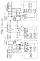
- FIG. 1 is a block diagram illustrating a data transmission system of a prior art disclosed in the previously mentioned reference (FUJITSU Sci. Tech.).
- the system shown in Fig. 1 includes line protection switch equipment (LPSW) 1 and 2, control portions 3 and 4, and line terminal equipment (LTE) 5 and 6, which are connected via 3R type regenerator (REG) 8 controlled by a control portion 9.
- the line terminal equipment 5 and 6 includes normal (NOR) equipment and standby (STBY) equipment.
- the control portions 3 and 4 include master (MSV) and slave (SSV) supervisory equipment, bit error rate monitoring (BER MON) equipment, order wire (OW) equipment, and SV/OW interface (INF) equipment.
- the control portion 9 also includes BER MON equipment, SSV equipment, OW equipment, and SV/OW INF equipment.
- the present invention relates to the construction of the line protection switch equipment (LPSW) 1 or 2.
- LPSW line protection switch equipment
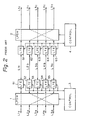
- FIG. 2 is a simplified block diagram of Fig. 1.
- the line protection switch equipment (LPSW) 1 is connected between lines L 1a ⁇ L 5a and line terminal equipment (LTE) 51-55.
- the line terminal equipment (LTE) 51-55 and 61-65 are connected via lines L 1b ⁇ L 5b .
- the line protection switch equipment (LPSW) 2 is connected between the line terminal equipment (LTE) 61-65 and lines L 1c ⁇ L 5c .
- the control portions 3 and 4 supervise the state of the line terminal equipment (LTE) 51-55 and 61-65 and control the path in the line protection switch equipment (LPSW) 1 and 2.
- the lines L 1a ⁇ L 5a , L 1b ⁇ L 5b and L 1c ⁇ L 5c conduct a high-speed multi-transmission of, for example, 405 mega bit/s, and are constructed by coaxial cables or optical fibers.
- electrical-optical converting elements such as semiconductor lasers and optical-electrical converting elements such as avalanche photodiodes (APD) are provided in the line terminal equipment 51-55 and 61-65.
- the lines L 1a ⁇ L 4a , L 1b ⁇ L 4b , and L 1c ⁇ L 4c are predetermined as working lines, and the lines L 5a , L Sb and L 5c are predetermined as protection lines.
- the line protection switch equipment (LPSW) 1 usually connects the lines L 1a ⁇ L 5a to the corresponding line terminal equipment 51-55.
- the control portions 3 and 4 respectively receive control information from the line terminal equipment (LTE) 52 and 62 so that, as illustrated by dotted lines, the line protection switch equipment (LPSW) 1 and 2 make a path between the protection lines L sa and L 5c via the faulty working line L 2b and simultaneously between the working lines L 2a and L 2c via the protection line L 5b . Then, the control portions 3 and 4 determine whether the fault has been recovered on the line L 2b , which has been made a protection line. When the recovery of the fault is detected, control information is transmitted and received between the control portions 3 and 4 so that the line protection switch equipment 1 and 2 switches to the original connecting state, whereby the line L Sb again becomes the protection line and the line L 2b again becomes the working line.
- LTE line terminal equipment
- LPSW line protection switch equipment
- the protection line is previously determined and therefore, there is little freedom of line selection.
- a floating protection system is known in which a protection line is not previously determined but any line can be determined as a protection line during operation.
- switching between a working line and a protection line can be carried out without specifically determining a protection line so that the freedom of line selection is increased.
- the line protection switch equipment in the floating protection system must comprise matrix switch which is very complicated.
- the line protection switch equipment having the matrix construction cannot be realized by a simple contact construction. Therefore the matrix switch construction has a disadvantage of being large in scale.
- FIG. 3A is a block diagram of a line protection switch equipment (LPSW) developed before the creation of the present invention.
- LPSW line protection switch equipment
- the LPSW shown in Fig. 3A includes a plurality of two-input and two-output switches SW 1 , SW2, ... SW (n-1) , SW " and SW (n+1) each having a first input terminal 1 1 , a second input terminal 1 2 , a first output terminal 0 1 , and a second output terminal O2, as shown in Figs. 3B and 3C.
- the line L (n+1)a or L (n+1)b is predetermined to be a protection line.
- the other lines L 1a , L 2a , ... and L na , and L 1b , L 2b , ..., and L nb are predetermined as working lines.
- the lines L (n+1)a and L (n+1)b are predetermined as protection lines.
- the state of the switches SW n and SW (n+1) is changed so that the first input terminal 1 1 is connected to the second output terminal 0 2 , and the second input terminal l 2 is connected to the first output terminal 0 1 , as shown in Figs. 3A and 3C.
- the working line L na is connected through the switches SW n , SW n-1 , ..., SW 1 and SW (n+1) to the protection line L (n+1)b .
- the LPSW shown in Fig. 3A has a disadvantage in that there is little flexibility in the selection of the protection line, since the protection line L (n+1)a or L (n+1)b is previously determined. Further, if a line connecting adjacent switches is disconnected, the line protection switch equipment becomes inoperative.
- the object of the present invention is to provide a new floating system adaptable in a communication system by using a line protection switch equipment having a relatively simple construction.
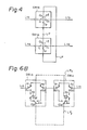
- the line protection switch equipment LPSW according to the present invention is provided in a communication system.
- the LPSW in Fig. 4 is connected in series with lines L 1a and L 1b , ..., and L na and L nb .
- One of the lines L 1b , ..., and L nb is operatively used as a protection line.
- the other lines L 2b (not shown), ..., and L nb are operatively used as working lines.
- Each switch SW ia has a first input terminal 1 1 , a second input terminal 1 2 , a first output terminal 0 1 and a second output terminal 0 2 .
- the first input terminal 1 1 and the first output terminal O 1 are respectively connected to the corresponding lines L ia and L ib .
- the second input terminal 1 2 and the second output terminal 0 2 are connected to the loop line LP.
- the faulty working line is switched to become a protection line.
- any one of the lines L 1b , ..., and L nb can be made a protection line.
- the line L 1b is a working line
- the line L nb is a protection line. Then, when a fault occurs on the working line L 1b , if the relay contacts r1 are switched as illustrated by dotted lines, the line L 1a is connected, via the terminals 1 1 and O 2 of the switch SW 1a , the loop line LP and the terminals 1 2 and 0 1 , to the line L nb .
- the line L nb which was a protection line, becomes a working line, and the line L na is connected, via the terminals 1 1 and 0 2 , the loop line LP, and the terminals 1 2 and O 1 , to the line L 1b'
- the line L 1b becomes a protection line.
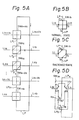
- FIG. 5A shows a first embodiment of the present invention.
- the circuit structure shown in Fig. 5A is substantially the same as the circuit shown in Fig. 4.
- the LPSW shown in Fig. 5A includes a plurality of two-input and two-output switches SW 1a , SW 2a , ..., SW (n-1) a, SW na and SW (n+1)a ⁇
- a loop line LP connects the switches SW (n+1)a , SW 1a , SW 2a , ..., and SW na in series.
- Fig. 5B shows a normal state of a two-input and two-output switch SW ia in the LPSW shown in Fig. 5A; and Fig. 5C shows a switched state of the switch SW ia .
- the first input terminal 1 1 is connected to the first output terminal O 1 ; and the second input terminal 1 2 is connected to the second output terminal 0 2 .
- the switched state shown in Fig. 5C the first input terminal 1 1 is connected to the second output terminal O2; and the second input terminal 1 2 is connected to the first output terminal O 1 .
- any line in the lines L 1b , L 2b , ..., and L nb can be arbitrarily switched from being a working line to being a protection line, when the protection line L (n+1)b is switched from being a protection line to being a working line, in the same way as described with reference to Fig. 4. Accordingly, the flexibility in the selection of a protection line is increased in comparison with the LPSW created before the present invention, as shown in Fig. 3A.
- Each of the two-input and two-output switches SW 1a ⁇ SW (n+1)a is constructed by a relay in which the contacts are self-latched by residual magnetism, maintaining the normal state or the switched state even after the power is cut off. Also, transfer contacts are employed as the relay contacts.
- FIG. 5D is a circuit diagram of the two-input and two-output switch SW ia in the LPSW shown in Fig. 5A.
- the switch SW ia includes transfer contacts a1 ⁇ a4 of a self-latching type relay (not shown).
- the illustrated state shows the normal state shown in Fig. 5B in which the opposing terminals 1 1 and O 1 , and 1 2 and 0 2 are connected. Therefore, the lines L ia and L ib are connected via the transfer contacts a1 and a2, and the loop lines LP are connected via the transfer contacts a3 and a4.
- the line L ia is connected to the upper loop line LP u via the transfer contacts a1 and a3; and the line L ib is connected to the lower loop line LP l via the transfer contacts a3 and a4, resulting in the switched state illustrated in Fig. 5C.
- FIG. 6A shows a second embodiment of a line protection switch equipment according to the present invention.
- the loop line LP connects the switches SW (n+1)b' SW 1b , SW 2b , ... and SW nb in series, and connects the switches SW (n+1)c , SW 1c , SW 2c , ..., and SW nc in series.
- the loop line LP also connects the switches SW (n+1)b and SW (n+1)c in series, and connects the switches SW nc and SW nb in series.
- the second output terminal 0 2 of a switch SW ib is connected to the second input terminal of the adjacent switch SW (i-1)b ; and the second output terminal O 2 of a switch SW jc is connected to the second input terminal l 2 of a switch SW (j+1)c , where i and j are 1, 2, ..., or n.
- the second output terminal O2 of the switch SW 1b is connected to the second input terminal 1 2 of the switch SW (n+1)b .
- the second output terminal O 2 of the switch SW (n+1)c is connected to the second input terminal l 2 of the switch SW 1c .
- the lines L 1a and L 1b are protection lines; and that the lines L 2a and L 2b are working lines.
- the protection lines L 1a and L 1b are connected by the switches SW 1b and SW 1c ; and the working lines L 2a and L 2b are connected by the switches SW 2b and SW 2c .
- the states of the switches SW 2b , SW 1c and SW 2c are changed from the normal state (see Fig. 5B) to the switched state (see Fig. 5C) as illustrated in Fig. 6A by solid lines.
- a signal on the working line L 2a is transmitted, through the switches SW 2b , the loop line LP 2 , the switch SW 1b , the loop line LP 1 , switch ⁇ SW (n+1)b , the loop line LP, the switch SW (n+1)c , the loop LP 1a , and the switch SW 1c , to the protection line L 1b which is now a working line.
- a signal on the protection line L 1a is transmitted, through the switches SW 1b' SW 1c and SW 2c , to the working line L 2b which is now a protection line. Accordingly, the signal path in the LPSW in Fig. 6A is shorter than the signal path in the LPSW in Fig. 5A.
- Figure 6B shows the two-input and two-output switches SW 1b and SW ic in the afore-mentioned second embodiment, in which the two-input and two-output switches SW ib and SW, c respectively have transfer contacts a1 ⁇ a4 and b1-b4 of a self-latching type relay (not shown).
- the illustrated state is a normal state in which the opposing terminals 1 1 and 0 1 , and 1 2 and 0 2 are connected so that the lines L ia and L ib are connected, and the loop line LP is electrically separated from the lines L ia and L ib'
- the transfer contacts a1 ⁇ a4 are switched from the illustrated state so that the adjacent terminals 1 1 and 0 2 , and 1 2 and 0 1 are connected.
- the line L ia is connected to the upper loop line LP u
- the line between the switches SW ic and SW ib is connected to the lower loop line LP I .
- the second embodiment shown in Fig. 6A has an advantage of short signal path as described before, it has a large scale circuit because twice the number of switches must be provided compared to the number of switches in the first embodiment shown in Fig. 5A.
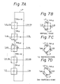
- Figure 7A shows a third embodiment of a line protection switch equipment according to the present invention.
- Figures 7B to 7D respectively show switching states of a two-input and two-output switch SW id .
- the only difference between the first embodiment shown in Fig. 5A and the third embodiment shown in Fig. 7A is that the switch SW id in Fig. 7A has, in addition to the first switched state shown in Fig. 7C which is the same as switched state of Fig. 5C, a second switched state as shown in Fig. 7D.
- the first input terminal l 1 is connected to the second input terminal 1 2
- the first output terminal 0 1 is connected to the second output terminal 0 2 .
- the signal path in this third embodiment is very short.
- the number of switches in the third embodiment is half that of the switches in the second embodiment.
- FIG. 7E is a circuit diagram of the two-input and two-output switch SW id in the LPSW shown in Fig. 7A.
- the switch SW ;d includes transfer contacts a1 ⁇ a8 of a self-latching type relay (not shown).
- the illustrated state shows the normal state shown in Fig. 7B in which the opposing terminals 1 1 and 0 1 , and 1 2 and 0 2 are connected. Therefore, the lines L ia and L ib are connected via the transfer contacts a1 and a2, and the loop lines LP are connected via the transfer contacts a3 and a4.
- the line L ia is connected to the upper loop line LP via the transfer contacts a1, a5, a6 and a3; and the line L ib is connected to the lower loop line LP via the transfer contacts a2, a7, a8 and a4, resulting in the switched state illustrated in Fig. 7C.
- the line L ia is connected to the lower loop line LP, via the transfer contacts a1, a5, a8 and a4; and the line L ib is connected to the upper loop line LP u via the transfer contacts a2, a7, a6 and a3, resulting in the switched state illustrated in Fig. 7D.
- the lines L ia and L ib can be connected to either one of the upper loop line LP u and lower loop line LP l .
Landscapes
- Engineering & Computer Science (AREA)
- Computer Networks & Wireless Communication (AREA)
- Signal Processing (AREA)
- Small-Scale Networks (AREA)
- Detection And Prevention Of Errors In Transmission (AREA)
Applications Claiming Priority (2)
| Application Number | Priority Date | Filing Date | Title |
|---|---|---|---|
| JP60179452A JPS6239921A (ja) | 1985-08-16 | 1985-08-16 | 回線切換装置 |
| JP179452/85 | 1985-08-16 |
Publications (3)
| Publication Number | Publication Date |
|---|---|
| EP0214497A2 EP0214497A2 (en) | 1987-03-18 |
| EP0214497A3 EP0214497A3 (en) | 1988-07-13 |
| EP0214497B1 true EP0214497B1 (en) | 1990-11-28 |
Family
ID=16066104
Family Applications (1)
| Application Number | Title | Priority Date | Filing Date |
|---|---|---|---|
| EP86111279A Expired EP0214497B1 (en) | 1985-08-16 | 1986-08-14 | Line protection switch equipment |
Country Status (9)
| Country | Link |
|---|---|
| US (1) | US4733320A (cg-RX-API-DMAC7.html) |
| EP (1) | EP0214497B1 (cg-RX-API-DMAC7.html) |
| JP (1) | JPS6239921A (cg-RX-API-DMAC7.html) |
| AU (1) | AU572735B2 (cg-RX-API-DMAC7.html) |
| CA (1) | CA1287098C (cg-RX-API-DMAC7.html) |
| DE (1) | DE3675856D1 (cg-RX-API-DMAC7.html) |
| HK (1) | HK56492A (cg-RX-API-DMAC7.html) |
| NZ (1) | NZ217150A (cg-RX-API-DMAC7.html) |
| SG (1) | SG46192G (cg-RX-API-DMAC7.html) |
Families Citing this family (8)
| Publication number | Priority date | Publication date | Assignee | Title |
|---|---|---|---|---|
| GB8813958D0 (en) * | 1988-06-13 | 1988-07-20 | Plessey Telecomm | Data path protection |
| JP3023705B2 (ja) * | 1990-12-20 | 2000-03-21 | 富士通株式会社 | 予備チャンネル切替え装置および方法 |
| JPH0786988A (ja) * | 1993-09-16 | 1995-03-31 | Fujitsu Ltd | Pca伝送装置及びpca伝送方法 |
| US5594581A (en) * | 1993-12-29 | 1997-01-14 | Lucent Technologies Inc. | Low loss optical transmission/monitoring path selection in redundant equipment terminals |
| JPH07264156A (ja) * | 1994-03-18 | 1995-10-13 | Fujitsu Ltd | 同期通信網の障害検出方式 |
| KR100301575B1 (ko) * | 1995-12-22 | 2001-11-22 | 박종섭 | 신호 전송장치 |
| US7266841B2 (en) * | 2000-12-22 | 2007-09-04 | Tyco Electronics Corporation | Security and communications module |
| EP2626002A4 (en) * | 2010-10-08 | 2015-09-30 | Olympus Medical Systems Corp | IMAGING DEVICE |
Family Cites Families (6)
| Publication number | Priority date | Publication date | Assignee | Title |
|---|---|---|---|---|
| US3576951A (en) * | 1967-12-09 | 1971-05-04 | Nippon Electric Co | Calling subscriber identification system |
| US3864533A (en) * | 1973-06-01 | 1975-02-04 | Vidar Corp | Automatic line transfer system and method for a communications system |
| US4061989A (en) * | 1975-09-02 | 1977-12-06 | Trw Inc. | Redundancy switching system |
| US4007339A (en) * | 1975-11-28 | 1977-02-08 | Bell Telephone Laboratories, Incorporated | Arrangement serving operator assistance calls requiring routing back to originating offices |
| DE3360779D1 (de) * | 1982-06-30 | 1985-10-17 | Bbc Brown Boveri & Cie | Installation de commutation |
| JPS6038950A (ja) * | 1983-08-11 | 1985-02-28 | Sumitomo Electric Ind Ltd | 伝送路制御方式 |
-
1985
- 1985-08-16 JP JP60179452A patent/JPS6239921A/ja active Granted
-
1986
- 1986-08-07 CA CA000515537A patent/CA1287098C/en not_active Expired - Lifetime
- 1986-08-08 NZ NZ217150A patent/NZ217150A/xx unknown
- 1986-08-11 AU AU61065/86A patent/AU572735B2/en not_active Ceased
- 1986-08-14 EP EP86111279A patent/EP0214497B1/en not_active Expired
- 1986-08-14 DE DE8686111279T patent/DE3675856D1/de not_active Expired - Lifetime
- 1986-08-15 US US06/896,954 patent/US4733320A/en not_active Expired - Lifetime
-
1992
- 1992-04-24 SG SG46192A patent/SG46192G/en unknown
- 1992-07-30 HK HK564/92A patent/HK56492A/xx unknown
Also Published As
| Publication number | Publication date |
|---|---|
| NZ217150A (en) | 1989-08-29 |
| JPS6239921A (ja) | 1987-02-20 |
| AU572735B2 (en) | 1988-05-12 |
| CA1287098C (en) | 1991-07-30 |
| SG46192G (en) | 1992-06-12 |
| HK56492A (en) | 1992-08-07 |
| US4733320A (en) | 1988-03-22 |
| AU6106586A (en) | 1987-02-19 |
| EP0214497A3 (en) | 1988-07-13 |
| DE3675856D1 (de) | 1991-01-10 |
| EP0214497A2 (en) | 1987-03-18 |
| JPH0317417B2 (cg-RX-API-DMAC7.html) | 1991-03-08 |
Similar Documents
| Publication | Publication Date | Title |
|---|---|---|
| US5717796A (en) | Optical fiber transmission system utilizing a line switched ring to provide protection | |
| US4853927A (en) | Method and circuit arrangement for decentralized controlled transmission rerouting | |
| US6697546B2 (en) | Optical node system and switched connection method | |
| EP0347903A3 (en) | High-speed optical packet switching system using optical buffer between incoming and outgoing channels | |
| US4347605A (en) | Multiplexed telecommunication systems | |
| EP0533167B1 (en) | Optical communication system having transmission line switching system | |
| EP0214497B1 (en) | Line protection switch equipment | |
| EP0332199B1 (en) | Transmission line switching system | |
| US4775210A (en) | Voice and data distribution system with fiber optic multinode star network | |
| US7327960B1 (en) | Receiver transponder for protected networks | |
| EP0032992B1 (en) | Circuit for interfacing a half-duplex digital data line with a simplex transmitting and a simplex receiving line, and vice-versa | |
| US5533006A (en) | Control system for a ring type network system | |
| EP1014613A2 (en) | Shared optical protection in an optical communications network | |
| US5648963A (en) | Input and output side conversion interfaces for an ATM exchange | |
| US4961180A (en) | Arrangements for producing and recognizing information identifying non-occupied transmission paths in a digital transmission system | |
| US5594581A (en) | Low loss optical transmission/monitoring path selection in redundant equipment terminals | |
| KR100334907B1 (ko) | 파장분할다중 광전송시스템에서 광채널계층의 단방향절체장치 | |
| CN1059768C (zh) | 双重连接 | |
| JPS63221725A (ja) | 光伝送方式 | |
| CA2173947C (en) | Multiplexing/demultiplexing unit arranged on a multi-surface integrated circuit | |
| JPH04334135A (ja) | 光ファイバプロテクション方式 | |
| EP0889665B1 (en) | Optical crossconnect apparatus and optical transmission system | |
| KR20020078165A (ko) | 통신시스템의 최적화 정보 전송장치 | |
| EP1429483B1 (en) | Signaling of defects for HW supported protection switching inside an optical cross-connected system | |
| JPS6357971B2 (cg-RX-API-DMAC7.html) |
Legal Events
| Date | Code | Title | Description |
|---|---|---|---|
| PUAI | Public reference made under article 153(3) epc to a published international application that has entered the european phase |
Free format text: ORIGINAL CODE: 0009012 |
|
| AK | Designated contracting states |
Kind code of ref document: A2 Designated state(s): DE FR GB SE |
|
| PUAL | Search report despatched |
Free format text: ORIGINAL CODE: 0009013 |
|
| AK | Designated contracting states |
Kind code of ref document: A3 Designated state(s): DE FR GB SE |
|
| 17P | Request for examination filed |
Effective date: 19881129 |
|
| 17Q | First examination report despatched |
Effective date: 19891002 |
|
| GRAA | (expected) grant |
Free format text: ORIGINAL CODE: 0009210 |
|
| AK | Designated contracting states |
Kind code of ref document: B1 Designated state(s): DE FR GB SE |
|
| ET | Fr: translation filed | ||
| REF | Corresponds to: |
Ref document number: 3675856 Country of ref document: DE Date of ref document: 19910110 |
|
| PLBE | No opposition filed within time limit |
Free format text: ORIGINAL CODE: 0009261 |
|
| STAA | Information on the status of an ep patent application or granted ep patent |
Free format text: STATUS: NO OPPOSITION FILED WITHIN TIME LIMIT |
|
| 26N | No opposition filed | ||
| PGFP | Annual fee paid to national office [announced via postgrant information from national office to epo] |
Ref country code: GB Payment date: 19920602 Year of fee payment: 7 |
|
| PGFP | Annual fee paid to national office [announced via postgrant information from national office to epo] |
Ref country code: SE Payment date: 19920630 Year of fee payment: 7 |
|
| PGFP | Annual fee paid to national office [announced via postgrant information from national office to epo] |
Ref country code: FR Payment date: 19920828 Year of fee payment: 7 Ref country code: DE Payment date: 19920828 Year of fee payment: 7 |
|
| PG25 | Lapsed in a contracting state [announced via postgrant information from national office to epo] |
Ref country code: GB Effective date: 19930814 |
|
| PG25 | Lapsed in a contracting state [announced via postgrant information from national office to epo] |
Ref country code: SE Effective date: 19930815 |
|
| GBPC | Gb: european patent ceased through non-payment of renewal fee |
Effective date: 19930814 |
|
| PG25 | Lapsed in a contracting state [announced via postgrant information from national office to epo] |
Ref country code: FR Effective date: 19940429 |
|
| PG25 | Lapsed in a contracting state [announced via postgrant information from national office to epo] |
Ref country code: DE Effective date: 19940503 |
|
| REG | Reference to a national code |
Ref country code: FR Ref legal event code: ST |
|
| EUG | Se: european patent has lapsed |
Ref document number: 86111279.5 Effective date: 19940310 |