EP0214493A2 - Lockable drum for liquids, sludges or the like - Google Patents
Lockable drum for liquids, sludges or the like Download PDFInfo
- Publication number
- EP0214493A2 EP0214493A2 EP86111205A EP86111205A EP0214493A2 EP 0214493 A2 EP0214493 A2 EP 0214493A2 EP 86111205 A EP86111205 A EP 86111205A EP 86111205 A EP86111205 A EP 86111205A EP 0214493 A2 EP0214493 A2 EP 0214493A2
- Authority
- EP
- European Patent Office
- Prior art keywords
- container
- bolt
- container according
- groove
- claw
- Prior art date
- Legal status (The legal status is an assumption and is not a legal conclusion. Google has not performed a legal analysis and makes no representation as to the accuracy of the status listed.)
- Granted
Links
Images

Classifications
-
- A—HUMAN NECESSITIES
- A01—AGRICULTURE; FORESTRY; ANIMAL HUSBANDRY; HUNTING; TRAPPING; FISHING
- A01C—PLANTING; SOWING; FERTILISING
- A01C23/00—Distributing devices specially adapted for liquid manure or other fertilising liquid, including ammonia, e.g. transport tanks or sprinkling wagons
- A01C23/008—Tanks, chassis or related parts
-
- F—MECHANICAL ENGINEERING; LIGHTING; HEATING; WEAPONS; BLASTING
- F16—ENGINEERING ELEMENTS AND UNITS; GENERAL MEASURES FOR PRODUCING AND MAINTAINING EFFECTIVE FUNCTIONING OF MACHINES OR INSTALLATIONS; THERMAL INSULATION IN GENERAL
- F16J—PISTONS; CYLINDERS; SEALINGS
- F16J13/00—Covers or similar closure members for pressure vessels in general
- F16J13/02—Detachable closure members; Means for tightening closures
- F16J13/06—Detachable closure members; Means for tightening closures attached only by clamps along the circumference
-
- F—MECHANICAL ENGINEERING; LIGHTING; HEATING; WEAPONS; BLASTING
- F16—ENGINEERING ELEMENTS AND UNITS; GENERAL MEASURES FOR PRODUCING AND MAINTAINING EFFECTIVE FUNCTIONING OF MACHINES OR INSTALLATIONS; THERMAL INSULATION IN GENERAL
- F16J—PISTONS; CYLINDERS; SEALINGS
- F16J13/00—Covers or similar closure members for pressure vessels in general
- F16J13/16—Pivoted closures
- F16J13/18—Pivoted closures pivoted directly on the frame
Definitions
- the invention relates to a container for liquids, sludges and.
- the front side is openably closed with a dished bottom curved bottom, wherein the bottom is pivotally articulated to the container wall, on which several locking elements cooperating with the bottom are provided distributed over its circumference, in particular for disposal vehicles.
- Containers for holding liquids, sludges etc. The like. require complete emptying and they must be cleaned from time to time.
- one of the bottoms closing the container is hinged to the container so that the container can be opened by swinging the floor open.
- the weak point of this arrangement lies in the seal.
- a standing edge is pressed onto a sealing insert located in a U-groove, a sufficiently large stroke being necessary to achieve a complete seal all around. This large stroke places excessive stress on the seal, so that the choice of seal is limited to some materials.
- the limitation of the sealing materials which can be used limits the usability of the container.
- the large stroke leads to the fact that the closure structures have to be correspondingly complex and - precisely because of the large stroke - cannot be easily unlocked.
- Another safety aspect is that under certain circumstances, deflagrations in the container can lead to a rapid rise in pressure. If - as is possible with undefined liquids and sludges - the safety devices are glued, the pressure build-up leads to the tearing of the container, since the expansion limit of the closed closure members is exceeded for the stroke required for a leak.
- the container and the bottom of the mutually facing end faces are each provided with a flange ring, the width of which corresponds to at least four times the thickness of the container wall, the facing annular surfaces of which face each other in parallel when the container is closed, whereby one of the circular surfaces has at least one circumferential groove, the mean width of which is approximately 1/3 of the width of the circular ring surface, and being in the circumferential groove a sealing ring, the transverse dimension of which corresponds to the mean width of the groove, is inserted.
- a closure with a sealing ring with a dimension that is small compared to the width of the flange is thus proposed, the counter surface being formed by the tarpaulin surface of the counter flange and the necessary sealing all around being achieved even with a slight stroke.
- the sealing ring inserted into the groove can be replaced in a simple manner, so that any sealing materials suitable for the application can be used. If, in special cases, the resistant materials have an excessive hardness, known two-component seals can be used, in which a coating consisting of the resistant material is applied to a core made of a foam material of suitable hardness. By setting the seal hardness in the range from 30 to 70 Shore, the seal forces can be safely controlled even with boiler diameters up to about 3m.
- the annular space between two sealing rings can be used as a monitoring and testing device in such an arrangement.
- the annular space is placed under a pressure which differs from the external pressure and the internal pressure of the container, it being irrelevant whether this pressure is an overpressure or a vacuum.
- the pressure change or the gas flow necessary to maintain the pressure, which is fed in at overpressure or extracted at underpressure provides information about the tightness achieved.
- a preferred embodiment is given in that a single or multiple, preferably a double hinge is provided for articulating the bottom of the container, which has on both sides an eyebolt holder fastened to the jacket of the container via holding supports, in which the eyebolt is guided and that the bottom side a provided with an eye bracket is secured to the base plate, wherein a connecting pin connects the eye of the eyebolt and the eye of the boom, and wherein the a bolt ug provided with a thread and is adjustable secured by means of nut and locknut at Augbolzenhalter.
- This embodiment achieves the adjustability of the closure base necessary for the small stroke.
- the parity required for tightness of the circular ring surfaces of the flange rings facing one another when the bottom is closed can be adjusted.
- the adjusting screws have a sufficiently fine thread and that they can be fixed by means of a nut and lock nut, possibly with the addition of other screw locks.
- the groove has at least one side flank undercut in the manner of a dovetail.
- the groove in one of the flange rings have a depth at most equal to the diameter of the sealing ring, the counter surface being formed by the circular ring surface of the other flange ring.
- a raised, encircling projection preferably triangular in cross section, is provided on the circular ring surface with the groove of the circular ring surface of the other flange ring opposite one flange ring in the center of the groove.
- the sealing ring is held securely by this design of the groove.
- the lower edge of the sealing ring projects beyond the plane of the circular ring surface provided with the groove for receiving the sealing ring. Eventually, this will is particularly advantageous for hard sealing materials, the force required for sealing is reduced by the preferably triangular-shaped projection in the counter surface.
- the groove in one of the flange rings has a depth at least equal to the diameter of the sealing ring, the counter surface being formed by a raised, circumferential, cross-sectionally rectangular projection provided on the annular surface of the other flange ring Width is at most equal to the narrowest width of the groove.
- the projection of the mating surface engages in the groove and lies against the sealing ring, which is protected inside the groove.
- the front of the projection cooperating with the sealing ring can also be triangular in shape. A centering of the closure bottom is always achieved by the projection itself.
- the sealing ring inserted into the groove (s) is an endless ring, which is advantageously designed as a round cord ring.
- the cross section of the sealing ring has a roof profile. Both forms result in quasi-linear systems, which means that the system pressure that determines the tightness is sufficiently large for a given force.
- the locking elements interacting with the base are designed as screw closures.
- bolts are inserted into fork-shaped abutments fastened to the closure base or to its flange ring and tightened by means of handwheels.
- These closure elements are distributed over the circumference of the container, the hinge fastenings being included in the regular distribution.
- each of the bolt closures being provided with a bolt which can be moved tangentially to the flange rings, and each of the bolts used is supported with an outer surface against a container-fixed mating surface, while one of the outer surfaces arranged opposite one another with a bevel-fixed mating surface corresponding to its slope bolt receptacle together enwirkt l in terms of a wedge lock.
- the counter surface fixed to the container is formed by the end faces of jaws provided on the flange ring on the container side, the jaws being axially aligned and having a kink increasing the distance between them towards the opening side of the container and that an axially aligned flange ring on the bottom side , between the jaws insertable bolt receptacle is provided, the bolt receptacle having an opening whose cross-section corresponds to the cross section of the bolt to be inserted, the inner wall of the opening facing the free end of the bolt receptacle forming the inclined surface cooperating with the oblique surface of the bolt.
- each of the bolts has an adjustable eyebolt at its end, the eye of which cooperates with the one end of a lever, that each of the levers can be rotated about a bolt that is fixed to the container, and that all free ends of the levers of all bolt locks are encompassed by a container Couplings are connected to one another, with the coupling of one of the levers extending beyond the eye of one of the bolts as the drive for the coupling.
- This design of the closure elements provides a mechanically actuable locking device, the bolts being usable in bolt receptacles, the bolt-bottom fixed bolt receptacles being insertable between container-fixed jaws, and the bolt being pressed against both the end faces of the jaws and against an inner wall of an opening opposite the end face Bolt holder supports.
- the wedge shape of the bolt allows easy insertion even if the bottom of the fastener has not yet reached its final position and also allows the necessary contact pressure to be applied.
- the jaws are given a kink that increases the distance between them. Leave through a paddock all bars operate together.
- the coupling is guided around the container and provided with levers which are rotatably mounted about a bolt that is fixed to the container. At the free end of the levers are the latches that can be inserted into the standard holder.
- the drive can attack the coupling itself; It is also advantageous to extend one of the levers, the extension taking over the function of the drive lever.
- the drive itself can be provided with a power source, for example a hydraulic cylinder, manual operation via a handle on the coupling or a handle on the lever extension is also possible.
- the locking elements interacting with the bottom are designed as over-dead-point locks, each of the locking elements engaging behind a claw on the container lid with a claw and each of the claws being connected to a base part fixed to the container via a push rod and a handlebar.
- the handlebar rests on an adjustable adjusting bolt provided in the base part when the locking element is closed.
- This design makes it possible to create axially acting locking elements that are also particularly suitable with power sources, e.g. can be driven with hydraulic cylinders.
- the support on an adjustable adjustment bolt acts on the over-dead center position when the lock is closed. This adjusting bolt prevents the dead center position from being exceeded excessively, thereby preventing undesired relaxation, which could possibly lead to leaks in view of the short stroke.
- the flange ring on the container lid is arranged to protrude outwards and forms the claw for the attack of the claw of the locking element. It is further proposed that the push rod between the handlebar and the claw is provided with threads enabling the position of the claw to be adjusted at least in its end regions. Finally, it is proposed that in the two end regions of the push rod provided threads are counter-rotating threads, the handlebar receiving piece and the claw-side receiving piece for the push rod correspondingly also having opposite threads. Finally, it is proposed that the push rod has an adapter, preferably in the form of a hexagon, approximately in its center. The arrangement of the flange ring on the container lid means that there is no need for your own claws.
- the flange ring on the container side protrudes outwards, since the closure base, which is curved in the manner of a clapper bottom, does not necessarily have to be flush with the container wall, but rather can be attached inside the flange. With regard to the possibility of cleaning the container, however, it is also advisable to arrange the flange ring on the container side projecting outwards.
- the adjustability of the push rod affects the position of the claw with the locking element closed when the articulation point is fixed on the container side. In view of the short stroke, this is particularly advantageous if, for example, the container flange or the cover flange are distorted.
- the push rod can be rotated in a simple manner if a fitting piece which can be gripped with an open-ended wrench is arranged approximately in the middle.
- the arrangement of a handlebar which is provided with a hole, enables the connection of a hydraulic cylinder for actuating the locking element.
- the end position which extends only slightly beyond the point of death, allows the locking element to be released when the handlebar hole is engaged without any significant effort.
- Figures 1 and 2 show - schematically - the openable end of a container 10 which is closed with a lid 20 arched like a clapper bottom.
- the closure lid 20 is fastened to the container 10 by means of a hinge 30.
- This hinge can be provided in the apex area of the container 10 - FIG. 1; it can also be located on the side of the container - FIG. 2. While in the first case the closure base 20 is pivoted upwards and rotates about a substantially horizontal pivot axis, in the second case the closure base 20 is pivoted to the side about a vertical axis of rotation (which is indicated by dash-dotted lines in FIG. 2).
- the hinge arrangement in the apex area of the container 10 is appropriate if - for cleaning - the container 10 with its front part - not shown in FIG. 1 - is raised by sludge and the like. to give the opportunity to drain.
- the locking members 40 distributed over the circumference are shown in FIG. 1 as hydraulic cylinders which, when attached to the container 10, interact with the closure cover 20 with a claw attached to the push rod end.
- the end of the container 10 and the side of the container facing the Closure bottom 20 provided flanges 11 and 21 pressed against each other.
- Figures 3 and 4 show details of the flanges 11 and 21 in the closed state.
- the container-side flange 11 provided on the last shot 12 of the container 10 is provided with a groove 13 in which a round seal 14 is inserted.
- the flange 21 fastened to the closure bottom edge 22 interacts with the end-face mating surface with the round cord seal and, with the appropriate contact pressure, creates the tightness between the two flanges.
- the embodiment according to FIG. 4 contains a groove 13 which is recessed relative to the diameter of the round cord seal 14 and into which a projection 23 arranged on the opposite annular end face of the flange 21 on the container side engages. This projection, which can be made with a good fit, interacts with the sealing ring and ensures that the closure cap is centered. In addition, there is an effect similar to a labyrinth seal.
- FIG. 5 shows the design of the hinge 30, which is fastened to the last shot 12 of the container 10 with holder supports 31.1.
- the holder supports 31.1 carry bolt holders 31.
- An eye bolt 32 is inserted into each of the bolt holders 31, the bolt shaft of which is provided with a thread.
- Locking lock nuts 34.1 and 34.2 allow the position of the bolt in the eyebolt holder to be adjusted in an adjustable manner.
- the other end of the eyebolt 32 is provided with an eye 33 which interacts with the arm 26, which is attached to the lid 22 and is provided with a handlebar eye 27.
- the eye of the eye bolt 33 and the eye of the link 27 are pivotally held together by the eye bolt 33.1.
- This construction of the bearing provides the setting option that allows all-round tightness to be achieved even with a distorted flange.
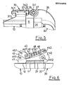
- FIG. 6 shows the design of a locking element as Over-dead center closure with claw 42.
- the base part 41 fastened to the last shot 12 of the container 10 extends beyond the flange ring 21, which projects outwards and is fastened to the web edge 22 of the closure cover 20.
- a handlebar is on the container side by means of a pivot bolt 41.1 43 attached, while the claw 42 is pivotally attached to the base part 41 on the container side with a second pivot pin 41.2.
- a push rod 47 which is fastened to the handlebar 43 by means of the pivot pin 44.1 and to the claw by means of the pivot pin 44.2, transmits the movement of the handlebar 43 to the claw 42.
- the lower edge of the handlebar 43 lies on one in the base part 41 provided adjustment screw 49, with which the position of the handlebar 43 can be adjusted so that the dead center is exceeded by a slight distance when closing.
- the eye 43.1 provided on the handlebar serves as a point of application for a power source, for example a hydraulic cylinder.
- the push rod 47 is screwed into the end pieces 45 and 46, which comprise forks, the links 43 and the claw 42, the threads having opposite slopes.
- the push rod 47 can be rotated and thus the distance between the axes of the eyebolts 44.1 and 44.2 can be adjusted such that tightness of the flanges 11 and 21 sealed with the round cord seal (not shown in more detail) is achieved.
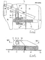
- FIGS. 7 and 8 show a bolt lock in which two jaws 52 are provided on the outside of the container-side flange ring 11 for each locking element, which are aligned essentially parallel to the axis and whose opening facing the lock bottom serves as an inlet opening for the lock bottom side lock receptacle 51 are still open.
- the closure base is closed, the bolt receptacle 51 lies between the two jaws 52 and the bolt 54 can be inserted into the opening 53 of the bolt receptacle.
- the side facing the closure base is supported against the end faces of the jaws 52. It goes without saying that this end face by gutting the jaws can be moved back, the side protrusions leading the latch.
- the opening 53 in the bolt receptacle 51 is provided on its side facing the container 10 with an inclined surface 51.1 corresponding to the bevel of the inclined surface 54.1 of the bolt, both inclined surfaces cooperating with one another in the manner of a wedge lock.
- An eye bolt 55 which cooperates with a lever 56, is screwed into the bolt 54, the lever as a two-armed lever being able to be pivoted about the pivot bolt 57 - as indicated in FIG. 7 by the dashed double arrow.
- the bolt 54 is taken over the eyebolt 55 and the eye 55.1 to which the lever 56 is attached, and swings out - as shown in FIG. 7 with the dashed double arrow.
- the free end of the lever 56 is provided with a coupling 58 which connects this lever to the other levers of the locking members.
- One of the levers 56 carries an extension 56.1 which is designed as a handle for manual operation or which is connected to any other power source and via which all bolts can be lifted or inserted at the same time.
- the eyebolt 55.1 is expediently designed as a fork which includes the lever 56.
- the adjustability of the eyebolt 55 is given by screwing it into the lever 54, the desired position being fixed by the lock nut 55.2. This fixation also keeps the levers 54 in the correct position for insertion.
Abstract
Description
Die Erfindung betrifft einen Behälter für Flüssigkeiten, Schlämme u. dgl., der stirnseitig mit einem klöpperbodenartig gewölbten Boden öffenbar verschlossen ist, wobei der Boden schwenkbar an die Behälterwand, an der über ihren Umfang verteilt mehrere mit dem Boden zusammenwirkende Verriegelungselemente vorgesehen sind, angelenkt ist, insbesondere für Entsorgungsfahrzeuge.The invention relates to a container for liquids, sludges and. Like., The front side is openably closed with a dished bottom curved bottom, wherein the bottom is pivotally articulated to the container wall, on which several locking elements cooperating with the bottom are provided distributed over its circumference, in particular for disposal vehicles.
Behälter zur Aufnahme von Flüssigkeiten, Schlämmen u. dgl. bedürfen der vollständigen Entleerung und sie müssen von Zeit zu Zeit gereinigt werden. Um dies zu erreichen, wird einer der den Behälter verschließenden Böden an den Behälter angelenkt, so daß der Behälter durch Aufschwenken des Bodens geöffnet werden kann. Der Schwachpunkt dieser Anordnung liegt in der Dichtung. Bei den bisherigen Anordnungen wird eine Stehkante auf eine in einer U-Nut befindlichen Dichteinlage gedrückt, wobei ein hinreichend großer Hub zum Erzielen einer vollständigen Abdichtung ringsum notwendig ist. Durch diesen großen Hub wird die Dichtung über Gebühr beansprucht, so daß die Dichtungsauswahl auf einige Materialien beschränkt ist. Da die vom Behälter aufzunehmenden Flüssigkeiten, Schlämme o. dgl., jedoch die unterschiedlichsten Anforderungen an die Dichtungsmaterialien stellen, schränkt die Beschränkung der verwendbaren Dichtungsmaterialien die Verwendbarkeit des Behälters ein. Darüber hinaus führt der große Hub dazu , daß die Verschlußkonstruktionen entsprechend aufwendig ausgeführt werden müssen und - eben wegen des großen Hubes - nicht einfach entriegelbar sind. Ein weiterer sicherheitstechnischer Aspekt ist dadurch gegeben, daß unter bestimmten Umständen Verpuffungen im Behälter zu einem schnellen Druckanstieg führen können. Sind - wie bei undefinierten Flüssigkeiten und Schlämmen im Bereich des Möglichen - die Sicherheitseinrichtungen verklebt, führt der Druckaufbau zum Aufreißen des Behälters, da für den zu einem Undichtwerden notwendigen Hub die Dehnungsgrenze der geschlossenen Verschlußglieder überschritten wird.Containers for holding liquids, sludges etc. The like. require complete emptying and they must be cleaned from time to time. To achieve this, one of the bottoms closing the container is hinged to the container so that the container can be opened by swinging the floor open. The weak point of this arrangement lies in the seal. In the previous arrangements, a standing edge is pressed onto a sealing insert located in a U-groove, a sufficiently large stroke being necessary to achieve a complete seal all around. This large stroke places excessive stress on the seal, so that the choice of seal is limited to some materials. However, since the liquids, sludges or the like to be taken up by the container place very different demands on the sealing materials, the limitation of the sealing materials which can be used limits the usability of the container. In addition, the large stroke leads to the fact that the closure structures have to be correspondingly complex and - precisely because of the large stroke - cannot be easily unlocked. Another safety aspect is that under certain circumstances, deflagrations in the container can lead to a rapid rise in pressure. If - as is possible with undefined liquids and sludges - the safety devices are glued, the pressure build-up leads to the tearing of the container, since the expansion limit of the closed closure members is exceeded for the stroke required for a leak.
Hier setzt die Erfindung ein, der die Aufgabe zugrunde liegt, einen Behälter vorzuschlagen, dessen Deckel mit geringem Hub dicht aufbringbar ist, bei dem die Dichtungen in einfacher Weise austauschbar sind und der sicher einsetzbar ist.This is where the invention comes in, which is based on the object of proposing a container whose cover can be tightly applied with a small stroke, in which the seals can be replaced in a simple manner and which can be used safely.
Diese Aufgabe wird nach der Erfindung dadurch gelöst, daß der Behälter und der Boden an den zueinander zugewandten Stirnflächen mit je einem Flanschring, dessen Breite mindestens der vierfachen Dicke der Behälterwand entspricht, versehen sind, deren einander zugewandte Kreisringflächen bei geschlossenem Behälter einander parallel gegenüberstehen, wobei eine der Kreisflächen mindestens eine umlaufende Nut aufweist, deren mittlere Weite etwa 1/3 der Breite der Kreisringfläche beträgt und wobei in die umlaufende Nut ein Dichtungsring, dessen Querabmessung der mittleren Weite der Nut entspricht, eingelegt ist. Damit wird ein Verschluß mit einem Dichtungsring mit gegenüber der Breite des Flansches kleiner Abmessung vorgeschlagen, wobei die Gegenfläche von der Planenoberfläche des Gegenflansches gebildet wird und bereits bei einem geringfügigen Hub die notwendige Abdichtung ringsum erreicht wird. Der in die Nut eingelegte Dichtring läßt sich in einfacher Weise austauschen, so daß beliebige für den Anwendungsfall jeweils geeignete Dichtungsmaterialien eingesetzt werden können. Sofern in besonderen Fällen die beständigen Materialien eine übergroße Härte aufweisen, können an sich bekannte Zweistoff-Dichtungen eingesetzt werden, bei denen ein aus den beständigen Material bestehender Überzug auf einen Kern aus einem Schaumstoffmaterial geeigneter Härte aufgebracht ist. Durch Einstellen der Dichtungshärte in den Bereich von 30 bis 70 Shore lassen sich die Dichtungskräfte auch bei Kesseldurchmessern bis etwa 3m sicher beherrschen. Da ein Anpressen im Bereich von 1/10 mm bereits die notwendige Dichtheit ringsum ergibt und da die Verschlußorgane eine Dehnung in dieser Größenordnung noch im elastischen Bereich überstehen, kann auch eine Verpuffung im Behälter allenfalls zu einem kurzzeitigen Undichtwerden führen, wenn der Druck nicht auf andere Weise abgeführt werden kann. Durch das kurzzeitige Undichtwerden wird der Überdruck im Bereich der Dichtung abgeblasen und eine Gefährdung der Umgebung durch einen aufreißenden Behälter ist ausgeschlossen. Sind in der mit Nuten versehenen Kreisringfläche des Kreisringes des einen Flansches zwei oder mehr Nuten vorgesehen, sind - entsprechend der Zahl der Nuten - mehrere Dichtungsringe eingesetzt, wobei mindestens der innerste, die für die vom Behälter aufzunehmende Flüssigkeit, Schlämme o.dgl. notwendige Beständigkeit aufweist. Der zwischen zwei Dichtringen vorhandene Ringraum kann bei einer derartigen Anordnung als Überwachungs- und Prüfeinrichtung benutzt werden. Hierzu wird der Ringraum unter einen vom Außendruck und vom Behälterinnendruck abweichenden Druck gesetzt, wobei es keine Rolle spielt ob dieser Druck ein Über- oder ein Unterdruck ist. Die Druckänderung oder aber der zum Halten des Druckes notwendige Gasstrom, der bei Überdruck zugeführt bzw. bei Unterdruck abgesaugt wird, gibt Aufschluß über die erreichte Dichtheit.This object is achieved according to the invention in that the container and the bottom of the mutually facing end faces are each provided with a flange ring, the width of which corresponds to at least four times the thickness of the container wall, the facing annular surfaces of which face each other in parallel when the container is closed, whereby one of the circular surfaces has at least one circumferential groove, the mean width of which is approximately 1/3 of the width of the circular ring surface, and being in the circumferential groove a sealing ring, the transverse dimension of which corresponds to the mean width of the groove, is inserted. A closure with a sealing ring with a dimension that is small compared to the width of the flange is thus proposed, the counter surface being formed by the tarpaulin surface of the counter flange and the necessary sealing all around being achieved even with a slight stroke. The sealing ring inserted into the groove can be replaced in a simple manner, so that any sealing materials suitable for the application can be used. If, in special cases, the resistant materials have an excessive hardness, known two-component seals can be used, in which a coating consisting of the resistant material is applied to a core made of a foam material of suitable hardness. By setting the seal hardness in the range from 30 to 70 Shore, the seal forces can be safely controlled even with boiler diameters up to about 3m. Since a pressure in the range of 1/10 mm already provides the necessary tightness all around and since the closure members can withstand an expansion of this magnitude in the elastic range, a deflagration in the container can also lead to a brief leak if the pressure is not on others Way can be dissipated. Due to the brief leak, the overpressure in the area of the seal is blown off and there is no danger to the environment from a tearing container. Are two or more grooves are provided in the grooved annular surface of the annular ring of the one flange, - depending on the number of grooves - several sealing rings are used, at least the innermost, or the like, for the liquid to be absorbed by the container. has the necessary stability. The annular space between two sealing rings can be used as a monitoring and testing device in such an arrangement. For this purpose, the annular space is placed under a pressure which differs from the external pressure and the internal pressure of the container, it being irrelevant whether this pressure is an overpressure or a vacuum. The pressure change or the gas flow necessary to maintain the pressure, which is fed in at overpressure or extracted at underpressure provides information about the tightness achieved.
Eine bevorzugte Ausführungsform ist dadurch gegeben, daß zur Anlenkung des Bodens an den Behälter ein ein- oder mehrfaches, vorzugsweise ein zweifaches Scharnier vorgesehen ist, das beidseits einen über HaltestUtzen an dem Mantel des Behälters befestigten Augbolzenhalter aufweist, in dem der Augbolzen geführt ist und das bodenseitig ein mit einem Auge versehener Ausleger am Bodenblech befestigt ist, wobei ein Verbindungsbolzen das Auge des Augbolzens und das Auge des Auslegers verbindet, und wobei der Aug- bolzen mit einem Gewinde versehen ist und mittels Mutter und Kontermutter am Augbolzenhalter einstellbar festlegbar ist. Durch diese Ausführungsform wird die für den geringen Hub notwendige Justierbarkeit des Verschlußbodens erreicht. Ebenso läßt sich - bei Mehrfach-Scharnieren - die zur Dichtheit notwendige Para11ilität`der bei geschlossenem Boden einander zugewandten Kreisringflächen der Flanschringe justieren. Dabei ist es selbstverständlich, daß die Justierschrauben ein hinreichend feines Gewinde aufweisen, und daß sie mittels Mutter und Kontermutter, ggf. unter Hinzufügung anderer Schraubensicherungen, festlegbar sind.A preferred embodiment is given in that a single or multiple, preferably a double hinge is provided for articulating the bottom of the container, which has on both sides an eyebolt holder fastened to the jacket of the container via holding supports, in which the eyebolt is guided and that the bottom side a provided with an eye bracket is secured to the base plate, wherein a connecting pin connects the eye of the eyebolt and the eye of the boom, and wherein the a bolt ug provided with a thread and is adjustable secured by means of nut and locknut at Augbolzenhalter. This embodiment achieves the adjustability of the closure base necessary for the small stroke. Likewise - in the case of multiple hinges - the parity required for tightness of the circular ring surfaces of the flange rings facing one another when the bottom is closed can be adjusted. It goes without saying that the adjusting screws have a sufficiently fine thread and that they can be fixed by means of a nut and lock nut, possibly with the addition of other screw locks.
Weiter wird vorgeschlagen, daß die Nut mindestens eine schwalbenschwanzartig hinterschnittene Seitenflanke aufweist. Darüber hinaus wird vorgeschlagen, daß die Nut in dem einen der Flanschringe eine Tiefe höchstens gleich dem Durchmesser des Dichtringes aufweist, wobei die Gegenfläche von der Kreisringfläche des anderen Flanschringes gebildet ist. Schließlich wird vorgeschlagen, daß auf der Kreisringfläche mit Nut des einen Flanschringes gegenüberliegenden Kreisringfläche des anderen Flanschringes mittig zur Nut ein erhabener, umlaufender, vorzugsweise im Querschnitt dreieckiger Vorsprung vorgesehen ist. Durch diese Ausbildung der Nut wird der Dichtring sicher gehalten. Darüber hinaus steht der Dichtring mit seiner Unterkante über die Ebene der mit der Nut zur Aufnahme des Dichtringes versehenen Kreisringfläche vor. Schließlich wird, dies ist besonders vorteilhaft bei harten Dichtungsmaterialien, die zur Abdichtung notwendige Kraft durch den vorzugsweise dreieckig geformten Vorsprung in der Gegenfläche verringert.It is further proposed that the groove has at least one side flank undercut in the manner of a dovetail. In addition, it is proposed that the groove in one of the flange rings have a depth at most equal to the diameter of the sealing ring, the counter surface being formed by the circular ring surface of the other flange ring. Finally, it is proposed that a raised, encircling projection, preferably triangular in cross section, is provided on the circular ring surface with the groove of the circular ring surface of the other flange ring opposite one flange ring in the center of the groove. The sealing ring is held securely by this design of the groove. In addition, the lower edge of the sealing ring projects beyond the plane of the circular ring surface provided with the groove for receiving the sealing ring. Eventually, this will is particularly advantageous for hard sealing materials, the force required for sealing is reduced by the preferably triangular-shaped projection in the counter surface.
Eine andere Ausführungsform ist dadurch gegeben, daß die Nut in dem einen der Flanschringe eine Tiefe mindestens gleich dem Durchmesser des Dichtringes aufweist, wobei die Gegenfläche von einem auf der Kreisringfläche des anderen Flanschringes vorgesehenen, erhabenen, umlaufenden, im Querschnitt rechteckigen Vorsprung gebildet ist, dessen Breite höchstens gleich der engsten Weite der Nut ist. Bei dieser Ausführungsform greift der Vorsprung der Gegenfläche in die Nut ein, und legt sich gegen den Dichtring, der geschützt im Inneren der Nut liegt. Es versteht sich von selbst, daß zur Verringerung der Kraft auch hier die mit dem Dichtring zusammenwirkende Vorderseite des Vorsprungs dreieckförmig ausgebildet sein kann. Durch den Vorsprung selbst wird dabei immer eine Zentrierung des Verschlußbodens erreicht. Der in die Nut/Nuten eingelegte Dichtring ist ein Endlos-Ring, der vorteilhafterweise als Rundschnurring ausgebildet ist. In einer anderen Ausbildungsform weist der Querschnitt des Dichtringes ein Dach-Profil auf. Bei beiden Formen ergeben sich Quasi-Linienanlagen, wodurch bei gegebener Kraft der die Dichtheit bestimmende Anlagedruck hinreichende Größe aufweist.Another embodiment is given in that the groove in one of the flange rings has a depth at least equal to the diameter of the sealing ring, the counter surface being formed by a raised, circumferential, cross-sectionally rectangular projection provided on the annular surface of the other flange ring Width is at most equal to the narrowest width of the groove. In this embodiment, the projection of the mating surface engages in the groove and lies against the sealing ring, which is protected inside the groove. It goes without saying that, in order to reduce the force, the front of the projection cooperating with the sealing ring can also be triangular in shape. A centering of the closure bottom is always achieved by the projection itself. The sealing ring inserted into the groove (s) is an endless ring, which is advantageously designed as a round cord ring. In another embodiment, the cross section of the sealing ring has a roof profile. Both forms result in quasi-linear systems, which means that the system pressure that determines the tightness is sufficiently large for a given force.
In einer Ausführungsform sind die mit dem Boden zusammenwirkenden Verriegelungselemente als Schraubverschlüsse ausgebildet. Dabei werden - in üblicher Weise - mit einem Schaftende an den Behälter bzw. an den Flanschring angelenkte Schraubbolzen in am Verschlußboden bzw. an dessen Flanschring befestigte gabelförmige Widerlager eingelegt und mittels Handräder angezogen. Diese Verschlußelemente sind über den Umfang des Behälters verteilt, wobei die Scharnierbefestigungen mit in die regelmäßige Verteilung einbezogen sind.In one embodiment, the locking elements interacting with the base are designed as screw closures. In this case - in the usual way - with a shaft end hinged to the container or to the flange ring, bolts are inserted into fork-shaped abutments fastened to the closure base or to its flange ring and tightened by means of handwheels. These closure elements are distributed over the circumference of the container, the hinge fastenings being included in the regular distribution.
Eine andere Befestigungsform des Bodens ist dadurch gegeben, daß die mit dem Boden zusammenwirkenden Verriegelungselemente als Riegelverschlüsse ausgebildet sind, wobei jeder der Riegelverschlüsse mit einem tangential zu den Flanschringen bewegbaren Riegel versehen ist, und jeder der eingesetzten Riegel mit einer Außenfläche gegen eine behälterfeste Gegenfläche abgestützt ist, während eine der Außenflächen gegenüber angeordnete Schrägfläche mit einer ihrer Schräge entsprechenden bodenfesten Gegenfläche an einer Riegelaufnahme im Sinne eines Keilverschlusses zusamlenwirkt. Weiter wird vorgeschlagen, daß die behälterfeste Gegenfläche von den Stirnseiten von auf dem behälterseitigen Flanschring vorgesehenen Backen gebildet ist, wobei die Backen axial ausgerichtet sind und zur Öffnungsseite des Behälters hin eine den Abstand zwischen ihnen vergrößernde Abknickung aufweisen und daß auf dem bodenseitigen Flanschring eine axial ausgerichtete, zwischen die Backen einführbare Riegelaufnahme vorgesehen ist, wobei die Riegelaufnahme eine Öffnung aufweist, deren Querschnitt dem Querschnitt des einzuführenden Riegels entspricht, wobei die den freien Ende der Rieqelaufnahme zugewandte Innenwand der Öffnung die mit der Schrägfläche des Riegels zusammenwirkende Schrägfläche bildet. Schließlich wird vorgeschlagen, daß jeder der Riegel an seinem Ende einen einstellbaren Augbolzen aufweist, dessen Auge mit dem einen Ende eines Hebels zusammenwirkt, daß jeder der Hebel um einen behälterfesten Bolzen drehbar ist und daß alle freien Enden der Hebel aller Riegelverschlüsse über eine den Behälter umfassende Koppel miteinander verbunden sind, wobei als Antrieb der Koppel einer der Hebel über das Auge eines der Riegel hinaus eine Verlängerung aufweist. Durch diese Ausbildung der Verschlußelemente wird eine mechanisch betätigbare Verriegelung vorgegeben, wobei die Riegel in Riegelaufnahmen einsetzbar sind, wobei die verschlußbodenfesten Riegelaufnahmen zwischen behälterfesten Backen einführbar sind und der Riegel sich sowohl gegen die Stirnflächen der Backen als auch gegen eine der Stirnfläche gegenüberliegende Innenwand einer Öffnung der Riegelaufnahme abstützt. Die Keilform des Riegels gestattet einmal ein leichtes Einführen, auch wenn der Verschlußboden noch nicht seine endgültige Position erreicht hat und erlaubt darüber hinaus die für die Abdichtung notwendigen Anpreßkräfe aufzubringen. Um besonders bei großen Durchmessern das Einführen der Riegelaufnahme zwischen die Backen zu erleichtern, erhalten die Backen eine den Abstand zwischen ihnen vergrößernde Abknickung. Durch eine Koppel lassen sich alle Riegel gemeinsam betätigen. Dabei ist die Koppel um den Behälter geführt und mit Hebeln versehen, die um einen behälterfesten Bolzen drehbar gelagert sind. Am freien Ende der Hebel befinden sich die in die Regelaufnahme einführbaren Riegel. Der Antrieb kann an der Koppel selbst angreifen; vorteilhaft ist es auch, einen der Hebel zu verlängern, wobei die Verlängerung die Funktion des Antriebshebels übernimmt. Der Antrieb selbst kann mit einer Kraftquelle, z.B. einem Hydraulikzylinder versehen sein, eine Handbetätigung über einen Handgriff an der Koppel oder einen Handgriff an der Hebelverlängerung ist ebenfalls möglich.Another form of attachment of the floor is given in that the locking elements interacting with the floor as a Rie gel closures are formed, each of the bolt closures being provided with a bolt which can be moved tangentially to the flange rings, and each of the bolts used is supported with an outer surface against a container-fixed mating surface, while one of the outer surfaces arranged opposite one another with a bevel-fixed mating surface corresponding to its slope bolt receptacle together enwirkt l in terms of a wedge lock. It is further proposed that the counter surface fixed to the container is formed by the end faces of jaws provided on the flange ring on the container side, the jaws being axially aligned and having a kink increasing the distance between them towards the opening side of the container and that an axially aligned flange ring on the bottom side , between the jaws insertable bolt receptacle is provided, the bolt receptacle having an opening whose cross-section corresponds to the cross section of the bolt to be inserted, the inner wall of the opening facing the free end of the bolt receptacle forming the inclined surface cooperating with the oblique surface of the bolt. Finally, it is proposed that each of the bolts has an adjustable eyebolt at its end, the eye of which cooperates with the one end of a lever, that each of the levers can be rotated about a bolt that is fixed to the container, and that all free ends of the levers of all bolt locks are encompassed by a container Couplings are connected to one another, with the coupling of one of the levers extending beyond the eye of one of the bolts as the drive for the coupling. This design of the closure elements provides a mechanically actuable locking device, the bolts being usable in bolt receptacles, the bolt-bottom fixed bolt receptacles being insertable between container-fixed jaws, and the bolt being pressed against both the end faces of the jaws and against an inner wall of an opening opposite the end face Bolt holder supports. The wedge shape of the bolt allows easy insertion even if the bottom of the fastener has not yet reached its final position and also allows the necessary contact pressure to be applied. In order to make it easier to insert the bolt holder between the jaws, especially with large diameters, the jaws are given a kink that increases the distance between them. Leave through a paddock all bars operate together. The coupling is guided around the container and provided with levers which are rotatably mounted about a bolt that is fixed to the container. At the free end of the levers are the latches that can be inserted into the standard holder. The drive can attack the coupling itself; It is also advantageous to extend one of the levers, the extension taking over the function of the drive lever. The drive itself can be provided with a power source, for example a hydraulic cylinder, manual operation via a handle on the coupling or a handle on the lever extension is also possible.
In einer dritten Ausführungsform schließlich sind die mit dem Boden zusammenwirkende Verriegelungselemente als Über-Todpunkt-Verschlüsse ausgebildet, wobei jedes der Verriegelungselemente mit einer Kralle hinter eine Pratze am Behälterdeckel greift und jede der Kralle über eine Schubstange und einen Lenker mit einem behälterfesten Basisteil verbunden sind. Weiter wird vorgeschlagen, daß der Lenker bei geschlossenem Verriegelungselement auf einem im Basisteil vorgesehenen, verstellbaren Justierbolzen aufliegt. Durch diese Ausbildung wird es möglich axial wirkende Verriegelungselemente zu schaffen, die besonders auch mit Kraftquellen, z.B. mit Hydraulikzylindern antreibbar sind. Die Auflage auf einen verstellbaren Justierbolzen wirkt auf die Über-Todpunkt-Lage bei geschlossenem Verschluß. Dieser Justierbolzen verhindert ein übergroßes Überschreiten der Todpunkt-Lage, wodurch ein unerwünschtes Entspannen, was im Hinblick auf den geringen Hub möglicherweise zu Undichtheiten führen könnte, vermieden wird.In a third embodiment, finally, the locking elements interacting with the bottom are designed as over-dead-point locks, each of the locking elements engaging behind a claw on the container lid with a claw and each of the claws being connected to a base part fixed to the container via a push rod and a handlebar. It is further proposed that the handlebar rests on an adjustable adjusting bolt provided in the base part when the locking element is closed. This design makes it possible to create axially acting locking elements that are also particularly suitable with power sources, e.g. can be driven with hydraulic cylinders. The support on an adjustable adjustment bolt acts on the over-dead center position when the lock is closed. This adjusting bolt prevents the dead center position from being exceeded excessively, thereby preventing undesired relaxation, which could possibly lead to leaks in view of the short stroke.
Eine Weiterbildung ist dadurch gegeben, daß der Flanschring am Behälterdeckel nach außen überstehend angeordnet ist und die Pratze für den Angriff der Kralle des Verriegelungselements bildet. Weiter wird vorgeschlagen, daß die Schubstange zwischen Lenker und Kralle mindestens in ihren Endbereichen mit die Justierung der Lage der Kralle ermöglichenden Gewinden versehen ist. Schließlich wird vorgeschlagen, daß die in den beiden Endbereichen der Schubstange vorgesehenen Gewinde gegenläufige Gewinde sind, wobei das lenkerseitige Aufnahmestück und das krallenseitige Aufnahmestück für die Schubstange dazu korrespondierend ebenfalls gegenläufige Gewinde aufweisen. Schließlich wird vorgeschlagen, daß die Schubstange etwa in ihrer Mitte ein vorzugsweise als Sechskant ausgebildetes Paßstück aufweist. Durch die Anordnung des Flanschrings am Behälterdeckel werden eigene Pratzen überflüssig. Es ist dabei unerheblich, ob der behälterseitige Flanschring nach außen übersteht, da der klöpperbodenartig gewölbte Verschlußboden nicht notwendigerweise mit der Behälterwand fluchten muß, sondern im Flanschinneren angesetzt sein kann. Im Hinblick auf die Reinigungsmöglichkeit des Behälters empfiehlt es sich jedoch auch den behälterseitigen Flanschring nach außen überstehend anzuordnen. Die Justierbarkeit der Schubstange wirkt bei behälterseitig festem Anlenkpunkt auf die Lage der Kralle bei geschlossenem Verriegelungselement. Dies ist im Hinblick auf den geringen Hub besonders dann von Vorteil, wenn beispielsweise der Behälterflansch oder der Deckelflansch verzogen sind. Durch gegenläufige Gewinde in beiden Endbereichen der Schubstange wird ein justieren in einfacher Weise möglich, da beim Drehen der Schubstange auf beiden Seiten gegenläufige Bewegungen erfolgen. In einfacher Weise kann die Schubstange gedreht werden, wenn etwa in ihrer Mitte ein mit einem Gabelschlüssel faßbares Paßstück angeordnet ist.A further development is given in that the flange ring on the container lid is arranged to protrude outwards and forms the claw for the attack of the claw of the locking element. It is further proposed that the push rod between the handlebar and the claw is provided with threads enabling the position of the claw to be adjusted at least in its end regions. Finally, it is proposed that in the two end regions of the push rod provided threads are counter-rotating threads, the handlebar receiving piece and the claw-side receiving piece for the push rod correspondingly also having opposite threads. Finally, it is proposed that the push rod has an adapter, preferably in the form of a hexagon, approximately in its center. The arrangement of the flange ring on the container lid means that there is no need for your own claws. It is irrelevant whether the flange ring on the container side protrudes outwards, since the closure base, which is curved in the manner of a clapper bottom, does not necessarily have to be flush with the container wall, but rather can be attached inside the flange. With regard to the possibility of cleaning the container, however, it is also advisable to arrange the flange ring on the container side projecting outwards. The adjustability of the push rod affects the position of the claw with the locking element closed when the articulation point is fixed on the container side. In view of the short stroke, this is particularly advantageous if, for example, the container flange or the cover flange are distorted. By means of counter-rotating threads in both end areas of the push rod, an adjustment is possible in a simple manner, since counter-rotating movements occur on both sides when the push rod is turned. The push rod can be rotated in a simple manner if a fitting piece which can be gripped with an open-ended wrench is arranged approximately in the middle.
Die Anordnung eines Lenkers, der mit einem Loch versehen ist, ermöglicht den Anschluß eines Hydraulikzylinders zur Betätigung des Verriegelungselements. Darüber hinaus gelingt es, den Behälter auch dann zu öffnen, wenn etwa die Hydraulik ausgefallen ist. Die nur geringfügig über den Todpunkt hinausgehende Endlage gestattet es nämlich, daß ohne wesentlichen Kraftaufwand am Loch des Lenkers angreifend, das Verriegelungselement gelöst wird.The arrangement of a handlebar, which is provided with a hole, enables the connection of a hydraulic cylinder for actuating the locking element. In addition, it is possible to open the container even if the hydraulic system has failed. The end position, which extends only slightly beyond the point of death, allows the locking element to be released when the handlebar hole is engaged without any significant effort.
Das Wesen der Erfindung wird anhand der Figuren 1 bis 8 näher erläutert, dabei zeigen
- Figur 1 das hintere Ende eines öffenbaren Behälters mit Verschlußboden in Seitansicht
- Figur 2 das hintere Ende eines öffenbaren Behälters mit Verschlußboden in rückwärtiger Ansicht
- Figur 3 Flanschdichtung, Querschnitt
- Figur 4 Flanschdichtung, Querschnitt
- Figur 5 Scharnieranlenkung des Verschlußbodens an den Behälter
- Figur 6 geschlossener Krallenverschluß mit - teilgeschnittenen - Flanschringen
- Figur 7 Riegelverschluß-Aufsicht, teilgeschnitten, gemäß VII-VII (Figur 8)
- Figur 8 Riegelverschluß ohne Riegel, Aufsicht, teilgeschnitten
- Figure 1 shows the rear end of an openable container with a closure bottom in a side view
- Figure 2 shows the rear end of an openable container with a closure bottom in a rear view
- Figure 3 flange seal, cross section
- Figure 4 flange seal, cross section
- Figure 5 hinge linkage of the closure bottom to the container
- Figure 6 closed claw lock with - partially cut - flange rings
- FIG. 7 top view of the bolt closure, partially cut, in accordance with VII-VII (FIG. 8)
- Figure 8 bolt lock without bolt, supervision, partially cut
Die Figuren 1 und 2 zeigen - schematisch - das öffenbare Ende eines Behälters 10, das mit einem klöpperbodenartig gewölbten Deckel 20 verschlossen ist. Der Verschlußdeckel 20 ist mittels eines Scharniers 30 am Behälter 10 befestigt. Dieses Scharnier kann im Scheitelbereich des Behälters 10 - Figur 1 - vorgesehen sein; es kann sich auch - Figur 2 - seitlich am Behälter befinden. Während im ersten Fall der Verschlußboden 20 nach oben aufgeschwenkt wird und sich um eine im wesentlichen horizontale Schwenkachse dreht, wird im zweiten Fall der Verschlußboden 20 um eine vertikale Drehachse (die strichpunktiert in Figur 2 angedeutet ist) zur Seite geschwenkt. Die Scharnieranordnung im Scheitelbereich des Behälters 10 bietet sich dann an, wenn - etwa zur Reinigung - der Behälter 10 mit seinem vorderen - in Figur 1 nicht näher dargestellten - Teil angehoben wird um Schlamm u.dgl. die Möglichkeit zum Abfliessen zu geben. Die über den Umfang verteilten Verriegelungsorgane 40 sind in Figur 1 als hydraulische Zylinder dargestellt, die am Behälter 10 befestigt mit einer an dem Schubstangenende befestigten Kralle mit dem Verschlußdeckel 20 zusammenwirken. Dabei werden die am Ende des Behälters 10 und der dem Behälter zugewandten Seite des Verschlußbodens 20 vorgesehenen Flanschen 11 und 21 gegeneinander gedrückt.Figures 1 and 2 show - schematically - the openable end of a
Die Figuren 3 und 4 zeigen Einzelheiten der Flanschen 11 und 21 im geschlossenen Zustand. Der am letzten Schuß 12 des Behälters 10 vorgesehene behälterseitige Flansch 11 ist mit einer Nut 13 versehen, in der eine Runddichtung 14 eingelegt ist. Der am Verschlußbodenrand 22 befestigte Flansch 21 wirkt mit seiner stirnseitigen Gegenfläche mit der Rundschnurdichtung zusammen und stellt bei entsprechendem Anpreßdruck die Dichtheit zwischen beiden Flanschen her. Die Ausführungsform nach Figur 4 enthält eine gegenüber dem Durchmesser der Rundschnurdichtung 14 vertiefte Nut 13, in die ein auf der gegenüberliegenden kreisringförmigen Stirnseite des behälterseitigen Flansches 21 angeordneter Vorsprung 23 eingreift. Dieser Vorsprung, der mit guter Passung hergestellt sein kann, wirkt mit dem Dichtring zusammen und sorgt für eine Zentrierung des Verschlußdeckels. Darüber hinaus besteht eine labyrinthdichtungsähnliche Wirkung.Figures 3 and 4 show details of the
Die Figur 5 zeigt die Ausbildung des Scharniers 30, das mit Halterstützen 31.1 am letzten Schuß 12 des Behälters 10 befestigt ist. Die Halterstützen 31.1 tragen Bolzenhalter 31. In jedem der Bolzenhalter 31 ist ein Augbolzen 32 eingeführt, dessen Bolzenschaft mit einem Gewinde versehen ist. Feststell- Kontermuttern 34.1 und 34.2 gestatten es, die Lage des Bolzens in dem Augbolzenhalter justierbar zu verändern. Das andere Ende des Augbolzens 32 ist mit einem Auge 33 versehen, das mit dem am klöpperbodenartig gewölbten Deckel 22 befestigten Ausleger 26, der mit einem Lenkerauge 27 versehen ist, zusammenwirkt. Das Auge des Augbolzens 33 und das Auge des Lenkers 27 werden dabei durch den Augbolzen 33.1 schwenkbar zusammengehalten. Durch diese Konstruktion des Lagers ist die Einstellungsmöglichkeit gegeben, die die Ringsum-Dichtheit auch bei verzogenem Flansch herzustellen gestattet.FIG. 5 shows the design of the
Die Figur 6 zeigt die Ausbildung eines Verriegelungselements als Über-Todpunkt-Verschluß mit Kralle 42. Das am letzten Schuß 12 des Behälters 10 befestigte Basisteil 41 reicht bis über den an der Stegkante 22 des Verschlußdeckels 20 befestigten, nach außen überstehenden verschlußdeckelseitigen Flanschringes 21. Auf der Behälterseite ist mittels eines Drehbolzens 41.1 ein Lenker 43 befestigt, während behälterseitig mit einem zweiten Drehbolzen 41.2 die Kralle 42 am Basisteil 41 schwenkbar befestigt ist. Eine Schubstange 47, die mittels des Drehbolzens 44.1 am Lenker 43 und mittels des Drehbolzens 44.2 an der Kralle befestigt ist, überträgt die Bewegung des Lenkers 43 auf die Kralle 42. In geschlossener Stellung liegt der Lenker 43 mit seiner unteren Kante auf einer im Basisteil 41 vorgesehenen Justierschraube 49 auf, mit der die Lage des Lenkers 43 gerade so eingestellt werden kann, daß beim Schließen der Todpunkt um eine geringfügige Wegstrecke überschritten wird. Das am Lenker vorgesehene Auge 43.1 dient als Angriffspunkt für eine Kraftquelle, beispielsweise einen Hydraulikzylinder. Die Schubstange 47 ist in den mit Gabeln,den Lenkern 43 bzw. die Kralle 42 umfassenden Endstücken 45 und 46 eingeschraubt, wobei die Gewinde gegenläufige Steigung aufweisen. Mittels des als Sechskant ausgebildeten Paßstückes 48 kann die Schubstange 47 verdreht und somit die Entfernung der Achsen der Augbolzen 44.1 und 44.2 voneinander so justiert werden, daß Dichtheit der mit der (nicht näher dargestellten) Rundschnurdichtung gedichteten Flansche 11 und 21 erreicht wird.FIG. 6 shows the design of a locking element as Over-dead center closure with claw 42. The
Die Figuren 7 und 8 schließlich zeigen einen Riegelverschluß, bei dem auf der Außenseite des behälterseitigen Flanschringes 11 für jedes Verriegelungselement zwei Backen 52 vorgesehen sind, die im wesentlichen parallel zur Achse ausgerichtet sind und deren zum Verschlußboden zugewandten Öffnung als Einlauf-Öffnung für die verschlußbodenseitige Riegelaufnahme 51 weiter geöffnet sind. Bei geschlossenem Verschlußboden liegt die Riegelaufnahme 51 zwischen den beiden Backen 52 und es kann der Riegel 54 in die Öffnung 53 der Riegelaufnahme eingeführt werden. Die dem Verschlußboden zugewandte Seite stützt sich dabei gegen die Stirnflächen der Backen 52 ab. Es versteht sich von selbst, daß diese Stirnfläche durch Ausnehmen der Backen zurückverlegt sein kann, wobei die seitlichen Überstände den Riegel führen. Die Öffnung 53 in der Riegelaufnahme 51 ist auf ihrer dem Behälter 10 zugewandten Seite mit einer der Schräge der Schrägfläche 54.1 des Riegels entsprechenden Schrägfläche 51.1 versehen, wobei beide Schrägflächen im Sinne eines Keilverschlußes miteinander zusammenwirken. In den Riegel 54 ist ein Augbolzen 55 eingeschraubt, der mit einem Hebel 56 zusammenwirkt, wobei der Hebel als zweiarmiger Hebel drehbar um den Drehbolzen 57 - wie in Figur 7 durch den gestrichelten Doppelpfeil angedeutet - geschwenkt werden kann. Dabei wird der Riegel 54 über den Augbolzen 55 und das Auge 55.1 an dem der Hebel 56 befestigt ist, mitgenommen und schwenkt - wie in Figur 7 mit dem gestrichelten Doppelpfeil dargestellt - aus. Das freie Ende des Hebels 56 ist mit einer Koppel 58 versehen, die diesen Hebel mit den anderen Hebeln der Verriegelungsorgane verbindet. Einer der Hebel 56 trägt eine Verlängerung 56.1, die als Handgriff ausgebildet zur Handbetätigung dient oder die mit einer anderen beliebigen Kraftquelle verbunden ist und über die alle Riegel gleichzeitig ausgehoben oder eingesetzt werden können. Zweckmäßigerweise ist der Augbolzen 55.1 als Gabel ausgebildet, die den Hebel 56 umfaßt. Die Einstellbarkeit des Augbolzens 55 ist durch das Einschrauben in den Hebel 54 gegeben, wobei die gewünschte Stellung durch die Kontermutter 55.2 fixiert wird. Durch diese Fixierung werden die Hebel 54 auch in der für ein Einführen richtigen Stellung gehalten.Finally, FIGS. 7 and 8 show a bolt lock in which two
Claims (19)
Priority Applications (1)
| Application Number | Priority Date | Filing Date | Title |
|---|---|---|---|
| AT86111205T ATE73728T1 (en) | 1985-08-14 | 1986-08-13 | LOCKABLE CONTAINER FOR LIQUIDS, SLUDGES OR THE LIKE. |
Applications Claiming Priority (2)
| Application Number | Priority Date | Filing Date | Title |
|---|---|---|---|
| DE3529081 | 1985-08-14 | ||
| DE19853529081 DE3529081A1 (en) | 1985-08-14 | 1985-08-14 | DISCLOSABLE CONTAINER FOR LIQUIDS, SLUDGE OR THE LIKE |
Publications (3)
| Publication Number | Publication Date |
|---|---|
| EP0214493A2 true EP0214493A2 (en) | 1987-03-18 |
| EP0214493A3 EP0214493A3 (en) | 1988-05-04 |
| EP0214493B1 EP0214493B1 (en) | 1992-03-18 |
Family
ID=6278449
Family Applications (1)
| Application Number | Title | Priority Date | Filing Date |
|---|---|---|---|
| EP86111205A Expired - Lifetime EP0214493B1 (en) | 1985-08-14 | 1986-08-13 | Lockable drum for liquids, sludges or the like |
Country Status (3)
| Country | Link |
|---|---|
| EP (1) | EP0214493B1 (en) |
| AT (1) | ATE73728T1 (en) |
| DE (2) | DE3529081A1 (en) |
Cited By (1)
| Publication number | Priority date | Publication date | Assignee | Title |
|---|---|---|---|---|
| EP0291831A2 (en) * | 1987-05-17 | 1988-11-23 | UTEF - MABO, UTEF Umwelt-Technik Entsorgungs-Fahrzeuge Ges. für Entw. Konstruktionen und Patentverwertung mbH & Co, MABO KG | Blocking device for key bolts |
Citations (7)
| Publication number | Priority date | Publication date | Assignee | Title |
|---|---|---|---|---|
| GB557372A (en) * | 1942-05-15 | 1943-11-17 | Brookhirst Switchgear Ltd | Improvements in or relating to hinges |
| US2700790A (en) * | 1952-02-15 | 1955-02-01 | Paul J Johnson | Combined hinge and head bolt for compression tanks |
| CH372781A (en) * | 1959-03-14 | 1963-10-31 | Ygnis Ag | Doors for boilers that work especially under overpressure |
| US3924780A (en) * | 1973-11-28 | 1975-12-09 | Gen Electric | Pressure hopper |
| CH575873A5 (en) * | 1974-02-28 | 1976-05-31 | Spitzer Silo Fahrzeugwerk Kg | |
| DE2543731A1 (en) * | 1975-10-01 | 1977-04-14 | Ernst Huebers | Rapid action clamp for pressure vessel end covers - has clamping load exerted by number of hydraulic cylinders operating on peripheral flange |
| US4466551A (en) * | 1983-02-28 | 1984-08-21 | Leung Kam F | Closure device |
Family Cites Families (8)
| Publication number | Priority date | Publication date | Assignee | Title |
|---|---|---|---|---|
| DE7829365U1 (en) * | 1979-01-11 | Gabler Gmbh & Co Kg, 4230 Wesel | Connection between the hinged lid and the pressure vessel | |
| FR330572A (en) * | 1903-03-25 | 1903-08-21 | Fulbert Calmant | Quick eccentric and ratchet clamp |
| CH114546A (en) * | 1925-05-29 | 1926-06-16 | Bucher Guyer Ag Masch | Device for connecting a hose line to a liquid manure line with a rotatable closing slide. |
| DE1866181U (en) * | 1962-08-27 | 1963-01-24 | Josef Kaiser | LIQUID TRANSPORT VEHICLE. |
| DE6607123U (en) * | 1968-07-16 | 1971-01-14 | Fritz Georg | LIQUID RESERVOIR, IN PARTICULAR HEATING OIL TANK |
| DE1793182A1 (en) * | 1968-08-13 | 1971-07-01 | Bayer Ag | Process for the preparation of 2-methylalkanols |
| DE1909857A1 (en) * | 1969-02-27 | 1970-09-10 | Konrad Ziesling | Electric cooking process |
| DE3131517A1 (en) * | 1981-08-08 | 1983-02-17 | Karl 8901 Welden Wiedemann | Container for aggressive liquids |
-
1985
- 1985-08-14 DE DE19853529081 patent/DE3529081A1/en not_active Withdrawn
-
1986
- 1986-08-13 AT AT86111205T patent/ATE73728T1/en not_active IP Right Cessation
- 1986-08-13 EP EP86111205A patent/EP0214493B1/en not_active Expired - Lifetime
- 1986-08-13 DE DE8686111205T patent/DE3684390D1/en not_active Expired - Fee Related
Patent Citations (7)
| Publication number | Priority date | Publication date | Assignee | Title |
|---|---|---|---|---|
| GB557372A (en) * | 1942-05-15 | 1943-11-17 | Brookhirst Switchgear Ltd | Improvements in or relating to hinges |
| US2700790A (en) * | 1952-02-15 | 1955-02-01 | Paul J Johnson | Combined hinge and head bolt for compression tanks |
| CH372781A (en) * | 1959-03-14 | 1963-10-31 | Ygnis Ag | Doors for boilers that work especially under overpressure |
| US3924780A (en) * | 1973-11-28 | 1975-12-09 | Gen Electric | Pressure hopper |
| CH575873A5 (en) * | 1974-02-28 | 1976-05-31 | Spitzer Silo Fahrzeugwerk Kg | |
| DE2543731A1 (en) * | 1975-10-01 | 1977-04-14 | Ernst Huebers | Rapid action clamp for pressure vessel end covers - has clamping load exerted by number of hydraulic cylinders operating on peripheral flange |
| US4466551A (en) * | 1983-02-28 | 1984-08-21 | Leung Kam F | Closure device |
Cited By (2)
| Publication number | Priority date | Publication date | Assignee | Title |
|---|---|---|---|---|
| EP0291831A2 (en) * | 1987-05-17 | 1988-11-23 | UTEF - MABO, UTEF Umwelt-Technik Entsorgungs-Fahrzeuge Ges. für Entw. Konstruktionen und Patentverwertung mbH & Co, MABO KG | Blocking device for key bolts |
| EP0291831A3 (en) * | 1987-05-17 | 1989-02-22 | Utef - Mabo Utef Umwelt-Technik Entsorgungs-Fahrzeuge Gesellschaft Fur Entwicklung, Konstruktionen Und Patentverwertung Mbh & | Blocking device for key bolts |
Also Published As
| Publication number | Publication date |
|---|---|
| DE3529081A1 (en) | 1987-02-26 |
| ATE73728T1 (en) | 1992-04-15 |
| EP0214493A3 (en) | 1988-05-04 |
| DE3684390D1 (en) | 1992-04-23 |
| EP0214493B1 (en) | 1992-03-18 |
Similar Documents
| Publication | Publication Date | Title |
|---|---|---|
| DE3040786C2 (en) | ||
| DE3422546C2 (en) | Container cap | |
| DE60305755T2 (en) | Locking system for mounting between two elements | |
| DE3403824A1 (en) | COLLECTIBLE FOR REUSABLE COLLECTIBLES | |
| DE3640440A1 (en) | FOLDING LOCK FOR A LID | |
| EP0214493A2 (en) | Lockable drum for liquids, sludges or the like | |
| DE8523340U1 (en) | Openable container for liquids, sludge or the like. | |
| EP0216268A2 (en) | Plastic container with closure | |
| DE19548118C2 (en) | Double-lid lock for closing two openings that can be connected to each other | |
| DE4334486A1 (en) | Plastic container with engageable lid | |
| EP0092639B1 (en) | Large capacity stackable containers, in particular silos | |
| DE3819247A1 (en) | Double cover system for lock vessels | |
| DE1932956A1 (en) | Gas-tight closure for two corresponding openings in two containers, especially those for holding radioactive substances | |
| DE3626746C2 (en) | ||
| DE19609602A1 (en) | Water transfer shaft of lid and base segments | |
| DE2342591C3 (en) | Lockable plastic cover for side openings in hollow masts with round cross-section and the like. | |
| DE4033601A1 (en) | Watertight shaft closure for underground storage tanks - has three wing screws connecting inner lid to main lid | |
| DE1509762C3 (en) | Lid lock | |
| DE2048688C3 (en) | ||
| DE2806759C3 (en) | Bunghole closure for a pressure vessel | |
| DE2154449A1 (en) | Device for securing a manhole closure | |
| DE2127099C (en) | Closure device on a pressure vessel | |
| DE3031945A1 (en) | Liq. container closure system - has metal sleeve coaxial with threaded socket carrying two eyes for claw mechanism | |
| DE1525978C3 (en) | Removable hinged locking flap | |
| EP0593973A1 (en) | Odourless container for biowaste |
Legal Events
| Date | Code | Title | Description |
|---|---|---|---|
| PUAI | Public reference made under article 153(3) epc to a published international application that has entered the european phase |
Free format text: ORIGINAL CODE: 0009012 |
|
| AK | Designated contracting states |
Kind code of ref document: A2 Designated state(s): AT BE CH DE FR GB IT LI NL |
|
| PUAL | Search report despatched |
Free format text: ORIGINAL CODE: 0009013 |
|
| AK | Designated contracting states |
Kind code of ref document: A3 Designated state(s): AT BE CH DE FR GB IT LI NL |
|
| 17P | Request for examination filed |
Effective date: 19881029 |
|
| 17Q | First examination report despatched |
Effective date: 19900322 |
|
| GRAA | (expected) grant |
Free format text: ORIGINAL CODE: 0009210 |
|
| AK | Designated contracting states |
Kind code of ref document: B1 Designated state(s): AT BE CH DE FR GB IT LI NL |
|
| REF | Corresponds to: |
Ref document number: 73728 Country of ref document: AT Date of ref document: 19920415 Kind code of ref document: T |
|
| REF | Corresponds to: |
Ref document number: 3684390 Country of ref document: DE Date of ref document: 19920423 |
|
| ITF | It: translation for a ep patent filed |
Owner name: STUDIO JAUMANN |
|
| ET | Fr: translation filed | ||
| GBT | Gb: translation of ep patent filed (gb section 77(6)(a)/1977) | ||
| PLBE | No opposition filed within time limit |
Free format text: ORIGINAL CODE: 0009261 |
|
| STAA | Information on the status of an ep patent application or granted ep patent |
Free format text: STATUS: NO OPPOSITION FILED WITHIN TIME LIMIT |
|
| 26N | No opposition filed | ||
| PGFP | Annual fee paid to national office [announced via postgrant information from national office to epo] |
Ref country code: GB Payment date: 19940815 Year of fee payment: 9 |
|
| PGFP | Annual fee paid to national office [announced via postgrant information from national office to epo] |
Ref country code: DE Payment date: 19940818 Year of fee payment: 9 |
|
| PGFP | Annual fee paid to national office [announced via postgrant information from national office to epo] |
Ref country code: FR Payment date: 19940825 Year of fee payment: 9 Ref country code: AT Payment date: 19940825 Year of fee payment: 9 |
|
| PGFP | Annual fee paid to national office [announced via postgrant information from national office to epo] |
Ref country code: CH Payment date: 19940829 Year of fee payment: 9 Ref country code: BE Payment date: 19940829 Year of fee payment: 9 |
|
| PGFP | Annual fee paid to national office [announced via postgrant information from national office to epo] |
Ref country code: NL Payment date: 19940831 Year of fee payment: 9 |
|
| PG25 | Lapsed in a contracting state [announced via postgrant information from national office to epo] |
Ref country code: GB Effective date: 19950813 Ref country code: AT Effective date: 19950813 |
|
| PG25 | Lapsed in a contracting state [announced via postgrant information from national office to epo] |
Ref country code: LI Effective date: 19950831 Ref country code: CH Effective date: 19950831 Ref country code: BE Effective date: 19950831 |
|
| BERE | Be: lapsed |
Owner name: MABO ENTSORGUNGS-SYSTEME FAHRZEUG-MASCHINEN-APPAR Effective date: 19950831 |
|
| PG25 | Lapsed in a contracting state [announced via postgrant information from national office to epo] |
Ref country code: NL Effective date: 19960301 |
|
| GBPC | Gb: european patent ceased through non-payment of renewal fee |
Effective date: 19950813 |
|
| REG | Reference to a national code |
Ref country code: CH Ref legal event code: PL |
|
| PG25 | Lapsed in a contracting state [announced via postgrant information from national office to epo] |
Ref country code: FR Effective date: 19960430 |
|
| NLV4 | Nl: lapsed or anulled due to non-payment of the annual fee |
Effective date: 19960301 |
|
| PG25 | Lapsed in a contracting state [announced via postgrant information from national office to epo] |
Ref country code: DE Effective date: 19960501 |
|
| REG | Reference to a national code |
Ref country code: FR Ref legal event code: ST |
|
| PG25 | Lapsed in a contracting state [announced via postgrant information from national office to epo] |
Ref country code: IT Free format text: LAPSE BECAUSE OF NON-PAYMENT OF DUE FEES Effective date: 20050813 |