EP0214266B1 - Electronic spatial logical toy containing movable and/or rotatable elements - Google Patents
Electronic spatial logical toy containing movable and/or rotatable elements Download PDFInfo
- Publication number
- EP0214266B1 EP0214266B1 EP86901982A EP86901982A EP0214266B1 EP 0214266 B1 EP0214266 B1 EP 0214266B1 EP 86901982 A EP86901982 A EP 86901982A EP 86901982 A EP86901982 A EP 86901982A EP 0214266 B1 EP0214266 B1 EP 0214266B1
- Authority
- EP
- European Patent Office
- Prior art keywords
- elements
- sensors
- toy
- logical
- centre
- Prior art date
- Legal status (The legal status is an assumption and is not a legal conclusion. Google has not performed a legal analysis and makes no representation as to the accuracy of the status listed.)
- Expired
Links
Images

Classifications
-
- A—HUMAN NECESSITIES
- A63—SPORTS; GAMES; AMUSEMENTS
- A63F—CARD, BOARD, OR ROULETTE GAMES; INDOOR GAMES USING SMALL MOVING PLAYING BODIES; VIDEO GAMES; GAMES NOT OTHERWISE PROVIDED FOR
- A63F9/00—Games not otherwise provided for
- A63F9/06—Patience; Other games for self-amusement
- A63F9/0612—Electronic puzzles
-
- A—HUMAN NECESSITIES
- A63—SPORTS; GAMES; AMUSEMENTS
- A63F—CARD, BOARD, OR ROULETTE GAMES; INDOOR GAMES USING SMALL MOVING PLAYING BODIES; VIDEO GAMES; GAMES NOT OTHERWISE PROVIDED FOR
- A63F9/00—Games not otherwise provided for
- A63F9/06—Patience; Other games for self-amusement
- A63F9/08—Puzzles provided with elements movable in relation, i.e. movably connected, to each other
- A63F9/0826—Three-dimensional puzzles with slidable or rotatable elements or groups of elements, the main configuration remaining unchanged, e.g. Rubik's cube
-
- A—HUMAN NECESSITIES
- A63—SPORTS; GAMES; AMUSEMENTS
- A63F—CARD, BOARD, OR ROULETTE GAMES; INDOOR GAMES USING SMALL MOVING PLAYING BODIES; VIDEO GAMES; GAMES NOT OTHERWISE PROVIDED FOR
- A63F9/00—Games not otherwise provided for
- A63F9/24—Games using electronic circuits not otherwise provided for
- A63F2009/2401—Detail of input, input devices
- A63F2009/2436—Characteristics of the input
- A63F2009/2442—Sensors or detectors
-
- A—HUMAN NECESSITIES
- A63—SPORTS; GAMES; AMUSEMENTS
- A63F—CARD, BOARD, OR ROULETTE GAMES; INDOOR GAMES USING SMALL MOVING PLAYING BODIES; VIDEO GAMES; GAMES NOT OTHERWISE PROVIDED FOR
- A63F2250/00—Miscellaneous game characteristics
- A63F2250/10—Miscellaneous game characteristics with measuring devices
- A63F2250/1063—Timers
Definitions
- the invention relates to a spatial logical toy containing movable and/or rotatable elements.
- the aim of the invention is to develop a construction which enables automatic counting and continuous registration of element-arranging steps without error, as well as measuring the duration of arranging with logical toys having an arranging character and being suitable for competitive purposes.
- the invention is based on the recognition, in so far as, by the aid of sensors ordered to the movable and/or rotatable elements or element groups and staying in a mechanic forced connection therewith, directly or indirectly electric signals can be generated for counting steps of toy arranging; said electric signals can be counted by an electric counter, the more, by means of the electric signals switching-on and-off, respectively, of an electronic chronometer can be controlled for measuring the time used for arranging.
- the invention relates to a spatial logical toy containing movable and/or rotatable elements.
- the assence of the invention lies in that to the movable and/or rotatable elements or element groups resp. to their paths of motion or axes of rotation sensors - staying in a functional forced connection - are ordered, so expendiently electric, magnetic or optical switches and an electrically actuated counter is connected thereto, resp. to the signal devices thus interconnected.
- the sensor in addition to the counter the sensor is connected to a chronometric circuit which - after having been set to zero - is automatically starting upon the first change in condition, i.e. an arranging step.
- a chronometric circuit which - after having been set to zero - is automatically starting upon the first change in condition, i.e. an arranging step.
- the counting chronometric circuits formed suitably as integrated circuits and the digital displays in the cavity of one of the elements in the plate-centre. It is also considered as advantageous, if axially movable elements of the claw-type or mechanical elements having an endsurface with a pitchlike curvature or with a face-groove are inserted for the actuation of the sensors.
- the outputs of the signal transmitters 1 are connected to the input of the counter 2 - by inserting the conditionally applicable or omissible/and therefore indicated with a dotted line/state - register 5 and change-sensing circuit 4 - while the output of the counter 2 is connected to the input of the display 3. Further inputs of the display are connected with the outputs of the conditionally contained digital chronometer 6 and electronic chronometer 6 (indicated with dotted lines), whereas the input of the electronic chronometer and input of the counter 2 are formed as common inputs.
- the cancelling push-button (clear key) 14 is connected to the null-setting inputs of the counter 2, the state-register 5 and the electronic chronometer 6.
- the signal transmitter 1 consists of the parallel-connected connection-contacts 8, one poles of which are connected to the + U supply voltage, while the other poles form the outputs of the signal transmitter 1 via the bounce-filter circuit 9.
- the embodiment according to fig. 3 comprises the serial effect-chain of the rotatable two-circuit cross-switches 10, the input leads of which are connected to the + U and - U supply voltages, while the outputs are connected to the inputs of the static level-controlled bistabile circuit (flip-flop) 11 and one output of the latter one forms the output of the signal transmitter 1.
- the electronic chronometer 6 consists of the digital stop-watch 12 and the output register 13; the output of the former one and the input of the latter one are interconnected.
- the output of the output register 13 forms the output of the electronic chronometer 6.
- the control input of circuit is connected to the starting input of the digital stop-watch 12 as well as to the input of the output register 13, controlling write-in activity.
- Null-setting input C of the circuit is connected partly to null-setting and stopping input of the digital stop-watch 12, partly to the null-setting input of the output register 13.
- Fig. 5 shows an embodiment, with which the connection contact 8 is arranged in the central element 17 of the trademark registered «Magic Cube», together with an intermediate piece 1 with the claw-type toothing, bearing up against said contact and the rotation preventing arrester catch 21, as well as the upper end of the shank carrying the plate-centre 19 with the clawed endsurface.
- the plate-centre element 18 - secured by the arrester catch 21 - is arranged on said shank, the hollow of the plate-centre element 18 keeps the spring 20 and the coun- ternut 26.
- connection-contact 8 consisting of the slanted resp. staggered overlapped pair of springs.
- Fig. 7 shows an embodiment of the invention, with which in the tubular shaft 22 having been formed in the middle of the trademark registered «Magic Cube» one by one the following components are arranged: the clawed endpart of the shank carrying the place- centre 19, the intermediate piece 16 with the double claws and secured with the arrester catch 21, the intermediate piece 24 with the handle, one half-spring of the connection-contacts 8 attached to the intermediate piece 24, the long spring 23, as well as the protruding end of the hollow shank carrying the plate-centre 25 and secured to the intermediate 'piece 24 by means of a further arrester catch 21, as well as the other half-springs of the connection-contacts 8 connected to said hollow shank.
- the cam end of the intermediate piece 15 each is connected loosely to the switch contacts 8.
- Fig. 8 shows a possible mode of realization.
- the electronic signal processing and displaying unit 29 is arranged below the windowed lid 30, said unit realizes the functions according to fig. 1.
- the connection-contacts 8 control the electronic signal processing and displaying unit 29.
- the connection-contact 8 having been arranged in the hollow shank 25 carrying the plate-centre forms - by the intervention of the intermediate piece 24 with the handle and the long spring 23 - the common point of the switches in the tubular axis 22.
- the active connection-contacts 8 of the switches are lying between the inner wall of the tubular axis 22 and the outer wall of the hollow shank 25 carrying the plate-centre and they are connected to the electronic signal processing unit 29.
- the electronic spatial logic toy containing movable elements operates, as follows:
- the circuit arrangement must contain the electronic chronometer 6, which can be set to zero, be stopped by means of the cancelling push-button (clear key) 14, and which is re-started from zero upon the first counting pulse; thereafter, after every single step it delivers the span of time reckoned from the first step to the very last step on its output.
- the electronic chronometer 6 will be explained in connection with fig. 4.
- the digital chronometer 7 represents a further special unit, which indicates the actual time to the display 3.
- the display 3 may display simultaneously said numerical values, however, a construction is also possible, with which the date intended to be displayed may be displayed by means of selector switch, enabling a more economical way of displaying.
- the internal timing signal of the digital chronometer 7 may be possibly used also for the electronic chronometer 6, enabling a more simple construction of the circuit arrangement. This possibility is indicated by the dotted line in fig. 1, referring to the signal lead interconnecting the electronic chronometer 6 and the digital chronomter 7.
- the circuit 4 for sensing the changes has to be inserted too.
- the task of said circuit lies in upon every change in the signal level appearing in any input channel or upon the appearance of a pulse to send an output pulse each to the counter 2.
- the content of the latter one i.e. the bit sample is a code of the type « N minus 1 » in which the single logic signal « 1 indicates the channel which was active at the last out of the input channels.
- the state-register 5 is also set to zero by means of the cancelling push-button (clear key) 14. Thereafter, at every change of the content of the state-register 5 the circuit 4 sensing the change is sending a pulse each to the counter 2 and the electronic chronometer 6, that means that operation is taking place similarly, as earlier described.
- the only difference lies in that every repeated actuation of the toy elements belonging to the same signal transmitter 1 - no matter how many - counts as one single step. This is of importance, if the character of the game requires the application of rules of games involving this type of counting. So e.g.
- a counting rule may be laid for the trademark registered «Rubik's Cube», in sense of which repeated turn of the same plate by a quarter or half or a full turn is counted as one single step.
- any miniaturized well-known sensor can be used forthis purpose, which is suitable for sensing displacements or angular displacements in discrete steps, so. e.g. electric contact, furtheron a sensor operating on optical, magnetic, inductive, capacitive etc., principle or a logical arrangement consisting of a plurality of said sensors.
- electric contacts can be used most economically for this purpose, however, in dependence of the structural design of the toy a satisfactory solution can be achieved by using optical switches with conductive filaments or magnetic switches containing movable ferro-magnetic shunts.
- Fig. 2 shows a signal transmitter 1 containing a plurality of electric contacts.
- every connection contact 8 is open, in course of an arranging step each one of the connection contacts closes for a short time and gives + U voltage to the input of the bounce filter 9, thereafter it interrupts again.
- a regular rectangular pulse appears which is well suitable for controlling the counter 2.
- the + U supply voltage e.g. a LED light source and instead of the bounce filter 9 an electrooptical coupling element may be used.
- the task of the electronic chronometer 6 according to fig. 4 is to produce the numerical value of the span of time between the first step and the last step of arranging.
- the electric signal given to the input «C» setting to zero partly sets to zero the digital stop-watch 12 and stops its function, partly it sets to zero the content of the output register 13.
- Electric pulses indicating the arranging steps arrive to the input «B».
- any pulse of this kind is stopping the function of the digital stop-watch 12, or if it is already going, function thereof is not at all influenced; additionaly, the same signal commands the output register 13 to write-in, as a consequence, it takes over the momentary numerical value of the stop-watch 12, thus on the output always the span of time can be read, which elapsed till the last arranging step.
- the internal timing pulse thereof can be used for actuating the digital stop-watch 12, as a consequence its construction becomes more simple, the more, if a commercially available digital chronometer 7 is applied, it can be used as a stop-watch, if it has the proper function.
- the intermediate piece 16 with the double claws and prevented in rotation by the catch 21 makes sure that either the shank carrying the plate-centre 19 on the left is turned, or the hollow shank carrying the plate-centre 25 on the right side is turned - each one separately - the intermediate piece 24 with the handle will turn in direction «x» (to the right) to such an extent that the lower connection-contact 8 is already closing, while the upper connection-contact 8 is still open.
- both shanks are turned simultaneously, displacement of the intermediate piece 24 with the handle will be of the double extent, i.e. the structure acts as a mechanic summing unit, so the upper connection-contact 8 is also closing.
- the invention can be applied most economically and suitably for serial production for the trademark registered «Magic Cube» of Rubik.
- connection-contacts 8 are performing the vertical motion as to be seen in the fig. 8 and establish the connection desired.
Landscapes
- Engineering & Computer Science (AREA)
- Multimedia (AREA)
- Toys (AREA)
Abstract
Description
- The invention relates to a spatial logical toy containing movable and/or rotatable elements.
- It is a well known fact that logical toys containing different movable and/or rotatable elements are most popular. In addition to the well known logical toys with numbers and pictures comprising 15 5 elements, recently spatial toys, as e.g. the trademark registered «Magic Cube» and the «Magic Domino» became quickly popular all over the world. With these toys international competitions have been organized. In course of the present competitions the task of the competitors lies in to bring the mixed-up elements of the logical toy into the original position and order of sequence within the possibly shortest time. Accordingly, succes of competition does not depend only on the logical capability of the com- petitiors but on their manual skill and skilledness in respect to the algorithms of systematic arranging having been elaborated in advance. However, from the aspect of measuring logical abilities, it seems to be more realistic to aim at the minimal number of manipulations needed for moving resp. rotating the elements for obtaining the proper order of sequence instead of the observance of the minimal duration of arranging. The winner of this type of competition could be the person who is able to solve the task of arranging within a prescribed time with the least element-moving operation.
- For the practical realization of such a competition the only possibility lies in that the members of the jury should watch and keep in evidence the motions of the competitors with utmost care. However, this method is wearisome and involves possibilities of error, accordingly, these competitions could not be become widely spread.
- The aim of the invention is to develop a construction which enables automatic counting and continuous registration of element-arranging steps without error, as well as measuring the duration of arranging with logical toys having an arranging character and being suitable for competitive purposes.
- The invention is based on the recognition, in so far as, by the aid of sensors ordered to the movable and/or rotatable elements or element groups and staying in a mechanic forced connection therewith, directly or indirectly electric signals can be generated for counting steps of toy arranging; said electric signals can be counted by an electric counter, the more, by means of the electric signals switching-on and-off, respectively, of an electronic chronometer can be controlled for measuring the time used for arranging.
- Accordingly, the invention relates to a spatial logical toy containing movable and/or rotatable elements.
- The assence of the invention lies in that to the movable and/or rotatable elements or element groups resp. to their paths of motion or axes of rotation sensors - staying in a functional forced connection - are ordered, so expendiently electric, magnetic or optical switches and an electrically actuated counter is connected thereto, resp. to the signal devices thus interconnected.
- In another embodiment of the logical toy according to the invention, in addition to the counter the sensor is connected to a chronometric circuit which - after having been set to zero - is automatically starting upon the first change in condition, i.e. an arranging step. If the elements of the original mechanic logical toy - serving as a basis - are forming rotatable element groups, e.g. plates, as it is the case with the toy disclosed in HU-PS 170-062 and registered as trademark «RUBIK's Cube» or with similar toys; the invention can be realized in a most expedient manner so, as beside the elements forming the plate-centre the stationary axes thereof are also hollow, possibly tubular, and the sensors are arranged therein. In this case it is worth placing the counting chronometric circuits formed suitably as integrated circuits and the digital displays in the cavity of one of the elements in the plate-centre. It is also considered as advantageous, if axially movable elements of the claw-type or mechanical elements having an endsurface with a pitchlike curvature or with a face-groove are inserted for the actuation of the sensors.
- The invention will be described in details by the aid of the drawings enclosed, wherein:
- fig. 1 shows an example for the electric block schematic of the construction according to the invention;
- fig. 2 and 3 are examples for the possible logical layout of the signal transmitters;
- fig. 4 illustrates the possible internal construction of the electronic chronometric circuit;
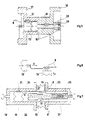
- fig. 5 to 7 show some versions for the preferred construction for the mechanic actuation of the sensors;
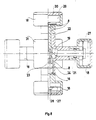
- fig. 8 shows a possible embodiment of the invention.
- In fig. 1 the outputs of the
signal transmitters 1 are connected to the input of the counter 2 - by inserting the conditionally applicable or omissible/and therefore indicated with a dotted line/state -register 5 and change-sensing circuit 4 - while the output of thecounter 2 is connected to the input of the display 3. Further inputs of the display are connected with the outputs of the conditionally containeddigital chronometer 6 and electronic chronometer 6 (indicated with dotted lines), whereas the input of the electronic chronometer and input of thecounter 2 are formed as common inputs. The cancelling push-button (clear key) 14 is connected to the null-setting inputs of thecounter 2, the state-register 5 and theelectronic chronometer 6. - As it is to be seen in fig. 2, the
signal transmitter 1 consists of the parallel-connected connection-contacts 8, one poles of which are connected to the + U supply voltage, while the other poles form the outputs of thesignal transmitter 1 via the bounce-filter circuit 9. - The embodiment according to fig. 3 comprises the serial effect-chain of the rotatable two-
circuit cross-switches 10, the input leads of which are connected to the + U and - U supply voltages, while the outputs are connected to the inputs of the static level-controlled bistabile circuit (flip-flop) 11 and one output of the latter one forms the output of thesignal transmitter 1. - With the embodiment according to fig. 4 the
electronic chronometer 6 consists of the digital stop-watch 12 and theoutput register 13; the output of the former one and the input of the latter one are interconnected. The output of theoutput register 13 forms the output of theelectronic chronometer 6. The control input of circuit is connected to the starting input of the digital stop-watch 12 as well as to the input of theoutput register 13, controlling write-in activity. Null-setting input C of the circuit is connected partly to null-setting and stopping input of the digital stop-watch 12, partly to the null-setting input of theoutput register 13. - Fig. 5 shows an embodiment, with which the
connection contact 8 is arranged in thecentral element 17 of the trademark registered «Magic Cube», together with anintermediate piece 1 with the claw-type toothing, bearing up against said contact and the rotation preventingarrester catch 21, as well as the upper end of the shank carrying the plate-centre 19 with the clawed endsurface. The plate-centre element 18 - secured by the arrester catch 21 - is arranged on said shank, the hollow of the plate-centre element 18 keeps thespring 20 and the coun-ternut 26. - As it is to be seen in fig. 6, in the transversal direction «y» and longitudinal direction «x» an
intermediate piece 15 each is bearing up against the connection-contact 8 consisting of the slanted resp. staggered overlapped pair of springs. - Fig. 7 shows an embodiment of the invention, with which in the
tubular shaft 22 having been formed in the middle of the trademark registered «Magic Cube» one by one the following components are arranged: the clawed endpart of the shank carrying the place-centre 19, theintermediate piece 16 with the double claws and secured with thearrester catch 21, theintermediate piece 24 with the handle, one half-spring of the connection-contacts 8 attached to theintermediate piece 24, thelong spring 23, as well as the protruding end of the hollow shank carrying the plate-centre 25 and secured to the intermediate 'piece 24 by means of afurther arrester catch 21, as well as the other half-springs of the connection-contacts 8 connected to said hollow shank. - The cam end of the
intermediate piece 15 each is connected loosely to theswitch contacts 8. - Fig. 8 shows a possible mode of realization. The electronic signal processing and displaying
unit 29 is arranged below thewindowed lid 30, said unit realizes the functions according to fig. 1. The connection-contacts 8 control the electronic signal processing and displayingunit 29. The connection-contact 8 having been arranged in thehollow shank 25 carrying the plate-centre forms - by the intervention of theintermediate piece 24 with the handle and the long spring 23 - the common point of the switches in thetubular axis 22. The active connection-contacts 8 of the switches are lying between the inner wall of thetubular axis 22 and the outer wall of thehollow shank 25 carrying the plate-centre and they are connected to the electronicsignal processing unit 29. - The electronic spatial logic toy containing movable elements according to the invention operates, as follows:
- The circuit arrangement according to fig. 1 operates, as follows:
- At the simplest version of the arrangement only the elements indicated with the continuous line are taking part in the operation, so one
single signal transmitter 1, thecounter 2, the display 3 and the cancelling push-button 14. Prior to beginning the game, by pressing the cancelling push-button (clear key) 14 thecounter 2 is set to null. Thereafter, upon every single step of arranging thesignal transmitter 1 sends a pulse each to thecounter 2; the pulses are counted in thecounter 2, the current digital value is displayed on the display 3, displaying thus the total number of steps, when arranging of the toy is finished. If duration of arranging is intended to be measured, the circuit arrangement must contain theelectronic chronometer 6, which can be set to zero, be stopped by means of the cancelling push-button (clear key) 14, and which is re-started from zero upon the first counting pulse; thereafter, after every single step it delivers the span of time reckoned from the first step to the very last step on its output. A possible layout of theelectronic chronometer 6 will be explained in connection with fig. 4. Thedigital chronometer 7 represents a further special unit, which indicates the actual time to the display 3. The display 3 may display simultaneously said numerical values, however, a construction is also possible, with which the date intended to be displayed may be displayed by means of selector switch, enabling a more economical way of displaying. The internal timing signal of thedigital chronometer 7 may be possibly used also for theelectronic chronometer 6, enabling a more simple construction of the circuit arrangement. This possibility is indicated by the dotted line in fig. 1, referring to the signal lead interconnecting theelectronic chronometer 6 and thedigital chronomter 7. - In case, if a plurality of
signal transmitter 1 is used, the circuit 4 for sensing the changes has to be inserted too. The task of said circuit lies in upon every change in the signal level appearing in any input channel or upon the appearance of a pulse to send an output pulse each to thecounter 2. In case, if a state-register 5 is also contained, the content of the latter one, i.e. the bit sample is a code of the type «N minus 1 », in which the single logic signal « 1 indicates the channel which was active at the last out of the input channels. Now, if the signal transmitters are alternatively activated, the content of the state-register 5 will change with every single step, while if thesame signal trasmitter 1 is actuated repeatedly, the content of the state-register 5 does not change. At the beginning of the game the state-register 5 is also set to zero by means of the cancelling push-button (clear key) 14. Thereafter, at every change of the content of the state-register 5 the circuit 4 sensing the change is sending a pulse each to thecounter 2 and theelectronic chronometer 6, that means that operation is taking place similarly, as earlier described. The only difference lies in that every repeated actuation of the toy elements belonging to the same signal transmitter 1 - no matter how many - counts as one single step. This is of importance, if the character of the game requires the application of rules of games involving this type of counting. So e.g. a counting rule may be laid for the trademark registered «Rubik's Cube», in sense of which repeated turn of the same plate by a quarter or half or a full turn is counted as one single step. As for the technical solution of thesignal transmitters 1, any miniaturized well-known sensor can be used forthis purpose, which is suitable for sensing displacements or angular displacements in discrete steps, so. e.g. electric contact, furtheron a sensor operating on optical, magnetic, inductive, capacitive etc., principle or a logical arrangement consisting of a plurality of said sensors. In practice, electric contacts can be used most economically for this purpose, however, in dependence of the structural design of the toy a satisfactory solution can be achieved by using optical switches with conductive filaments or magnetic switches containing movable ferro-magnetic shunts. - Fig. 2 shows a
signal transmitter 1 containing a plurality of electric contacts. In standstill of the toy everyconnection contact 8 is open, in course of an arranging step each one of the connection contacts closes for a short time and gives + U voltage to the input of thebounce filter 9, thereafter it interrupts again. In such a manner on the output of the bounce filter 9 a regular rectangular pulse appears which is well suitable for controlling thecounter 2. In case, if we wish to realize the logical connection according to fig. 2 e.g. with optical switches, instead of the + U supply voltage e.g. a LED light source and instead of thebounce filter 9 an electrooptical coupling element may be used. - The version according to fig. 3 operates, as follows:
- Serial effect-chain of the cross-switches 10 serving as sensors guarantees that + U supply voltage gets to one input of the flip-
flop 11, while -U supply voltage is led to the other input. In course of any arranging step one of the cross-switches 10 is turning with a quarter of a total turn, as a consequence the + U and - U voltages on the inputs of the flip-flop are interchanged, it tilts over, while thecounter 2 is counting the tilting motions. - The task of the
electronic chronometer 6 according to fig. 4 is to produce the numerical value of the span of time between the first step and the last step of arranging. At the beginning of the game the electric signal given to the input «C» setting to zero partly sets to zero the digital stop-watch 12 and stops its function, partly it sets to zero the content of theoutput register 13. Electric pulses indicating the arranging steps arrive to the input «B». Any pulse of this kind is stopping the function of the digital stop-watch 12, or if it is already going, function thereof is not at all influenced; additionaly, the same signal commands theoutput register 13 to write-in, as a consequence, it takes over the momentary numerical value of the stop-watch 12, thus on the output always the span of time can be read, which elapsed till the last arranging step. It should be mentioned that in case, if the system contains adigital chronometer 7 anyway, the internal timing pulse thereof can be used for actuating the digital stop-watch 12, as a consequence its construction becomes more simple, the more, if a commercially availabledigital chronometer 7 is applied, it can be used as a stop-watch, if it has the proper function. - With the mechanic arrangement according to fig. 5 by turning the plate-
centre element 18 by a quarter, as a consequence of the rotary motion of the shank carrying the plate-centre 19, theintermediate piece 15 with the clawed toothing - the rotation of which is hindered by the catch 21 - is displaced to the left, and the protruding cam thereof is closing the connection-contact 8 in the centre-element 17. After having finished said quarter-turn, the connection contact springs back and interrupts. - Fig. 6 shows a connection-
contact 8 which can be actuated from two directions. From the slanted resp. staggered overlapped formation it becomes obvious that it will be closed, wheter displacement is taking place in the direction «x», or in direction «y». - With the embodiment according to fig. 7, if the upper
intermediate piece 15 is moved in the direction «z», resp. the lowerintermediate piece 15 is moved in direction «y», the upper resp. the lower connection-contact 8 will close. - The
intermediate piece 16 with the double claws and prevented in rotation by thecatch 21 makes sure that either the shank carrying the plate-centre 19 on the left is turned, or the hollow shank carrying the plate-centre 25 on the right side is turned - each one separately - theintermediate piece 24 with the handle will turn in direction «x» (to the right) to such an extent that the lower connection-contact 8 is already closing, while the upper connection-contact 8 is still open. However, if both shanks are turned simultaneously, displacement of theintermediate piece 24 with the handle will be of the double extent, i.e. the structure acts as a mechanic summing unit, so the upper connection-contact 8 is also closing. - By applying the mechanic solutions according to fig. 5 to 7, furtheron by forming the electronic and displaying circuits as miniaturized integrated circuits, the invention can be applied most economically and suitably for serial production for the trademark registered «Magic Cube» of Rubik.
- In this case it seems to be expedient to arrange the integrated circuit containing the electronic units in the hollow of the plate-
centre element 18, which is connected - according to Fig. 7 - to the hollow shank carrying the plate-centre 25 on the right side of thetubular axis 22, as electric connection of the co-rotating connection-contacts 8 could be solved so in the most simple manner. Accordingly, the tubular axis according to fig. 7 ist playing a special role in the layout of the whole construction and can be considered as the preferred main axis of the toy. - If any of the plate-centre-
elements 18 with the horizontal axis - see fig. 8 - is turned, due to the paths formed on the shank carrying the plate-centre 19 and thetubular axis 22, the shank carrying the plate-centre 19 will turn axially, and closes the opposite lying switch consisting of the connection-contacts 8. Turning of the shank carrying the plate-centre 19 is promoted by thecatch 21, while the axial motion is limited by theleaf spring 27, simultanously ensuring the dilatation needed for turning the cube. The plate-centre elements 18 with the horizontal axis according to fig. 8 are closed with thelid 31. - If the upper one out of the plate-
centre elements 18 with the vertical axis according to fig. 8 is turned, the hollow shank carrying the plate-centre 25 is co-rotating, so are theintermediate piece 24 with the handle and the fixingscrew 28. Under the influence of the forced trajectories on theintermediate piece 16 with the double claws and theintermediate piece 24 with the handle the connection-contacts 8 are performing the vertical motion as to be seen in the fig. 8 and establish the connection desired. - Now, if the lower plate-
centre element 18 with the vertical axis according to fig. 8 is turned, theintermediate piece 16 with the double claws is also turning and under the influence of its own forced trajectory and that on theintermediate piece 24 it lifts theintermediate piece 24 with the handle and closes the connection-contacts 8. In this case dilatation needed for turning the vertical axis is assured by theleaf spring 27 to be found in the lower plate-centre element 18 with the vertical axis according to fig. 8. - The advantage of the invention lies in that by the aid of the relatively simple, miniaturized structural elements, being well suitable for mass production, the toys with the movable and/or rotatable elements can be brought to a far higher level, as both counting of steps and accurate measuring of arranging time - even with breaking down to hundredth seconds - are successfully solved, consequently, requirements in respectto applicability for competitions are also met. A further accessory advantageous feature lies in that in case of application of the
digital chronometer 7 according to fig. 1, the toy - when out of use - can be used as a digital table clock with pleasant aesthetic appearance. The invention can be preferably applied first of all for the further-development of mechanic toys which unit aesthetic appearance and complexity of toys with a puzzle character on a high level, as e.g. the well known trademark registered «Magic Cube» of Rubik or «Rubik's Cube».
Claims (8)
Priority Applications (1)
| Application Number | Priority Date | Filing Date | Title |
|---|---|---|---|
| AT86901982T ATE43972T1 (en) | 1985-03-04 | 1986-03-04 | ELECTRONIC LOGICAL SPACE TOY WITH MOVABLE AND/OR ROTATING ELEMENTS. |
Applications Claiming Priority (2)
| Application Number | Priority Date | Filing Date | Title |
|---|---|---|---|
| HU85784A HU194743B (en) | 1985-03-04 | 1985-03-04 | Electronic logic toy containing movable elements |
| HU78485 | 1985-03-04 |
Publications (2)
| Publication Number | Publication Date |
|---|---|
| EP0214266A1 EP0214266A1 (en) | 1987-03-18 |
| EP0214266B1 true EP0214266B1 (en) | 1989-06-14 |
Family
ID=10951330
Family Applications (1)
| Application Number | Title | Priority Date | Filing Date |
|---|---|---|---|
| EP86901982A Expired EP0214266B1 (en) | 1985-03-04 | 1986-03-04 | Electronic spatial logical toy containing movable and/or rotatable elements |
Country Status (5)
| Country | Link |
|---|---|
| US (1) | US4817952A (en) |
| EP (1) | EP0214266B1 (en) |
| DE (1) | DE3663886D1 (en) |
| HU (1) | HU194743B (en) |
| WO (1) | WO1986005111A1 (en) |
Families Citing this family (34)
| Publication number | Priority date | Publication date | Assignee | Title |
|---|---|---|---|---|
| US5271688A (en) * | 1992-08-28 | 1993-12-21 | Famwealth International Inc. | Joint for magic square central bearing structure |
| US5509656A (en) * | 1993-10-25 | 1996-04-23 | Image Design & Marketing | Electronic maze puzzle |
| US6460849B1 (en) | 1999-03-16 | 2002-10-08 | Jeffrey W. Bean | Rotating ring game |
| US7559837B1 (en) | 2000-09-01 | 2009-07-14 | Igt | Video gaming system with wild card system and bonus system |
| US6394903B1 (en) * | 2001-01-23 | 2002-05-28 | Star H.K. Electronic Ltd. | Toy dice |
| US7258611B2 (en) * | 2002-02-28 | 2007-08-21 | Igt | Gaming device having free game bonus with a changing multiplier |
| US7252591B2 (en) * | 2002-07-31 | 2007-08-07 | Igt | Gaming device having symbol stacks |
| US7666083B2 (en) * | 2002-09-11 | 2010-02-23 | Igt | Gaming device having a free spin game including an accumulated modifier |
| US6960134B2 (en) * | 2002-09-12 | 2005-11-01 | Igt | Alternative bonus games associated with slot machine |
| US7022036B2 (en) * | 2003-05-21 | 2006-04-04 | Prototoy Llc | Electronic throw-and-catch game |
| US7862415B1 (en) * | 2005-01-25 | 2011-01-04 | Ghaly Nabil N | Method and apparatus for electronic puzzle device |
| CN101291711B (en) * | 2005-10-20 | 2011-11-23 | 皇家飞利浦电子股份有限公司 | Game with programmable light emitting segments |
| US7644924B2 (en) | 2006-05-13 | 2010-01-12 | Jay Horowitz | Three dimensional sudoku cube puzzle and method |
| US8137179B2 (en) | 2006-11-08 | 2012-03-20 | Igt | Gaming device having expanding and rolling wild symbols |
| US20080230988A1 (en) * | 2007-03-23 | 2008-09-25 | Maxime Paquette | Three-dimensional logical puzzles |
| US20090091570A1 (en) * | 2007-10-03 | 2009-04-09 | Maxime Paquette | Dividing method for three-dimensional logical puzzles |
| US20090091080A1 (en) * | 2007-10-03 | 2009-04-09 | Maxime Paquette | Dividing method for three-dimensional logical puzzles |
| US20090127784A1 (en) * | 2007-11-16 | 2009-05-21 | Maxime Paquette | Keyed access to hollow three-dimensional puzzles |
| US20090127783A1 (en) * | 2007-11-16 | 2009-05-21 | Maxime Paquette | Shiftable cubic puzzle with superimposed slidable elements |
| US20090218765A1 (en) * | 2008-03-02 | 2009-09-03 | Maxime Paquette | Odd-shaped three-dimensional logical puzzles |
| US8408990B2 (en) | 2008-11-14 | 2013-04-02 | Igt | Gaming system, gaming device, and method for providing benefit in a future play of a wagering game |
| WO2010120780A1 (en) * | 2009-04-13 | 2010-10-21 | Sg Labs, Llc | Hand-manipulable interface methods and systems |
| US8387984B2 (en) * | 2010-04-07 | 2013-03-05 | Bahry Uri Management Ltd. | Manipulative three-dimensional puzzle |
| US9293014B2 (en) | 2012-03-12 | 2016-03-22 | Igt | Gaming device having persistently extending wild symbols |
| US9098973B2 (en) | 2013-03-08 | 2015-08-04 | Igt | Gaming system and method for providing a game including roaming wild symbols |
| US9098847B2 (en) | 2013-03-08 | 2015-08-04 | Igt | Gaming system and method for providing a game including roaming wild symbols |
| CN106110651B (en) * | 2016-08-12 | 2017-11-21 | 佛山市计客创新科技有限公司 | Intelligent magic cube and its sensing axle centre structure, the clocking method used |
| TW201806651A (en) * | 2016-08-19 | 2018-03-01 | 雷虎科技股份有限公司 | Interactive magic cube using speech control to adjust an interactive module |
| CN108479055A (en) * | 2018-05-07 | 2018-09-04 | 南月(广州)机器人科技有限公司 | A kind of magic square monitoring rotary state |
| CN108525283A (en) * | 2018-06-05 | 2018-09-14 | 佛山市计客创新科技有限公司 | Intelligent magic cube and its sensor and axle centre structure |
| CN109675297A (en) * | 2019-01-18 | 2019-04-26 | 佛山市计客创新科技有限公司 | Intelligent axis, Intelligent magic cube and its clocking method |
| CN110180165B (en) * | 2019-03-27 | 2024-09-27 | 佛山市计客创新科技有限公司 | Intelligent center shaft, intelligent magic cube and intelligent magic cube monitoring method |
| CN110368669B (en) | 2019-07-03 | 2024-02-23 | 佛山市计客创新科技有限公司 | Intelligent magic cube, sensor used by intelligent magic cube, intelligent center shaft and monitoring method |
| KR102545603B1 (en) * | 2020-12-11 | 2023-06-22 | 옵토로직스주식회사 | Smart cube |
Family Cites Families (4)
| Publication number | Priority date | Publication date | Assignee | Title |
|---|---|---|---|---|
| US4248422A (en) * | 1979-05-03 | 1981-02-03 | Gene Messina | Electronic maze game |
| US4323242A (en) * | 1980-09-23 | 1982-04-06 | Rosenfeld Peter E | Electronic maze game |
| HU180387B (en) * | 1980-10-28 | 1983-02-28 | Rubik Erno | Spatial logic toy |
| US4463946A (en) * | 1981-12-28 | 1984-08-07 | Wallace Lynn A | Fitness evaluation apparatus |
-
1985
- 1985-03-04 HU HU85784A patent/HU194743B/en not_active IP Right Cessation
-
1986
- 1986-03-04 DE DE8686901982T patent/DE3663886D1/en not_active Expired
- 1986-03-04 US US06/939,045 patent/US4817952A/en not_active Expired - Fee Related
- 1986-03-04 EP EP86901982A patent/EP0214266B1/en not_active Expired
- 1986-03-04 WO PCT/HU1986/000012 patent/WO1986005111A1/en not_active Ceased
Also Published As
| Publication number | Publication date |
|---|---|
| EP0214266A1 (en) | 1987-03-18 |
| US4817952A (en) | 1989-04-04 |
| HU194743B (en) | 1988-03-28 |
| WO1986005111A1 (en) | 1986-09-12 |
| HUT43500A (en) | 1987-11-30 |
| DE3663886D1 (en) | 1989-07-20 |
Similar Documents
| Publication | Publication Date | Title |
|---|---|---|
| US4817952A (en) | Electronic spatial logical toy containing movable and/or rotatable elements | |
| US4858931A (en) | Electronic dice | |
| US4216965A (en) | Microcomputer controlled electronic game apparatus | |
| US5134565A (en) | Electronic scoring device for tennis competitions | |
| EP0332451A2 (en) | Electronic puzzle | |
| US5550884A (en) | "Golf Counter" device and watch combined with such a device | |
| US4119838A (en) | Electronic score-keeper for table tennis | |
| US4474481A (en) | Granule flow timer | |
| US4681463A (en) | Differential timer | |
| CA2048893C (en) | Game score indicator | |
| CA1270866A (en) | Electronic spatial logical toy containing movable and/or rotatable elements | |
| US4325551A (en) | Electronically controlled game apparatus with playing array positions actuatable by a player controlled movable object | |
| JPH01171588A (en) | Reasoning puzzle | |
| JPS62502592A (en) | Electronic spatial logic toy with movable and/or rotatable components | |
| GB2499584A (en) | Puzzle with timer | |
| US3823943A (en) | Parlour game | |
| US3989242A (en) | Game of manual dexterity | |
| SU1487915A1 (en) | ELECTRONIC GAME | |
| SU1531066A1 (en) | Electronic chess clock | |
| WO1992019338A1 (en) | Puzzle device | |
| JPS6031501B2 (en) | Control device for game machines | |
| SU1466770A1 (en) | Control device for electronic game | |
| SU1219103A1 (en) | Electronic game | |
| SU1718997A1 (en) | Electronic game control device | |
| SU1526708A1 (en) | Apparatus for game |
Legal Events
| Date | Code | Title | Description |
|---|---|---|---|
| PUAI | Public reference made under article 153(3) epc to a published international application that has entered the european phase |
Free format text: ORIGINAL CODE: 0009012 |
|
| AK | Designated contracting states |
Kind code of ref document: A1 Designated state(s): AT BE CH DE FR GB IT LI LU NL SE |
|
| 17P | Request for examination filed |
Effective date: 19870223 |
|
| 17Q | First examination report despatched |
Effective date: 19870914 |
|
| RAP3 | Party data changed (applicant data changed or rights of an application transferred) |
Owner name: RUBIK STUDIO MUESZAKI FEJLESZTOE KISSZOEVETKEZET |
|
| GRAA | (expected) grant |
Free format text: ORIGINAL CODE: 0009210 |
|
| AK | Designated contracting states |
Kind code of ref document: B1 Designated state(s): AT BE CH DE FR GB IT LI LU NL SE |
|
| REF | Corresponds to: |
Ref document number: 43972 Country of ref document: AT Date of ref document: 19890615 Kind code of ref document: T |
|
| REF | Corresponds to: |
Ref document number: 3663886 Country of ref document: DE Date of ref document: 19890720 |
|
| ET | Fr: translation filed | ||
| ITF | It: translation for a ep patent filed | ||
| PLBE | No opposition filed within time limit |
Free format text: ORIGINAL CODE: 0009261 |
|
| STAA | Information on the status of an ep patent application or granted ep patent |
Free format text: STATUS: NO OPPOSITION FILED WITHIN TIME LIMIT |
|
| 26N | No opposition filed | ||
| PGFP | Annual fee paid to national office [announced via postgrant information from national office to epo] |
Ref country code: SE Payment date: 19910315 Year of fee payment: 6 |
|
| PGFP | Annual fee paid to national office [announced via postgrant information from national office to epo] |
Ref country code: FR Payment date: 19910319 Year of fee payment: 6 |
|
| PGFP | Annual fee paid to national office [announced via postgrant information from national office to epo] |
Ref country code: AT Payment date: 19910321 Year of fee payment: 6 |
|
| PGFP | Annual fee paid to national office [announced via postgrant information from national office to epo] |
Ref country code: GB Payment date: 19910326 Year of fee payment: 6 Ref country code: CH Payment date: 19910326 Year of fee payment: 6 |
|
| PGFP | Annual fee paid to national office [announced via postgrant information from national office to epo] |
Ref country code: DE Payment date: 19910327 Year of fee payment: 6 |
|
| PGFP | Annual fee paid to national office [announced via postgrant information from national office to epo] |
Ref country code: LU Payment date: 19910328 Year of fee payment: 6 |
|
| ITTA | It: last paid annual fee | ||
| PGFP | Annual fee paid to national office [announced via postgrant information from national office to epo] |
Ref country code: NL Payment date: 19910331 Year of fee payment: 6 |
|
| PGFP | Annual fee paid to national office [announced via postgrant information from national office to epo] |
Ref country code: BE Payment date: 19910410 Year of fee payment: 6 |
|
| EPTA | Lu: last paid annual fee | ||
| PG25 | Lapsed in a contracting state [announced via postgrant information from national office to epo] |
Ref country code: LU Free format text: LAPSE BECAUSE OF NON-PAYMENT OF DUE FEES Effective date: 19920304 Ref country code: GB Effective date: 19920304 Ref country code: AT Effective date: 19920304 |
|
| PG25 | Lapsed in a contracting state [announced via postgrant information from national office to epo] |
Ref country code: SE Effective date: 19920305 |
|
| PG25 | Lapsed in a contracting state [announced via postgrant information from national office to epo] |
Ref country code: LI Effective date: 19920331 Ref country code: CH Effective date: 19920331 Ref country code: BE Effective date: 19920331 |
|
| BERE | Be: lapsed |
Owner name: RUBIK STUDIO MUSZAKI FEJLESZTO KISSZOVETKEZET Effective date: 19920331 |
|
| PG25 | Lapsed in a contracting state [announced via postgrant information from national office to epo] |
Ref country code: NL Effective date: 19921001 |
|
| GBPC | Gb: european patent ceased through non-payment of renewal fee | ||
| NLV4 | Nl: lapsed or anulled due to non-payment of the annual fee | ||
| PG25 | Lapsed in a contracting state [announced via postgrant information from national office to epo] |
Ref country code: FR Effective date: 19921130 |
|
| REG | Reference to a national code |
Ref country code: CH Ref legal event code: PL |
|
| PG25 | Lapsed in a contracting state [announced via postgrant information from national office to epo] |
Ref country code: DE Effective date: 19921201 |
|
| REG | Reference to a national code |
Ref country code: FR Ref legal event code: ST |
|
| EUG | Se: european patent has lapsed |
Ref document number: 86901982.8 Effective date: 19921005 |
|
| PG25 | Lapsed in a contracting state [announced via postgrant information from national office to epo] |
Ref country code: IT Free format text: LAPSE BECAUSE OF NON-PAYMENT OF DUE FEES;WARNING: LAPSES OF ITALIAN PATENTS WITH EFFECTIVE DATE BEFORE 2007 MAY HAVE OCCURRED AT ANY TIME BEFORE 2007. THE CORRECT EFFECTIVE DATE MAY BE DIFFERENT FROM THE ONE RECORDED. Effective date: 20050304 |