EP0213089B1 - Resilient support with variable flexibility, particularly for motor vehicle suspensions - Google Patents
Resilient support with variable flexibility, particularly for motor vehicle suspensions Download PDFInfo
- Publication number
- EP0213089B1 EP0213089B1 EP86830210A EP86830210A EP0213089B1 EP 0213089 B1 EP0213089 B1 EP 0213089B1 EP 86830210 A EP86830210 A EP 86830210A EP 86830210 A EP86830210 A EP 86830210A EP 0213089 B1 EP0213089 B1 EP 0213089B1
- Authority
- EP
- European Patent Office
- Prior art keywords
- parts
- resilient support
- metal member
- band
- resilient
- Prior art date
- Legal status (The legal status is an assumption and is not a legal conclusion. Google has not performed a legal analysis and makes no representation as to the accuracy of the status listed.)
- Expired
Links
- 239000000725 suspension Substances 0.000 title description 6
- 239000002184 metal Substances 0.000 claims description 23
- 239000013536 elastomeric material Substances 0.000 claims description 3
- 238000006073 displacement reaction Methods 0.000 description 2
- 238000010276 construction Methods 0.000 description 1
Images
Classifications
-
- F—MECHANICAL ENGINEERING; LIGHTING; HEATING; WEAPONS; BLASTING
- F16—ENGINEERING ELEMENTS AND UNITS; GENERAL MEASURES FOR PRODUCING AND MAINTAINING EFFECTIVE FUNCTIONING OF MACHINES OR INSTALLATIONS; THERMAL INSULATION IN GENERAL
- F16F—SPRINGS; SHOCK-ABSORBERS; MEANS FOR DAMPING VIBRATION
- F16F1/00—Springs
- F16F1/36—Springs made of rubber or other material having high internal friction, e.g. thermoplastic elastomers
- F16F1/371—Springs made of rubber or other material having high internal friction, e.g. thermoplastic elastomers characterised by inserts or auxiliary extension or exterior elements, e.g. for rigidification
- F16F1/3713—Springs made of rubber or other material having high internal friction, e.g. thermoplastic elastomers characterised by inserts or auxiliary extension or exterior elements, e.g. for rigidification with external elements passively influencing spring stiffness, e.g. rings or hoops
-
- B—PERFORMING OPERATIONS; TRANSPORTING
- B60—VEHICLES IN GENERAL
- B60G—VEHICLE SUSPENSION ARRANGEMENTS
- B60G9/00—Resilient suspensions of a rigid axle or axle housing for two or more wheels
- B60G9/02—Resilient suspensions of a rigid axle or axle housing for two or more wheels the axle or housing being pivotally mounted on the vehicle, e.g. the pivotal axis being parallel to the longitudinal axis of the vehicle
- B60G9/027—Resilient suspensions of a rigid axle or axle housing for two or more wheels the axle or housing being pivotally mounted on the vehicle, e.g. the pivotal axis being parallel to the longitudinal axis of the vehicle the axle having either a triangular, a "T" or "U" shape and being directly articulated with the chassis only by its middle apex, e.g. De Dion suspension
Definitions
- the present invention relates to a resilient support for connecting a movable structure to a fixed support structure, of the known type comprising:
- the object of the invention is to provide a resilient support of the type specified above, which can be used, for example, to connect the central part of an axle to the body of a motor vehicle, and which has a simple, reliable and economical structure.
- the present invention provides a resilient support of the type specified above, characterised in that the flexible band has a first rectilinear part fixed to the first metal member and a second rectilinear part fixed to the second metal member and disposed parallel to and spaced from the first part, and in that the resilient means are interposed in a compressed condition between the two parts so as to put under tension third and fourth parts of the band which join the ends of the first and second parts together.
- the second part is shorter than the first part, whereby the flexible band takes up a trapezoidal configuration in which the two bases are constituted by the first and second parts of the band and in which the two oblique sides are constituted by the third and fourth parts of the band.
- the resilient means are constituted by a body of elastomeric material.
- the resilient support is adapted to withstand, without yielding, a load which tends to move the movable member relative to the support structure in a direction parallel to that of the second part of the flexible band, as long as this load is kept below a predetermined threshold value. Above this value, one of the two oblique sides of the band ceases to work under tension and collapses, allowing relative movement betweem the two metal members of the support.
- the axle 2 has essentially a V-shape disposed in a horizontal plane so that its central part (indicated 4) is displaced towards the front of the motor vehicle (the direction of movement of the vehicle being indicated by the arrow A in Figures 1 and 2).
- the central part 4 of the axle 2 is articulated to the body of the motor vehicle (indicated 6) about a transverse axis 7.
- a resilient support 5 (illustrated schematically in Figures 1 and 2) is also interposed in this connection.
- the axle 2 is also connected to the body 6 by two torque arms 8 each of which has a front end articulated to the body 6 and a rear end articulated to the axle 2 adjacent a respective end portion thereof.
- the two front ends of the torque arms 8 are aligned along a transverse axis coincident with the axis 7.
- the resilient means of the suspension are constituted by a pair of helical springs interposed between the end portions of the axle and the body. In the drawings, the points of application of the springs are indicated 9.
- the two torque arms 8 are disposed in directions which converge on each other towards the rear of the motor vehicle.
- the resilient support 5 is adapted to allow small movements of the axle relative to the body in a transverse direction and small rotational movements of the axle in the horizontal plane.
- One embodiment of the resilient support useable for this purpose is illustrated in the document EP-A-0 140 845.
- the present invention proposes a new type of resilient support useable for the same purpose, and which has particular characteristics of simplicity and reliability.
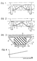
- Figure 3 illustrates schematically the resilient support according to the invention. It includes a first metal member 10 for fixing to the body of the motor vehicle and a second metal member 11 for fixing to the central part 4 of the axle 2.
- the two metal members 10, 11 are connected by a flexible band 12, for example of rubber webbing, which has a first part 13 fixed to the metal member 10 and a second part 14 fixed to the metal member 11.
- a body 15 of elastomeric material is interposed in a compressed condition between the two metal members 11,10 so as to put under tension the two parts 16, 17 of the band 12 which join the ends of the parts 13, 14 together.
- the flexible band 12 is in the form of a closed ring and thus assumes a trapezoidal configuration in which the bases are constituted by the two parallel parts 13, 14 of the band while the two oblique sides are constituted by the two parts 16,17 of the band.
- the trapezoidal configuration arises from the fact that the part 14 fixed to the metal member 11 is shorter than the part 13 fixed to the metal member 10.
- the resilient support 5 withstands a load P acting on the metal member 11 and directed parallel to the part 14 without yielding, as long as this load is kept below a predetermined threshold value P o .
- a predetermined threshold value P o a predetermined threshold value
- one of the two oblique parts 16,17 ofthe flexible band (the right-hand part or the left-hand part, respectively, according to whether the load P acts towards the right or towards the left with reference to Figure 3) ceases to work under tension and collapses, allowing the displacement of the metal member 11 relative to the metal member 13.
- the graph of Figure 4 illustrates the displacement obtained as a function of the load P. As is clear from the graph, the movement is zero as long as the value of the load P does not surpass the threshold value P o .
- the resilient support according to the invention has particular advantages from the point of view of simplicity, reliability and silence of operation.
- the support according to the invention is also useable, of course, in different applications from that described above by way of example.
Landscapes
- Engineering & Computer Science (AREA)
- General Engineering & Computer Science (AREA)
- Mechanical Engineering (AREA)
- Vibration Prevention Devices (AREA)
- Optical Communication System (AREA)
- Springs (AREA)
Applications Claiming Priority (2)
| Application Number | Priority Date | Filing Date | Title |
|---|---|---|---|
| IT6772085 | 1985-08-09 | ||
| IT67720/85A IT1183919B (it) | 1985-08-09 | 1985-08-09 | Sopporto elastico a flessibilita variabile particolarmente per sospensioni di autoveicoli |
Publications (2)
| Publication Number | Publication Date |
|---|---|
| EP0213089A1 EP0213089A1 (en) | 1987-03-04 |
| EP0213089B1 true EP0213089B1 (en) | 1988-12-07 |
Family
ID=11304771
Family Applications (1)
| Application Number | Title | Priority Date | Filing Date |
|---|---|---|---|
| EP86830210A Expired EP0213089B1 (en) | 1985-08-09 | 1986-07-17 | Resilient support with variable flexibility, particularly for motor vehicle suspensions |
Country Status (5)
| Country | Link |
|---|---|
| EP (1) | EP0213089B1 (es) |
| BR (1) | BR8603839A (es) |
| DE (1) | DE3661347D1 (es) |
| ES (1) | ES296809Y (es) |
| IT (1) | IT1183919B (es) |
Families Citing this family (5)
| Publication number | Priority date | Publication date | Assignee | Title |
|---|---|---|---|---|
| GB2258850B (en) * | 1990-05-18 | 1993-06-30 | Phoenix Truck & Trailer Equipm | Axle beam |
| GB9011167D0 (en) * | 1990-05-18 | 1990-07-04 | Pheonix Truck & Trailer Equipm | Axle beam |
| FR2677724B1 (fr) * | 1991-06-11 | 1993-10-08 | Hutchinson | Perfectionnements aux anneaux limiteurs des supports elastiques et a leurs procedes de fabrication. |
| DE10029536A1 (de) | 2000-06-15 | 2001-12-20 | Bosch Gmbh Robert | Handwerkzeugmaschine mit zumindest einem Handgriff |
| DE202009005230U1 (de) * | 2009-09-04 | 2010-10-21 | Froli Kunststoffwerk Heinrich Fromme Ohg | Vorspanneinrichtung für ein Federkernelement |
Family Cites Families (8)
| Publication number | Priority date | Publication date | Assignee | Title |
|---|---|---|---|---|
| US1703297A (en) * | 1925-01-07 | 1929-02-26 | Gen Motors Res Corp | Resilient connecter |
| US1739025A (en) * | 1927-03-29 | 1929-12-10 | Inland Mfg Co | Spring shackle |
| US3081993A (en) * | 1960-12-12 | 1963-03-19 | Lord Mfg Co | Resilient mounting |
| DE1906804U (de) * | 1963-06-28 | 1964-12-17 | Metzeler Ag | Elastischer aufhaenger. |
| FR1544131A (fr) * | 1967-09-19 | 1968-10-31 | Citroen Sa Andre | Dispositif de liaison entre caisse et châssis de véhicule |
| US4006892A (en) * | 1975-12-15 | 1977-02-08 | Lord Corporation | Compression mounting |
| FR2340834A1 (fr) * | 1976-02-16 | 1977-09-09 | Renault | Suspension pour bloc-moteurs |
| IT1167346B (it) * | 1983-10-19 | 1987-05-13 | Fiat Auto Spa | Perfezionamenti alle sospensioni per autoveicoli |
-
1985
- 1985-08-09 IT IT67720/85A patent/IT1183919B/it active
-
1986
- 1986-06-24 ES ES1986296809U patent/ES296809Y/es not_active Expired
- 1986-07-17 EP EP86830210A patent/EP0213089B1/en not_active Expired
- 1986-07-17 DE DE8686830210T patent/DE3661347D1/de not_active Expired
- 1986-08-07 BR BR8603839A patent/BR8603839A/pt not_active IP Right Cessation
Also Published As
| Publication number | Publication date |
|---|---|
| EP0213089A1 (en) | 1987-03-04 |
| DE3661347D1 (en) | 1989-01-12 |
| ES296809U (es) | 1988-01-16 |
| IT1183919B (it) | 1987-10-22 |
| IT8567720A0 (it) | 1985-08-09 |
| BR8603839A (pt) | 1987-03-24 |
| ES296809Y (es) | 1988-09-16 |
Similar Documents
| Publication | Publication Date | Title |
|---|---|---|
| CA1297506C (en) | Vehicle suspension system | |
| EP0682604B1 (en) | Suspension system for vehicle | |
| EP0897339B1 (en) | Suspensions system with laminated beam | |
| CA1132163A (en) | Axle suspension system | |
| US4779894A (en) | Vehicle suspension | |
| EP0933241B1 (en) | Stabiliser | |
| EP0245307B1 (en) | Ground engaging surface for endless tracks, wheels and tyres | |
| US6099005A (en) | Rear suspension system of automobile discriminative of road irregularities and wheel braking | |
| JP2825808B2 (ja) | 自動車のリヤサスペンシヨン装置 | |
| US4168086A (en) | Radius arm support for a driving axle | |
| EP1315918B1 (en) | Pivot bearing | |
| EP0454994B1 (en) | Suspension system of a vehicle | |
| EP0213089B1 (en) | Resilient support with variable flexibility, particularly for motor vehicle suspensions | |
| EP0323414B1 (en) | Rear suspension for motor vehicles, of the type with independent wheels and longitudinal arms | |
| EP0149262A2 (en) | Suspension for motor vehicles with elements having a different degree of elasticity | |
| US3497235A (en) | Motor vehicle suspension | |
| EP0198313A2 (en) | Frame type flexible axle suspension system | |
| US5362091A (en) | Rear suspension for vehicle | |
| EP0853011B1 (en) | Leaf spring stabiliser | |
| US6250660B1 (en) | Camber angle control suspension system | |
| US4029338A (en) | Twin trailing link rear suspension system | |
| EP0506141A1 (en) | Suspension mechanism for vehicles | |
| EP0287094B1 (en) | Automobile rear suspension structure | |
| EP0453795B1 (en) | Suspension system of a vehicle | |
| US4813695A (en) | Multi-axle vehicle suspension |
Legal Events
| Date | Code | Title | Description |
|---|---|---|---|
| PUAI | Public reference made under article 153(3) epc to a published international application that has entered the european phase |
Free format text: ORIGINAL CODE: 0009012 |
|
| AK | Designated contracting states |
Kind code of ref document: A1 Designated state(s): DE FR GB SE |
|
| 17P | Request for examination filed |
Effective date: 19870114 |
|
| 17Q | First examination report despatched |
Effective date: 19880226 |
|
| GRAA | (expected) grant |
Free format text: ORIGINAL CODE: 0009210 |
|
| AK | Designated contracting states |
Kind code of ref document: B1 Designated state(s): DE FR GB SE |
|
| REF | Corresponds to: |
Ref document number: 3661347 Country of ref document: DE Date of ref document: 19890112 |
|
| ET | Fr: translation filed | ||
| PLBE | No opposition filed within time limit |
Free format text: ORIGINAL CODE: 0009261 |
|
| STAA | Information on the status of an ep patent application or granted ep patent |
Free format text: STATUS: NO OPPOSITION FILED WITHIN TIME LIMIT |
|
| 26N | No opposition filed | ||
| PGFP | Annual fee paid to national office [announced via postgrant information from national office to epo] |
Ref country code: GB Payment date: 19930615 Year of fee payment: 8 |
|
| PGFP | Annual fee paid to national office [announced via postgrant information from national office to epo] |
Ref country code: DE Payment date: 19930621 Year of fee payment: 8 |
|
| PGFP | Annual fee paid to national office [announced via postgrant information from national office to epo] |
Ref country code: SE Payment date: 19930623 Year of fee payment: 8 |
|
| PGFP | Annual fee paid to national office [announced via postgrant information from national office to epo] |
Ref country code: FR Payment date: 19930730 Year of fee payment: 8 |
|
| PG25 | Lapsed in a contracting state [announced via postgrant information from national office to epo] |
Ref country code: GB Effective date: 19940717 |
|
| PG25 | Lapsed in a contracting state [announced via postgrant information from national office to epo] |
Ref country code: SE Effective date: 19940718 |
|
| EUG | Se: european patent has lapsed |
Ref document number: 86830210.0 Effective date: 19950210 |
|
| GBPC | Gb: european patent ceased through non-payment of renewal fee |
Effective date: 19940717 |
|
| PG25 | Lapsed in a contracting state [announced via postgrant information from national office to epo] |
Ref country code: FR Effective date: 19950331 |
|
| PG25 | Lapsed in a contracting state [announced via postgrant information from national office to epo] |
Ref country code: DE Effective date: 19950401 |
|
| EUG | Se: european patent has lapsed |
Ref document number: 86830210.0 |
|
| REG | Reference to a national code |
Ref country code: FR Ref legal event code: ST |