EP0212261A1 - Système de distribution et de communication à large bande - Google Patents
Système de distribution et de communication à large bande Download PDFInfo
- Publication number
- EP0212261A1 EP0212261A1 EP86109797A EP86109797A EP0212261A1 EP 0212261 A1 EP0212261 A1 EP 0212261A1 EP 86109797 A EP86109797 A EP 86109797A EP 86109797 A EP86109797 A EP 86109797A EP 0212261 A1 EP0212261 A1 EP 0212261A1
- Authority
- EP
- European Patent Office
- Prior art keywords
- broadband
- broadband signals
- signals
- signal
- communication system
- Prior art date
- Legal status (The legal status is an assumption and is not a legal conclusion. Google has not performed a legal analysis and makes no representation as to the accuracy of the status listed.)
- Granted
Links
- 238000004891 communication Methods 0.000 title claims abstract description 11
- 230000005540 biological transmission Effects 0.000 description 11
- 238000000034 method Methods 0.000 description 5
- 230000001360 synchronised effect Effects 0.000 description 5
- 230000015572 biosynthetic process Effects 0.000 description 4
- 239000004020 conductor Substances 0.000 description 4
- 239000002131 composite material Substances 0.000 description 3
- 238000011084 recovery Methods 0.000 description 3
- RYGMFSIKBFXOCR-UHFFFAOYSA-N Copper Chemical compound [Cu] RYGMFSIKBFXOCR-UHFFFAOYSA-N 0.000 description 2
- 229910052802 copper Inorganic materials 0.000 description 2
- 239000010949 copper Substances 0.000 description 2
- 239000000654 additive Substances 0.000 description 1
- 230000000712 assembly Effects 0.000 description 1
- 238000000429 assembly Methods 0.000 description 1
- 238000010276 construction Methods 0.000 description 1
- 239000000284 extract Substances 0.000 description 1
- 239000000835 fiber Substances 0.000 description 1
- 239000003365 glass fiber Substances 0.000 description 1
- 239000000463 material Substances 0.000 description 1
- 239000000203 mixture Substances 0.000 description 1
- 230000000717 retained effect Effects 0.000 description 1
- 239000007787 solid Substances 0.000 description 1
Images


Classifications
-
- H—ELECTRICITY
- H04—ELECTRIC COMMUNICATION TECHNIQUE
- H04Q—SELECTING
- H04Q11/00—Selecting arrangements for multiplex systems
- H04Q11/04—Selecting arrangements for multiplex systems for time-division multiplexing
- H04Q11/0428—Integrated services digital network, i.e. systems for transmission of different types of digitised signals, e.g. speech, data, telecentral, television signals
- H04Q11/0478—Provisions for broadband connections
-
- H—ELECTRICITY
- H04—ELECTRIC COMMUNICATION TECHNIQUE
- H04H—BROADCAST COMMUNICATION
- H04H20/00—Arrangements for broadcast or for distribution combined with broadcast
- H04H20/28—Arrangements for simultaneous broadcast of plural pieces of information
-
- H—ELECTRICITY
- H04—ELECTRIC COMMUNICATION TECHNIQUE
- H04H—BROADCAST COMMUNICATION
- H04H20/00—Arrangements for broadcast or for distribution combined with broadcast
- H04H20/65—Arrangements characterised by transmission systems for broadcast
- H04H20/76—Wired systems
- H04H20/77—Wired systems using carrier waves
- H04H20/78—CATV [Community Antenna Television] systems
-
- H—ELECTRICITY
- H04—ELECTRIC COMMUNICATION TECHNIQUE
- H04N—PICTORIAL COMMUNICATION, e.g. TELEVISION
- H04N21/00—Selective content distribution, e.g. interactive television or video on demand [VOD]
- H04N21/20—Servers specifically adapted for the distribution of content, e.g. VOD servers; Operations thereof
- H04N21/23—Processing of content or additional data; Elementary server operations; Server middleware
- H04N21/236—Assembling of a multiplex stream, e.g. transport stream, by combining a video stream with other content or additional data, e.g. inserting a URL [Uniform Resource Locator] into a video stream, multiplexing software data into a video stream; Remultiplexing of multiplex streams; Insertion of stuffing bits into the multiplex stream, e.g. to obtain a constant bit-rate; Assembling of a packetised elementary stream
- H04N21/2365—Multiplexing of several video streams
-
- H—ELECTRICITY
- H04—ELECTRIC COMMUNICATION TECHNIQUE
- H04N—PICTORIAL COMMUNICATION, e.g. TELEVISION
- H04N21/00—Selective content distribution, e.g. interactive television or video on demand [VOD]
- H04N21/40—Client devices specifically adapted for the reception of or interaction with content, e.g. set-top-box [STB]; Operations thereof
- H04N21/43—Processing of content or additional data, e.g. demultiplexing additional data from a digital video stream; Elementary client operations, e.g. monitoring of home network or synchronising decoder's clock; Client middleware
- H04N21/434—Disassembling of a multiplex stream, e.g. demultiplexing audio and video streams, extraction of additional data from a video stream; Remultiplexing of multiplex streams; Extraction or processing of SI; Disassembling of packetised elementary stream
- H04N21/4347—Demultiplexing of several video streams
-
- H—ELECTRICITY
- H04—ELECTRIC COMMUNICATION TECHNIQUE
- H04J—MULTIPLEX COMMUNICATION
- H04J2203/00—Aspects of optical multiplex systems other than those covered by H04J14/05 and H04J14/07
- H04J2203/0001—Provisions for broadband connections in integrated services digital network using frames of the Optical Transport Network [OTN] or using synchronous transfer mode [STM], e.g. SONET, SDH
- H04J2203/0089—Multiplexing, e.g. coding, scrambling, SONET
Definitions
- the invention relates to a broadband distribution communication system according to the preamble of claim 1.
- a broadband distribution communication system is described in the journal "Schrichtsdorf der Deutschen Farbpost” Edition B, Fernmeldecher, Jg. 35/1982, No. 3, pages 139 to 164 .
- section 4.1 of the above-mentioned article it is described that the television programs of the broadcasters and the local program providers are sent to a central office (broadcaster receiving station) as broadband signals.
- the sources of these television programs or broadband signals are therefore the studios of the broadcasters and the local program providers.
- the television programs are forwarded to the head office (radio reception center) in the same signal form in which they are also broadcast for direct wireless reception by participants.
- head office radio reception center
- bandwidth-reducing modulation methods such as NTSC, PAL, SECAM applied. Such bandwidth-reducing modulation methods are always associated with quality losses.
- broadband signals are processed in the control center according to the analog multiplex technique to a multiplex signal and fed to the subscribers via a distribution network, the bandwidth-reducing modulation methods mentioned above being retained for bandwidth-economical reasons.
- the facilities of an apartment are viewed as participants.
- the known system has only a single center (radio receiving point) and is therefore only for the coverage of a relatively small area, e.g. a city suitable.
- a nationwide supply can be achieved by using the known system several times, by dividing the country into sufficiently small areas and setting up a separate system with its own headquarters in each area.
- the effort required for the converters to form the analog multiplex signal which is high because of the high transmission requirements, is also multiplied.
- FIGS. 1 to 9 relate to an example according to patent claim 2.
- Figures 7 to 9 relate to an embodiment according to claim 3. Since each of claims 2 and 3 is related to claim 1, each of these examples can also serve to explain a system according to claim 1.
- FIG. 1 gives an overview of the broadband distribution communication system according to the invention
- FIGS. 2 to 4 give details of the same.
- the function of individual assemblies is illustrated with the aid of FIGS. 5 and 6.
- each frame has further bits for a frame identifier that is uniform for all digital broadband signals and for an individual channel identifier for each of the television programs P 1 to P m . Based on the frame identifier, this is always in the same place.
- a separate source is provided for each of the broadband signals.
- the studios of the broadcasting companies and those of the local program providers can be seen as sources.
- Processing to the same bit rate is particularly easy if a standard clock source NTQ is provided for all sources.
- the standard clock generated in it is transmitted via the clock line TL to all sources Q 1 to Q k , where by multiplying and / or dividing and / or synchronizing local clock generators, the synchronous clocks necessary for processing to a uniform bit rate are generated.
- the television programs or digital broadband signals P, to P m are fed to the inputs KS 1 to KS m of the multiplexers Mux in the control centers Z 1 to Z x , it being possible for a separate physical conductor or multiplex utilization of a few conductors to be provided for each television program.
- Many participants are connected to each control center via a distribution network VN.
- the participants in the central office Z 1 are designated T 1 to Ty.
- the digital broadband signals P 1 to P m are combined to form a multiplex signal M which is transmitted to all subscribers T 1 to Ty via the distribution network VN.
- FIG. 2 shows the central station Z 1 with the multiplexer Mux and its inputs KS 1 to KS m at the bottom left. Furthermore, one of the participants, namely participant T 1 , is shown in detail. Here, the participants understand the facilities in an apartment. These consist of a subscriber switching unit TAE, an apartment wiring WK, the demultiplexers Demux 1 to Demuxp and the television receivers E 1 to Ep.
- the digital multiplex signal M transmitted via the distribution network VN is converted into a form suitable for transmission via the apartment wiring WK.
- the television receivers E 1 to Ep are connected to it via the demultiplexers Demux 1 to Demuxp assigned to them.
- the multiplex signal M is used to obtain the broadband signal which corresponds to the program desired on the television receiver concerned.
- the demultiplexers Demux 1 to Demuxp are nearby hey the television receiver concerned, eg in a junction box. With star-shaped apartment cabling, the demultiplexers can also be accommodated in the subscriber interface unit TAE, this also applies to the mixed form according to c). In the form according to a) and c), multiple busbars can originate from the subscriber interface unit TAE. Which type of cabling is chosen depends on economic considerations for a given floor plan, in particular in order to achieve short cable lengths. For ease of assembly and low inventory, the subscriber interface units are designed so that they can be easily adapted to any form of home wiring.
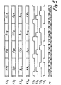
- the multiplex formation in the central-side multiplexer must be explained beforehand. This is done with the aid of FIG. 5.
- the multiplexer has only four inputs, namely the inputs KS 1 to KS 4 , ie the number m is assumed to be 4 and the exemplary system is dimensioned for four television programs.
- lines KS 1 to KS 4 show sections of 4 bits each of the bit-rate and bit-edge-synchronous broadband signals present at the inputs of the same name in the multiplexer Mux.
- KK denotes the channel identifier
- B denotes the bits carrying the composite signal or the television sound. Indices indicate the affiliation to the individual channels and, in the case of the bits designated with B, their order among themselves.
- the display of frame identifier bits has been omitted.
- the phase relationship of significant bits (frame identifier and channel identifier bits) of a broadband signal to that of any other broadband signal is arbitrary.
- the multiplexer Mux these four broadband signals are interleaved bit by bit without an overframe identifier being added.
- the multiplex signal obtained in this way and designated M thus has exactly four times the bit rate of the individual broadband signals.
- such a multiplexer is made up of a plurality of gate circuits which are phase-shifted from one another and are edge-synchronous with respect to the signals to be interleaved, and which are controlled. Since there are four broadband signals here, four clocks TS 1 to TS 4 are accordingly provided, their assignment to the broadband signals KS 1 to KS 4 being indicated by the indices.
- the individual bits in the multiplex signal M have the same name as those of the individual broadband signals. It can be seen in what order, controlled by the positive pulses of the clocks, the individual bits of the broadband signals are combined to form the multiplex signal.
- the four clocks TS 1 to TS 4 are obtained in a manner not shown from the wideband signals present at the inputs KS 1 to KS 4 , as a result of which the required bit edge synchronization can be easily produced.
- the four clocks must have the phase position shown in FIG. 5 indicate, a certain phase position with respect to significant bits of the broadband signals is not required.
- FIG. 3 shows one of the demultiplexers, here Demux 1 / . It contains a clock generator TG, shown separately here, which generates a reception clock TE synchronous to the multiplex signal M from this multiplex signal.
- a demultiplexer is also constructed from gate circuits controlled by clock cycles. Since only one of the broadband signals is to be obtained here, a gate circuit and a receive clock TE are sufficient.
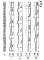
- FIG. 6 shows the multiplex signal M obtained in accordance with FIG. 5.
- the reception clock TE can initially have any phase position. Since there are four clocks with four different phase positions on the central side, four different phase positions are also interesting on the subscriber side. These are designated by TE in FIG. 6 under I to IV.
- KE denotes the bit sequences appearing for the line KE at the respective phase position of the reception clock TE at the output of the demultiplexer.
- the broadband signal obtained in this way is fed to the demodulator DEM via the line KE. Since none from the multiplexer Mux to the output of the demultiplexer Demux 1 If bits have been added or omitted, the transmission of the broadband signals as closed information blocks extends from the respective source Q 1 to Q k to the input of the demodulator DEM, which extracts the channel identifier KK and the CVBS signal B and the television sound by evaluating the frame identifier feeds the actual television FE.
- the channel identifier KK thus received and an identifier entered on an input keyboard ET of one of the television programs selected from the television programs P 1 to P m (see FIG. 1) are fed to a comparator V. None happens if there is a coincidence.
- the comparator V sends a control signal to the clock generator TG via the control line Stl, which is thereby stopped by the duration of one bit length of the multiplex signal M. It is thus achieved that the reception clock TE assumes the next of the possible phase positions with respect to the multiplex signal M and the corresponding broadband signal obtained reaches the demodulator DEM. This pause occurs until there is agreement between the received and the entered channel identifier.
- FIG. 4 it is described how the control line St1 provided according to FIG. 3 between the comparator V and the clock generator TG can be saved by using the line KE in addition for the transmission of the control signal from the comparator V to the clock generator TG. This is done by selecting an AC pulse with a frequency below the lowest frequency of the broadband signal or a DC pulse as the control signal and combining and separating both signals by the high-pass filters HP and HP 2 and the low-pass filters TP and TP 2 .
- the demodulator DEM, the comparator V and the input keyboard ET are in the actual television set FE or in its proximity, which is indicated by the common frame.
- the designation of this block with E 1 makes it clear that it corresponds to the television receiver E 1 shown in FIG.
- the system according to the invention is characterized by a simple clock supply. Only the few sources for the television programs have to be supplied with clocks which are synchronized with one another, which requires the clock line designated TL in FIG. 1. The clocks only need to be synchronized with one another, a specific phase relationship to one another is not required, because with the broadband signals present at the inputs of the multiplexers in the central stations, no specific phase relationship with one another is required.
- the system according to the invention also has the advantage that, because of the use of digital broadband signals, fiber optic cables can be used both between the sources and central stations and in the distribution network, as a result of which a substantial reduction in cable costs in the distribution network is achieved.
- fiber optic cables can be used both between the sources and central stations and in the distribution network, as a result of which a substantial reduction in cable costs in the distribution network is achieved.
- the usability of glass fibers has the advantage that cables designed for other services can also be used.
- a separate standard clock source can be omitted if an existing network intended for the supply of other digital telecommunications systems is also used to distribute a standard clock.
- an existing network intended for the supply of other digital telecommunications systems is also used to distribute a standard clock.
- Simple clock generators in the sources Q 1 to Q k result if the bit rates are selected as integer multiples of this standard clock. For example, a bitrate of 34.816 Mbit / s is achieved with a seventeen-fold increase. Whether you choose this or double (69.632 Mbit / s) or quadruple (139.264 Mbit / s) bit rate for the broadband signals depends on how much effort is required to reduce the redundancy and the associated bandwidth reduction of the image signal. This consideration also applies for which bit rate the many connecting lines, transmission-side multiplexers and subscriber-side demultiplexers can be produced economically.
- the broadband signals all have the same bit rate. This is advantageous if only services of the same type are to be transmitted.
- the broadband signals have different bit rates, the higher bit rates being integer multiples of the lowest bit rate.
- FIGS. 1 to 4 and the associated text also apply here analogously.
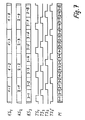
- This difference is explained on the basis of FIGS. 7 to 9, FIG. 7 relating to the formation of the multiplex signal M in the central multiplexer.
- FIG. 5 this is also accepted for the sake of simplicity of illustration men that the multiplexer has only the three inputs KS, to KS 3 , the inputs KS 1 and KS 2 for the low bit rate and the input KS 3 for the double bit rate.
- the multiplexing also takes place again by means of several clock-shifted clocks TS 1 , TS 2 , TS 3 , TS 3 ', the clocks TS 1 and TS 2 being assigned to the inputs KS 1 and KS 2 , respectively.
- the two clocks TS 3 and TS 3 t are assigned to the input KS 3 , their phase position relative to the broadband signal being selected such that each positive clock pulse samples a different bit of this broadband signal.
- the broadband signals must also be bit-edge-synchronous here; a specific phase relationship of their significant bits to each other is not required here either. Therefore, the channel identification bits have not been specifically designated here.
- the designation of the individual bits now only indicates which of the inputs KS 1 to KS 3 they are assigned to and the number of bits in the short section of the broadband signal in question, which is considered here.
- the selection of the desired broadband signal is carried out as in the first exemplary embodiment, i.e. as described with reference to Figures 3 and 4.
- integer multiples of the broadband signals of high bit rate enables a similarly simple construction of the multiplexers and demultiplexers as for systems with the same bit rate of all broadband signals.
- the multiplex signal M is obtained by bit-wise interleaving. Instead, however, word-by-word nesting is also possible.
- Word-by-word interleaving has the advantage over bit-wise that in the demodulator DEM (FIG. 3) the frame identifier is recognized faster, the channel identifier is extracted faster and the desired television program is switched through more quickly.
- bitwise nesting has the advantage that bit streams with a high bit rate can be handled more easily in the multiplexer and demultiplexer.
Priority Applications (1)
| Application Number | Priority Date | Filing Date | Title |
|---|---|---|---|
| AT86109797T ATE50109T1 (de) | 1985-08-20 | 1986-07-17 | Breitband-verteil-kommunikationssystem. |
Applications Claiming Priority (2)
| Application Number | Priority Date | Filing Date | Title |
|---|---|---|---|
| DE3529666 | 1985-08-20 | ||
| DE19853529666 DE3529666A1 (de) | 1985-08-20 | 1985-08-20 | Breitband-verteil-kommunikationssystem |
Publications (2)
| Publication Number | Publication Date |
|---|---|
| EP0212261A1 true EP0212261A1 (fr) | 1987-03-04 |
| EP0212261B1 EP0212261B1 (fr) | 1990-01-31 |
Family
ID=6278859
Family Applications (1)
| Application Number | Title | Priority Date | Filing Date |
|---|---|---|---|
| EP86109797A Expired - Lifetime EP0212261B1 (fr) | 1985-08-20 | 1986-07-17 | Système de distribution et de communication à large bande |
Country Status (3)
| Country | Link |
|---|---|
| EP (1) | EP0212261B1 (fr) |
| AT (1) | ATE50109T1 (fr) |
| DE (2) | DE3529666A1 (fr) |
Cited By (1)
| Publication number | Priority date | Publication date | Assignee | Title |
|---|---|---|---|---|
| WO1990012472A1 (fr) * | 1989-02-10 | 1990-10-18 | Salim Antoine Kassatly | Methode et appareil de telediffusion |
Families Citing this family (2)
| Publication number | Priority date | Publication date | Assignee | Title |
|---|---|---|---|---|
| US5691777A (en) | 1988-10-17 | 1997-11-25 | Kassatly; Lord Samuel Anthony | Method and apparatus for simultaneous compression of video, audio and data signals |
| US5767913A (en) | 1988-10-17 | 1998-06-16 | Kassatly; Lord Samuel Anthony | Mapping system for producing event identifying codes |
Citations (6)
| Publication number | Priority date | Publication date | Assignee | Title |
|---|---|---|---|---|
| GB2038147A (en) * | 1978-11-24 | 1980-07-16 | Hitachi Ltd | Buffer memory dispersion type video/audio distribution system |
| EP0058417A2 (fr) * | 1981-02-17 | 1982-08-25 | Sony Corporation | Méthode de transmission de données par multiplex à division de temps |
| DE3242580A1 (de) * | 1982-11-18 | 1984-09-27 | ANT Nachrichtentechnik GmbH, 7150 Backnang | Verfahren zur gewinnung von analogen tonrundfunksignalen aus einem seriellen multiplexbitstrom eines digitalen teilnehmeranschlusses |
| EP0120806A2 (fr) * | 1983-03-18 | 1984-10-03 | Heinrich-Hertz-Institut für Nachrichtentechnik Berlin GmbH | Circuit sélecteur de canal pour des canaux numériques à large bande à intercalage de bits |
| EP0144077A2 (fr) * | 1983-12-01 | 1985-06-12 | ANT Nachrichtentechnik GmbH | Réseau de transmission numérique à intégration de services |
| EP0144075A2 (fr) * | 1983-12-01 | 1985-06-12 | ANT Nachrichtentechnik GmbH | Réseau de transmission numérique à intégration de services |
-
1985
- 1985-08-20 DE DE19853529666 patent/DE3529666A1/de not_active Withdrawn
-
1986
- 1986-07-17 AT AT86109797T patent/ATE50109T1/de not_active IP Right Cessation
- 1986-07-17 EP EP86109797A patent/EP0212261B1/fr not_active Expired - Lifetime
- 1986-07-17 DE DE8686109797T patent/DE3668746D1/de not_active Expired - Fee Related
Patent Citations (6)
| Publication number | Priority date | Publication date | Assignee | Title |
|---|---|---|---|---|
| GB2038147A (en) * | 1978-11-24 | 1980-07-16 | Hitachi Ltd | Buffer memory dispersion type video/audio distribution system |
| EP0058417A2 (fr) * | 1981-02-17 | 1982-08-25 | Sony Corporation | Méthode de transmission de données par multiplex à division de temps |
| DE3242580A1 (de) * | 1982-11-18 | 1984-09-27 | ANT Nachrichtentechnik GmbH, 7150 Backnang | Verfahren zur gewinnung von analogen tonrundfunksignalen aus einem seriellen multiplexbitstrom eines digitalen teilnehmeranschlusses |
| EP0120806A2 (fr) * | 1983-03-18 | 1984-10-03 | Heinrich-Hertz-Institut für Nachrichtentechnik Berlin GmbH | Circuit sélecteur de canal pour des canaux numériques à large bande à intercalage de bits |
| EP0144077A2 (fr) * | 1983-12-01 | 1985-06-12 | ANT Nachrichtentechnik GmbH | Réseau de transmission numérique à intégration de services |
| EP0144075A2 (fr) * | 1983-12-01 | 1985-06-12 | ANT Nachrichtentechnik GmbH | Réseau de transmission numérique à intégration de services |
Cited By (2)
| Publication number | Priority date | Publication date | Assignee | Title |
|---|---|---|---|---|
| WO1990012472A1 (fr) * | 1989-02-10 | 1990-10-18 | Salim Antoine Kassatly | Methode et appareil de telediffusion |
| US4975771A (en) * | 1989-02-10 | 1990-12-04 | Kassatly Salim A | Method and apparatus for TV broadcasting |
Also Published As
| Publication number | Publication date |
|---|---|
| DE3668746D1 (de) | 1990-03-08 |
| ATE50109T1 (de) | 1990-02-15 |
| DE3529666A1 (de) | 1987-02-26 |
| EP0212261B1 (fr) | 1990-01-31 |
Similar Documents
| Publication | Publication Date | Title |
|---|---|---|
| EP0151454B1 (fr) | Branchement d'abonné dans un système intégré à large bande | |
| DE3614361C2 (fr) | ||
| DE4242800B4 (de) | System für eine integrierte Verteilung von geschalteten Sprach- und Fernsehsignalen auf einem Koaxialkabel und mit Videosignalübertragung ausgehend von Teilnehmerstellen | |
| EP0090236A2 (fr) | Système pour la transmission numérique de signaux d'images de télévision à redondance réduite | |
| DE3146468A1 (de) | Multiplexkonzept fuer ein digitales optisches teilnehmeranschlussnetz | |
| EP0706292B1 (fr) | Circuit pour commander la transmission d'information de services interactifs | |
| EP0212261B1 (fr) | Système de distribution et de communication à large bande | |
| DE3707243C2 (fr) | ||
| EP0226802B1 (fr) | Système de transmission d'informations de télévision | |
| DE3138473A1 (de) | Dienstintegriertes nachrichtenuebertragungs- und vermittlungsnetz fuer bild, ton und daten | |
| EP0144077A2 (fr) | Réseau de transmission numérique à intégration de services | |
| DE3129731A1 (de) | Digitales breitband-kommunikationssystem | |
| EP0645908B1 (fr) | Procédé de multiplexage par partage du temps | |
| EP0205863A1 (fr) | Système de distribution de communications à large bande | |
| EP0324954A2 (fr) | Procédé et dispositif pour la transmission en partage de signaux numérisés de télévision, de son et de données | |
| EP0144076A2 (fr) | Réseau de transmission numérique à intégration de services | |
| EP0144075A2 (fr) | Réseau de transmission numérique à intégration de services | |
| DE3503616C2 (fr) | ||
| DE19723760B4 (de) | Einrichtung und Verfahren zum Empfang von Daten | |
| EP0730800B1 (fr) | Procede et circuit permettant de diffuser des informations sur des programmes emis, de preference sur des reseaux automatiques de telecommunication a large bande | |
| DE102005026173B4 (de) | Verfahren und Zeitmultiplex-/Demultiplexeinheit zur Datenübertragung im Zeitmultiplex, insbesondere zur bandbreiten-optimierten Datenübertragung von IP Verkehr mit Broadcast- und Multicast-Anteilen in einem WDM-System | |
| EP0883263A2 (fr) | Dispositif pour la transmission de signaux numériques | |
| DE19847777A1 (de) | Einrichtung zur Datenübertragung | |
| DE3901868C1 (en) | Channel distributor for plesiochronous signals | |
| DE4136112A1 (de) | Verfahren zur aufbereitung von bildquellsignalen mit oder ohne tonsignalen sowie anwendung |
Legal Events
| Date | Code | Title | Description |
|---|---|---|---|
| PUAI | Public reference made under article 153(3) epc to a published international application that has entered the european phase |
Free format text: ORIGINAL CODE: 0009012 |
|
| AK | Designated contracting states |
Kind code of ref document: A1 Designated state(s): AT CH DE FR IT LI NL SE |
|
| 17P | Request for examination filed |
Effective date: 19870320 |
|
| 17Q | First examination report despatched |
Effective date: 19890426 |
|
| GRAA | (expected) grant |
Free format text: ORIGINAL CODE: 0009210 |
|
| AK | Designated contracting states |
Kind code of ref document: B1 Designated state(s): AT CH DE FR IT LI NL SE |
|
| REF | Corresponds to: |
Ref document number: 50109 Country of ref document: AT Date of ref document: 19900215 Kind code of ref document: T |
|
| ITF | It: translation for a ep patent filed |
Owner name: BARZANO' E ZANARDO MILANO S.P.A. |
|
| ET | Fr: translation filed | ||
| REF | Corresponds to: |
Ref document number: 3668746 Country of ref document: DE Date of ref document: 19900308 |
|
| PLBE | No opposition filed within time limit |
Free format text: ORIGINAL CODE: 0009261 |
|
| STAA | Information on the status of an ep patent application or granted ep patent |
Free format text: STATUS: NO OPPOSITION FILED WITHIN TIME LIMIT |
|
| 26N | No opposition filed | ||
| ITTA | It: last paid annual fee | ||
| PGFP | Annual fee paid to national office [announced via postgrant information from national office to epo] |
Ref country code: DE Payment date: 19930910 Year of fee payment: 8 |
|
| PGFP | Annual fee paid to national office [announced via postgrant information from national office to epo] |
Ref country code: FR Payment date: 19940715 Year of fee payment: 9 |
|
| PGFP | Annual fee paid to national office [announced via postgrant information from national office to epo] |
Ref country code: SE Payment date: 19940727 Year of fee payment: 9 Ref country code: AT Payment date: 19940727 Year of fee payment: 9 |
|
| PGFP | Annual fee paid to national office [announced via postgrant information from national office to epo] |
Ref country code: NL Payment date: 19940731 Year of fee payment: 9 |
|
| PGFP | Annual fee paid to national office [announced via postgrant information from national office to epo] |
Ref country code: CH Payment date: 19940819 Year of fee payment: 9 |
|
| EAL | Se: european patent in force in sweden |
Ref document number: 86109797.0 |
|
| PG25 | Lapsed in a contracting state [announced via postgrant information from national office to epo] |
Ref country code: DE Effective date: 19950401 |
|
| PG25 | Lapsed in a contracting state [announced via postgrant information from national office to epo] |
Ref country code: AT Effective date: 19950717 |
|
| PG25 | Lapsed in a contracting state [announced via postgrant information from national office to epo] |
Ref country code: SE Effective date: 19950718 |
|
| PG25 | Lapsed in a contracting state [announced via postgrant information from national office to epo] |
Ref country code: LI Effective date: 19950731 Ref country code: CH Effective date: 19950731 |
|
| PG25 | Lapsed in a contracting state [announced via postgrant information from national office to epo] |
Ref country code: NL Effective date: 19960201 |
|
| REG | Reference to a national code |
Ref country code: CH Ref legal event code: PL |
|
| NLV4 | Nl: lapsed or anulled due to non-payment of the annual fee |
Effective date: 19960201 |
|
| EUG | Se: european patent has lapsed |
Ref document number: 86109797.0 |
|
| PG25 | Lapsed in a contracting state [announced via postgrant information from national office to epo] |
Ref country code: FR Effective date: 19960430 |
|
| REG | Reference to a national code |
Ref country code: FR Ref legal event code: ST |
|
| REG | Reference to a national code |
Ref country code: FR Ref legal event code: ST |
|
| REG | Reference to a national code |
Ref country code: FR Ref legal event code: ST |
|
| PG25 | Lapsed in a contracting state [announced via postgrant information from national office to epo] |
Ref country code: IT Free format text: LAPSE BECAUSE OF NON-PAYMENT OF DUE FEES;WARNING: LAPSES OF ITALIAN PATENTS WITH EFFECTIVE DATE BEFORE 2007 MAY HAVE OCCURRED AT ANY TIME BEFORE 2007. THE CORRECT EFFECTIVE DATE MAY BE DIFFERENT FROM THE ONE RECORDED. Effective date: 20050717 |