EP0211740A1 - Mast-Nabeneinheit und Drehflügerrotorkopf mit einer solchen Einheit - Google Patents
Mast-Nabeneinheit und Drehflügerrotorkopf mit einer solchen Einheit Download PDFInfo
- Publication number
- EP0211740A1 EP0211740A1 EP86401622A EP86401622A EP0211740A1 EP 0211740 A1 EP0211740 A1 EP 0211740A1 EP 86401622 A EP86401622 A EP 86401622A EP 86401622 A EP86401622 A EP 86401622A EP 0211740 A1 EP0211740 A1 EP 0211740A1
- Authority
- EP
- European Patent Office
- Prior art keywords
- mast
- hub
- hub body
- rotor
- openings
- Prior art date
- Legal status (The legal status is an assumption and is not a legal conclusion. Google has not performed a legal analysis and makes no representation as to the accuracy of the status listed.)
- Granted
Links
Images


Classifications
-
- B—PERFORMING OPERATIONS; TRANSPORTING
- B64—AIRCRAFT; AVIATION; COSMONAUTICS
- B64C—AEROPLANES; HELICOPTERS
- B64C27/00—Rotorcraft; Rotors peculiar thereto
- B64C27/32—Rotors
Definitions
- the present invention relates to rotorcraft rotors, and more specifically relates to an integrated mast-hub, as well as a rotor head comprising this integrated mast-hub and intended in particular for equipping helicopters.
- the helicopter rotors described in these documents each comprise a central body of rigid hub, to which the foot of each rotor blade is coupled by means of a laminated spherical abutment and a drag damper, or a elastic stretcher against drag with incorporated damping.
- the laminated spherical stop which constitutes an articulation allowing the movements of the corresponding blade around its three axes of beat, drag and control of the incidence, comprises a laminated central part, formed of an alternating stack of spherical caps of a rigid material and a visco-elastic material and working in compression and shear between an external reinforcement secured to the hub and an internal reinforcement fixed to a member for connecting to the blade.
- the drag damper which can be hydraulic but which, preferably, consists of an alternating stack of rigid plates and plates of a visco-elastic material, or of coaxial tubes between which a cylindrical sleeve is incorporated. an elastic material, at its ends coupled by ball joints at the foot of the corresponding blade and at one point of the hub, so that for the angular movements of the drag blade, it provides an energetic elastic return on the neutral axis by introducing simultaneously a certain damping of these movements.
- the central body of the hub has the form of a plate or a flat ring, of polygonal convex or substantially circular periphery, extending substantially radially with respect to the axis of rotation. of the rotor, which coincides with the axis of the mast-rotor supporting the hub, and this plate is crossed, in the direction of the axis of the rotor, by as many openings or cells as the rotor comprises blades.
- a laminated spherical abutment is mounted to rest by its external armature against the external edge of each opening, while its internal armature is fixed to the internal ends of the branches of a forked part integral with the foot of the corresponding blade, and the point of the periphery of the hub, to which the corresponding drag damper is coupled by a ball joint, is located between the corresponding laminated spherical stop and that of the immediately preceding or following blade of the corresponding blade, in the direction of rotation of the rotor.
- a lever for controlling the incidence of the corresponding blade is fixed to the forked part, on the side opposite to the corresponding drag damper, and, finally, in the case of a main rotor, the lower branch of the forked part carries, under its internal end, a stop limiting the beat of the corresponding blade downwards, by the cooperation with a reciprocal ring mounted sliding radially around the mast-rotor, below the hub, so that the stop come to rest against the reciprocal ring at low rotational speeds and when the rotor stops.
- the forked part can be constituted by an extension of the foot of the corresponding blade, or also by a radial yoke at the internal end of an attached member for connection to the foot of the corresponding blade, the two branches of this end yoke internal or of this extension being fixed to the internal reinforcement of the corresponding laminated spherical stop by two bolts.
- this member also has ment., at its outer end, another yoke by which it is secured to the foot of the corresponding blade by two axes substantially perpendicular to the plane of the rotor, one of which is removable to allow the blade to be folded back into the plane of the rotor by pivoting around the other axis.
- this attached connecting member be shaped as a sleeve, a cylindrical part of which accommodates this device, and which also serves to fix the lever for controlling the incidence of the corresponding blade, the corresponding drag damper, and the bottom stop cooperating with the reciprocal ring.
- the central body of the hub and the mast can be integrated, and it has been proposed that the rigid central body of the hub constitutes, together with the rotor mast, a one-piece metallic piece, for example of steel or titanium and coming from forging or forging.
- the latter can be made of composite materials, by stacking or draping plies of fabrics of synthetic or mineral fibers with high mechanical strength which are pre-impregnated and agglomerated with a synthetic resin which is subsequently polymerized and hardened.
- a belt of composite structure is advantageously wound around the hub plate.
- the rotors described in the first certificate of addition no. 2,456,034 to the French patent mentioned above are essentially distinguished from those which are the subject of this main patent by the fact that their hub body comprises a central barrel, extending the rotor mast, and carrying an upper plate and a plate lower, the external reinforcement of each laminated spherical stop being embedded between and fixed directly to the edges of the two plates, in the manner of a rigid spacer, and the foot of the corresponding blade being joined to the internal reinforcement of the spherical stop laminated by a radial yoke and hollowed out for the free passage of the spherical stop.
- 2,529,860 which comprise two plates of composite materials fixed to a metal spacer, which separates them, and on the upper part of the metal rotor mast by bolts, in a basic architecture identical to that of the rotors described in French patent application n ° 81 22 027 and differing essentially from the rotors of the above mentioned certificate of addition by the fact that the foot of each blade has a loop which directly surrounds the corresponding laminated spherical stop and is fixed to the internal reinforcement of the latter .
- the invention relates to an integrated mast-hub having both a simplified and lighter structure, improved safety and reliability, and which can be manufactured in metal or composite material in a simpler, more economical and more reliable way.
- the subject of the invention is therefore an integrated mast-hub, the mass of which is lower and the service life of which is increased and the maintenance simplified, which makes it possible to lower the direct costs in operation.
- the invention further relates to an integrated mast-hub, the structure of which is advantageously adapted to an embodiment made of composite materials, so that it has a good "fail safe” character.
- the integrated hub according to the invention of the lype comprising a tubular spoke lormant a mat, one end of which is shaped at the bottom by which the mast-hub is intended, on the one hand, to be connected to the upper part of the helicopter's gearbox, to transfer to the fuselage the forces and moments coming from the rotor, and, on the other hand, to be driven in rotation around the axis of the mast part, which is integral, on the side opposite the foot, with a part forming a body of hub coaxial with the mast part and intended to be connected to rotor blades, is characterized in that the part forming the hub body is also a tubular part which extends the mast part, and in that pairs of openings , equal in number to the number of rotor blades, are formed in the part forming the hub body and are regularly distributed in circumferential direction around the periphery of this part forming the hub body, the two openings of each pair being axially spaced apart on the other, and a reinforcement belt, preferably made
- the ends in the circumferential direction of the openings on the one hand nearest and on the other hand furthest from the mast portion are located substantially and respectively in a first and in a second transverse plane perpendicular to the axis of the mast-hub, and the reinforcement belt is fixed against the annular band delimited on the internal or external face of the part forming the hub body between the first and the second transverse plane.
- the two openings of each pair have substantially a bean shape and have their concavity turned towards one another.
- the mast part and the hub body part are constituted by a single tubular part with symmetry of revolution, and the two openings of each pair of openings are symmetrical to each other with respect to a median plane of the reinforcing belt which is perpendicular to the axis of the mast-hub.
- the reinforcement belt has a lateral surface outer substantially in the form of a circular ring and an inner lateral surface substantially in the form of a ring of polygonal section.
- At least the mast part has a generally frustoconical external shape diverging from the base of this part towards the hub body part, so that the diameter of the base of the mast-hub can be adapted to a drive device. and rotational mounting comprising at least one bearing whose size is relatively large without being prohibitive.
- the general arrangement of such an integrated mast-hub is particularly advantageous for an embodiment of composite material with high mechanical strength fibers.
- nique agglomerated by a hardened synthetic resin, and, in this case, the belt is made of composite and advantageously made in one piece with the hub part, which has a generally external shape that is substantially convex.
- the parts forming the mast and the hub body are made of metal, the part forming the hub body having a generally external substantially cylindrical or frustoconical shape diverging towards its free end opposite the part forming the mast, in order to allow the setting in place the belt, composite or metal, inside or around the hub mast.
- a metallic embodiment has less advantages in terms of weight, cost and resistance to the notch effect ("fail-safe" character) than a composite embodiment, which, in a preferred embodiment , is such that the part forming the hub body has substantially the shape of a barrel of maximum diameter at the level of the belt.
- a mast-hub the shape of which is advantageous for aerodynamic drag considerations, lends itself easily to the manufacture of carbon fiber or Kevlar composite, or by winding rovings of these materials pre-impregnated with an epoxy resin which is then polymerized and hardened, either by draping fiber fabrics of these materials prepreg of an epoxy resin, then pressure molding and hot polymerization of the resin, the openings being subsequently machined in the mast-hub.
- a rigid reciprocal ring is mounted laterally sliding in a circular U-shaped housing opening radially towards the exterior and maintained by a support coaxially to the mast-hub and inside the latter, at an axial level located between the mast portion and the openings closest to this mast portion.
- this support comprises a frustoconical portion, internal to the part forming the hub body and which carries the circular housing at its small base, while its large base is extended by a flared and folded portion, outside of the part forming the hub body, over the free edge of this part to which the support is fixed by screws.
- the latter has a substantially frustoconical tubular bearing bearing against the internal face of the mast portion and a tubular centering veil also substantially frustoconical which is integral with the bearing surface and which supports the circular housing.
- coupling attachments in number equal to the number of pairs of openings, are preferably each fixed by a base against the external face of the part forming the hub body or of the belt, at an axial level situated substantially between the two openings of the pairs of openings, and the base extends circumferentially around the periphery of the hub body part or of the belt between two adjacent pairs of openings.
- the circumferential extension of an attachment base between two adjacent pairs of openings allows a better distribution of the stresses in the mast-hub, without localized concentration of stresses, as would be obtained if the base of each attachment had a small bearing surface on the part forming the hub body.
- the foot of the mast-forming part is preferably bolted to a fitting for connection to this device.
- the subject of the invention is also a rotor head, for rotorcraft rotor, of the type comprising an integrated mast-hub intended to be driven in rotation about the axis of the rotor by one of its parts forming a mast, and having a part forming a hub body and to which rotor blades are each connected by a forked attachment part with two branches and by means of, on the one hand, retaining and articulation members, comprising preferably at least one laminated stop, of which an external reinforcement is fixed to the part forming the hub body and of which an internal reinforcement is fixed to the internal ends of the two branches, and, on the other hand, of an elastic return member and d drag damping, the ends of which are articulated by ball joints, one on the forked attachment part of the corresponding blade and the other at a point in the part forming the hub body, and this rotor head is characterized by that the integrated mast-hub conforms to i nvention and as presented above, and in that the retaining bodies and articu -
- the opening of the free end of the hub body part must be sufficient to allow the introduction of the retaining and articulation members inside the hub body part, and the internal cross section of this part forming the hub body, at the level of the reinforcement belt, must be sufficient for the arrangement of the retaining and articulation members supported by their external armature against the belt or against the hub body and between the two openings of the pairs openings, and for fixing the internal ends of the two branches of the forked attachment parts of the blades on the internal reinforcements of the retaining and articulation members, hence the advantage of the barrel shape of the, forming part body hub.
- the diameter of the mast-hub is always relatively large, and the stresses due to the torque and the moment (induced respectively by the forces of drag and flapping on the blades) are weak.
- This arrangement of the retaining and articulation members in the portion forming the hub body considerably reduces, in the hub mast, the bending and shear stresses due to alternating cutting forces, at the level of these members, especially if the latter are constituted, for each blade, by a laminated spherical stop fixed on the part forming the hub body so that its center of rotation is practically in the thickness of the part forming the hub body or of the belt, between the two corresponding openings .
- the centrifugal forces from the blades are taken care of and balanced - between said blades by the reinforcement belt, working in traction, and thus these forces practically do not stress the mast-hub.
- the mast-hub undergoes only slight torsional stresses due to the engine torque, which is transmitted to the foot of the mast-forming part to drive the mast-hub in rotation.
- the shearing forces of flapping pass directly from the retaining and articulation members at the foot of the mast-hub, following a path practically in a straight line, and with moderate tension / compression constraints.
- the arrangement of the rotor head according to the invention makes it possible to bring the retaining and articulation members as close as possible to the axis of the rotor, since the central volume of the part forming the hub body is not occupied by of the material.
- This technical measure leads not only to a reduced bulk of the mast-hub, hence a mass and aerodynamic drag also reduced, but also to a lower level of vibratory excitation, because the eccentricity of beat is lower, by comparison with the achievements of the prior art presented and above.
- this external reinforcement is advantageously shaped outwardly as a stirrup which covers the reinforcing belt and the portion of the portion forming the hub body which is delimited between the two corresponding openings, and a cover, applied against the external face of the belt or of this portion of the hub body part is screwed onto the caliper and holds the corresponding retaining and articulation members in place inside the hub body part.
- a rigid heel is advantageously secured to the lower branch of the forked attachment part of the corresponding blade by two bolts which secure the internal ends of the two arms of this forked attachment part to the internal frame of the corresponding retaining and articulation members.
- the elastic return member and drag damping, provided for each blade of the rotor is advantageously mounted outside the part forming the hub body, between one of the coupling fasteners fixed against the external face of the belt or of this part forming the hub body and a coupling fastener carried by the forked fastening part of the corresponding blade.
- the rotor head according to the invention also comprises a lever for controlling the incidence of the blade, and this lever is fixed on the corresponding forked attachment part, on the side opposite to the reminder, and outside the hub body part.
- the forked attachment part of each blade is a substantially radial attachment sleeve, shaped, at its internal end, in a yoke, the two branches of which are fixed to the internal reinforcement of the corresponding retaining and articulation members, and also shaped, at its external end, as a fixing bracket at the foot of the corresponding blade by two axes substantially parallel to the axis of rotation of the rotor and of which one is removable, to allow folding of the blade by pivoting around the other axis.
- the rotor head according to the invention consists of a small number of parts all having relatively simple shapes and adapted to the forces to be subjected, which makes it possible to reduce the mass and the costs. manufacturing and maintenance of this rotor head, while improving its stability and reducing vibrations, which is a factor of safety and reliability.
- a rotor head according to the invention is limited due to the housing of the retaining and articulation members and of the low stop device in the integrated mast-hub, the aerodynamic drag is reduced, and all of these advantageous results contribute to increasing the performance of a helicopter equipped with such a rotor head, both at the level of its main or lift rotors or at the level of its rear rotor or anti-torque.
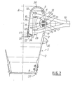
- the main rotor head comprises an integrated mast-hub 1, essentially consisting of a one-piece tubular body, with symmetry of revolution, the lower part of which forms a tubular mast 2, while its upper part forms a tubular hub body 3.
- the mast forming part 2 has a generally frustoconical external general shape, and diverges from its lower end, shaped as a thickened foot 4, towards its upper end, also thickened and by which this mast part 1 is connected to the hub body part 3 and is extended directly by this part i, which has a generally convex exterior shape, in a barrel open at its free upper end 5.
- the edge of the free upper end 5 of the mast-hub 1 delimits a circular opening whose diameter corresponds substantially to the internal diameter of the connection portion of the parts forming mast 2 and hub body 3.
- This one-piece tubular body is produced by winding rovings of carbon and / or Kevlar (registered trademark) pre-impregnated with an epoxy resin and then by polymerization of the resin which is hardened, or by draping plies of fabrics of carbon fibers and / or Kevlar pre-impregnated with epoxy resin, and hot and pressure molding to polymerize and harden the resin.
- a belt 6 of composite structure is disposed inside the hub body part 3.
- This belt 6 consisting of: unidirectional rovings of carbon or Kevlar, has an internal lateral face, delimited by an annular surface of cross section essentially polygonal, and an external lateral face, delimited by an annular surface of circular section, slightly convex, of convex shape corresponding to the concavity of the internal face of the barrel part forming hub body 3, and by which the belt 6 is integral with this part forming the hub body 3.
- the belt 6 is symmetrical with respect to a median plane M, perpendicular to its axis, and it is secured to the part forming the hub body 3 so that its median plane M is located in the plane perpendicular to the axis A of the mast-hub 1 and passing through the section of larger internal diameter of the barrel part forming the hub body 3.
- the belt 6 is d onc attached to the internal face of the part forming the hub body 3, on a band of annular surface delimited on this internal face between two transverse planes P 1 and P 2 , perpendicular to the axis A and located at equal distance apart and other from the midplane M of the belt (the trace of these planes M, P 1 and P being indicated in broken lines in FIG. 3).
- the belt 6, on which the tubular body of the mast-hub 1 is molded, is produced in the form of a wound ring whose internal lateral face (FIGS. 4 and 8) has the shape of a pseudo-regular polygon with short sides. equal 8 alternated with long sides equal 9 and equal in number to the number of rotor blades, the vertices of the polygon being substantially rounded, and the external lateral face of the wound ring forming the belt 6 is wound circularly to the internal diameter of the hub body.
- the recess 7 has a substantially square plan shape, delimited by four long sides 9 connected by four short sides 8 (one of which is visible in Figure 4), these latter corresponding, on the internal lateral face of the belt 6, to facets against which are fixed laminated spherical stops as explained more precisely below.
- This particular shape of the belt 6 makes it possible to give it excellent rigidity.
- pairs of bean-shaped openings in a number equal to the number of rotor blades, are machined in the part forming the hub body 3.
- the four pairs of openings are regularly distributed in circumferential direction around the periphery of the barrel part 3, and each pair of openings is pierced opposite one of the short sides 8 of the internal polygonal recess 7 belt 6.
- the two openings 10 and 11 of each pair are axially spaced on either side of the belt 6, one being a lower opening 10 pierced in the region of the hub body part 3 which extends between the belt 6 and the mast part 2, and the other opening being an upper opening 11 pierced in the region of the hub body part 3 which extends between the belt 6 and the upper edge 5 of this part in barrel 3.
- the openings 10 and II are bean-shaped and have their concavity turned towards one another, being symmetrical with each other with respect to the median plane M of the belt 6, as is clearly shown in FIG. 3.
- the two openings 10 and 11 of the same pair define between them, on the barrel part forming the hub body 3, a portion extending in circumferential direction and in the form of a bridge 12.
- Each of the four blades of the rotor is connected to the part forming the hub body 3 by a laminated spherical stop, allowing the articulation of the blade on the hub 3 around its three axes of beat, drag and change of pitch, which intersect at the point of swiveling determined by the center of rotation of the corresponding laminated spherical stop.
- This member is now a well-known component, essentially comprising a laminated central part, consisting of a stack of layers in the form of spherical and alternately rigid caps, for example metallic, and made of an elastic material, such as synthetic rubber, by example in silicone elastomer.
- This laminated central part being vulcanized between two rigid reinforcements, for example metallic.
- each spherical laminated stop 13 is applied against a small side 8 of the recess 7 of the composite belt 6, in look of a bridge 12 between the two corresponding openings 10 and 11, and the stop 13 is fixed against the belt 6 by sun external radial armature 14, shaped, in its external part, in a small stirrup open towards the outside in order to partially overlap the upper and lower faces of the belt 6, which ensures by simple pressing the transfer of forces and moments on the belt 6.
- the external frame 14 is fixed to the concave external face of the laminated central part 15 of this stop 13, while this laminated central part 15 is fixed, by its convex inner face of the concave outer radial part of the internal frame 16.
- the spherical stop 13 is arranged inside the barrel part forming the hub body 3, so that its center of rotation is located in the plane median M of the belt 6 and in the thickness of the corresponding bridge 12, and the stop 13 is retained in position by means of a bolt 17 introduced from the outside of the hub body 3 in a socket 18 engaged in aligned holes s and drilled in the bridge. 12, the belt 6 and the external frame 14; into which the threaded end of the bolt rod 17 is screwed.
- each blade is partly shaped like a forked attachment 19 with two superimposed branches, the lower branch 20 of which passes through the corresponding lower opening 10, and the upper branch 21 passes through of the corresponding upper opening 11, the internal radial ends of the two branches 20 and 21 being fixed against the internal frame 16 of the spherical stop 13 by two bolts 22, which each pass through aligned holes drilled in the internal frame 16 and in these internal ends of the branches 20 and 21, the heads of the bolts 22 being in abutment against the upper face of the upper branch 21, and the threaded ends of the rods of the bolts 22 being screwed into a rigid heel 23 thus fixed against the lower face of the internal end of the lower branch 20.
- the internal frame 16 connecting the forked foot 19 of the blade to the spherical stop 13 also functions spacer maintaining the two arms 20 and 21 apart with a constant spacing.
- the heel 23 cooperates with a reciprocal ring 24, made of composite, with carbon fibers agglomerated in a hardened resin, and surrounded by a steel strip.
- This reciprocal ring 24 is mounted laterally or radially sliding in a U-shaped housing open towards the outside and formed by the association of a lower annular plate 25 screwed by a ring of screws 26 on an upper annular member 27 of section substantially in T-shape, itself screwed by several screws such as 28 on the constricted lower end of a frustoconical support 29, coaxial with the mast-hub 1, engaged in the latter by the opening of its upper edge 5, and of which the upper part 30 is flared and rounded towards the outside, and folded over the upper edge 5 of the part forming the hub body 3, to which this upper part 30 is fixed, for example by screws (not shown).
- the frusto-conical support 29 extends axially inside the mast-hub 1 over a distance sufficient for the U-shaped housing 25-27 and the reciprocal ring 24 to be slightly below the level of the lower openings 10, so that the heels 23 of the blades come to bear against the reciprocal ring 24 as soon as the blades are no longer sufficiently stressed by the centrifugal force and pivot down around the centers of rotation of the spherical stops 13 by a predetermined angle.
- the bottom stop device internal to the hub 3 and constituted by the reciprocal ring 24, the housing. 25-27 and the support 29, is dimensioned to absorb the static moment of the blades, when the rotor stops.
- each drag blade and the elastic return of the latter on its neutral axis are ensured by a member external to the mast-hub 1 and disposed laterally between the part forming the hub body 3 and the blade root 19.
- This organ called drag damper, against plug of elastic return in drag with incorporated damping or even frequency adapter, can be a hydraulic member or a visco-elastic member constituted by an alternating stack of rigid plates and plates of a visco-elastic material or coaxial tubes between which is incorporated a cylindrical sleeve of visco-elastic material.
- each blade also carries, on the side opposite the drag damper, a lever 34 for controlling the incidence of the blade, which is fixed to the foot 19 by two bolts 35.
- a clip 36 is fixed projecting outwards on the connection zone of the parts forming the mast 2 and hub body 3.
- a fitting 37 is bolted around the foot 4 of the mast-hub 1, in order to r-connect the latter to a device for rotating and embedding on the main gearbox, this device comprising at least one bearing. .
- the alternating cutting forces at the level of the spherical stops 13 induce in the hub mast 1 relatively low bending and shearing stresses, and in particular the vertical flapping forces transferred to the spherical stops 13 pass from the latter to the belt 6 and from the latter to the mast-hub 1 directly to the fitting 37 of its foot 4, with moderate tension / compression constraints.
- the mounting of the rotor is simple: after the hub mast 1 has been fitted on the main gearbox, the spherical stops 13 are successively introduced into the part forming the hub body 3 through the opening of the upper edge 5 of sufficient diameter. the latter, and fixed in position against the belt 6. Then, one by one, the forked blades 19 are presented, and the lower and upper branches 20 and .21 are engaged for each in the corresponding openings 10 and 11. The internal ends of the branches 20 and 21 are bolted then onto the internal frame 16 of the corresponding spherical stop 13, using the two bolts 22 which are screwed into the corresponding heel 23.
- the frustoconical support 29 is then presented from above on the lower end of which the U-shaped housing 25-27 and the reciprocal ring 24 have been previously mounted, and this support 29 is axially introduced into the mast 1 until that its curved part 30 comes to bear against the upper edge 5 of the mast mast 1, to which the curved part 30 is fixed by a ring of screws. Then the drag dampers are coupled to the mast-hub 1 and the levers for controlling the incidence of the blades to the corresponding control rods.
- Disassembly operations are carried out in reverse order.
- This arrangement of the rotor head makes it possible to bring the spherical stops 13, as well as the low stop device with reciprocal ring 24 and heels 23, closer to the axis A of the rotor, without hampering the movements of the blades relative in May hub I around the centers of rotation of the spherical stops 13, thanks to the passage and the deflections of the lower and upper branches 20 and 21 respectively in the bean-shaped openings 10 and 11 made in the mast-hub 1.
- This arrangement leads therefore with a reduced bulk, and with a less weight as well as with a less aerodynamic drag, and with a low level of vibratory excitation, owing to the fact that the eccentricity of beat is low.
- the second exemplary embodiment differs from that which has just been described by two main differences: one relates to the connecting member of each blade to the internal frame of the corresponding spherical stop, and the other the connection of the external frame of this spherical stop to the mast-hub 1.
- this rotor head is intended for a rotor with blades foldable by pivoting substantially in the plane of the rotor.
- the foot 38 of each blade shown in broken lines in FIG.
- the external end part of the sleeve 39 is also shaped as a yoke, and the blade root 38 is engaged between the lower branch 42 and the upper branch 43 of this outer yoke, being retained between them by two axes arranged side by side and perpendicular to the plane of the rotor, and which pass through these two branches 42 and 43 and the blade root 38, one axes being removable to allow the pivot away from the blade around the other axis.
- the sleeve 39 which, on one side, carries a fastener coupling at the outer end of the drag damper, and on the other side, carries the pitch control lever of the corresponding blade.
- the external frame 14 'of the spherical stop 13' is shaped, in its external part, as a stirrup 44 which covers the composite belt 6 and the bridge 12 of the part forming the hub body 3, between the two openings 10 and 11.
- a cover 45 is applied from the outside against the bridge 12 and against the external ends of the stirrup 44 to which the cover 45 is fixed by two lines of screws 46.
- This mounting has the advantage, compared to the use of a bolt 17 crossing the bridge 12 and the belt 6 and screwing into the internal frame 14, as shown in Figure 2, to allow the passage of all the forces and moments of the spherical stop 13 'to the mast-hub 1 by direct supports, without weakening the structure of the mast-hub 1 and that of the belt 6 by holes drilled in working parts.
- the third example is similar to the second example which has just been described in that, on the one hand, the foot 38 of each blade is connected to the internal frame 16 of the stop spherical 13 ′ corresponding by a sleeve 39 ′, the two end parts of which are shaped like yokes, so that the blade can pivot around one of the two attachment axes of the blade root 38 to the two branches 42 ′ and 43 'of the outer yoke, after removal of the other axis which is removable, and so that the internal frame 16 is mounted as a spacer between the inner ends of the two branches 40' and 41 'of the inner yoke.
- the external frame 14 'of the spherical stop 13' has its external part shaped as a stirrup 44 covering the belt 6 and the bridge 12 'and fixed by screws 46 to the cover 45.
- the bridge 12 ′ delimited between the openings 10 ′ and Il ′, has rectilinear upper and lower edges (see FIG. 7), which facilitates the realization openings 10 'and 11' of the stirrup 44 and t of the cover 45, as well as their positioning.
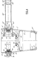
- the mast-hub 1 ' although frustoconical in its part forming the mast 2' and convex in its part forming the body of the hub 3 ', does not have a barrel shape in this part 3'.
- the hub mast l ' also composite, is produced by draping and of constant thickness, then it is machined at its ends to present a foot 4' and an upper end 5 'which are tapered, the foot 4' being pinched between two bolted fittings 37 'and 47 for connection to the device for rotating the mast-hub 1'.
- the reciprocal ring 24 is slidably mounted in a U-shaped housing open towards the outside and formed by bolting of an upper annular member 48, of L-shaped cross section, on a lower annular member 49, of section transverse T, itself nested and retained by screws (not shown) in the cylindrical upper part 51 of a support 50, composite or metal.
- This has a frustoconical veil 52 diverging downward and which is extended by a frustoconical centering surface 53, converging downward and by which the support 50 is in abutment against the internal face of the mast forming part 2 '.
- the reciprocal ring 24 cooperates with a heel 23 'fixed under the underside of the inner end of the lower branch 40' of the sleeve 39 'by the two bolts 22 for fixing the two branches 40' and 41 'to the frame internal 16 of the spherical stop 13.
- FIG. 6 there is shown a shock absorber attachment 31, the curved base 32, which extends between two adjacent pairs of openings 10 'and 11', is bolted against the external face of the body part hub 3 'by two lines of bolts 54, which simultaneously fix to the internal face of this part 3' a U-shaped sheet 55 with edges folded outwards, and intended to distribute the bearing forces of the bolts 54.
- L base 32 carries two attachment tabs 56 which are parallel to each other and between which is fixed the ball joint 57 of the end internal of the drag damper 58 (shown in FIG. 8), and which is coupled by another ball joint, at its external end, to the sleeve 39 '.
- the latter finally carries, on the side opposite the damper 58, the lever 34 'for controlling the pitch of the corresponding blade.
- the integrated mast-hub supports a reinforcement belt which is internal to the part forming the hub body.
- the reinforcement belt it is entirely possible to mount the reinforcement belt around this part forming the hub body.
- the couplings of the elastic return and drag damping members of the blades can be supported by the belt, while the external radial reinforcement of each laminated spherical stop is directly applied against the internal face of the hub body part.
Applications Claiming Priority (2)
| Application Number | Priority Date | Filing Date | Title |
|---|---|---|---|
| FR8511158A FR2584995B1 (fr) | 1985-07-22 | 1985-07-22 | Mat-moyeu integre et tete de rotor de giravion le comportant |
| FR8511158 | 1985-07-22 |
Publications (2)
| Publication Number | Publication Date |
|---|---|
| EP0211740A1 true EP0211740A1 (de) | 1987-02-25 |
| EP0211740B1 EP0211740B1 (de) | 1989-09-13 |
Family
ID=9321508
Family Applications (1)
| Application Number | Title | Priority Date | Filing Date |
|---|---|---|---|
| EP86401622A Expired EP0211740B1 (de) | 1985-07-22 | 1986-07-21 | Mast-Nabeneinheit und Drehflügerrotorkopf mit einer solchen Einheit |
Country Status (7)
| Country | Link |
|---|---|
| US (1) | US4749339A (de) |
| EP (1) | EP0211740B1 (de) |
| JP (1) | JPS6220797A (de) |
| CA (1) | CA1332053C (de) |
| DE (1) | DE3665555D1 (de) |
| FR (1) | FR2584995B1 (de) |
| IN (1) | IN167852B (de) |
Families Citing this family (7)
| Publication number | Priority date | Publication date | Assignee | Title |
|---|---|---|---|---|
| FR2630703B1 (fr) * | 1988-04-29 | 1990-08-24 | Aerospatiale | Tete de rotor de giravion a tirants interpales de rappel elastique avec amortissement incorpore |
| US4886419A (en) * | 1988-09-30 | 1989-12-12 | The Boeing Company | Elastomeric bearing for helicopter rotor having lead-lag damping |
| FR2653405B1 (fr) | 1989-10-20 | 1992-02-07 | Aerospatiale | Dispositif visco-elastique rotatif de rappel elastique et d'amortissement en trainee pour pale de rotor de giravion, et tete de rotor le comportant. |
| FR2671049B1 (fr) * | 1990-12-27 | 1993-12-24 | Aerospatiale | Corps de moyeu de rotor de giravion. |
| FR2685676B1 (fr) * | 1991-12-27 | 1994-04-01 | Aerospatiale Ste Nationale Indle | Tete de rotor articule pour giravion. |
| FR3046778B1 (fr) * | 2016-01-20 | 2018-01-12 | Airbus Helicopters | Dispositif de butee inferieur d'un rotor pour giravion, rotor de giravion et giravion |
| CN109835479B (zh) * | 2019-03-27 | 2021-05-25 | 中国航发湖南动力机械研究所 | 桨轴与桨毂一体化的尾桨轴 |
Citations (6)
| Publication number | Priority date | Publication date | Assignee | Title |
|---|---|---|---|---|
| US3322200A (en) * | 1964-06-15 | 1967-05-30 | Sud Aviation | Helicopter rotor masts |
| FR2192942A1 (de) * | 1972-07-14 | 1974-02-15 | United Aircraft Corp | |
| FR2427251A1 (fr) * | 1978-06-02 | 1979-12-28 | Aerospatiale | Rotor pour giravion |
| FR2457804A1 (fr) * | 1978-05-17 | 1980-12-26 | Westland Aircraft Ltd | Rotors d'helicopteres |
| EP0085127A1 (de) * | 1982-02-02 | 1983-08-10 | Messerschmitt-Bölkow-Blohm Gesellschaft mit beschränkter Haftung | Rotor, insbesondere für ein Drehflügelflugzeug, mit einer Rotornabe aus Faserverbundwerkstoff |
| GB2136377A (en) * | 1983-03-15 | 1984-09-19 | Agusta Aeronaut Costr | Helicopter rotor |
Family Cites Families (9)
| Publication number | Priority date | Publication date | Assignee | Title |
|---|---|---|---|---|
| FR1542617A (fr) * | 1967-07-31 | 1968-10-18 | Sud Aviation | Perfectionnements apportés aux rotors pour aérodynes à voilure tournante |
| GB1539200A (en) * | 1976-12-08 | 1979-01-31 | Westland Aircraft Ltd | Helicopter rotors |
| GB2025338B (en) * | 1978-06-02 | 1982-08-04 | Aerospatiale | Helicopterrotor |
| FR2456034A2 (fr) * | 1979-05-08 | 1980-12-05 | Aerospatiale | Rotor pour giravion |
| FR2434079A1 (fr) * | 1978-08-23 | 1980-03-21 | Aerospatiale | Dispositif pour limiter les battements des pales d'un rotor principal de giravion |
| IT1164936B (it) * | 1979-02-27 | 1987-04-15 | Giovanni Agusta Costruzioni Ae | Albero rotore a comandi interni per elicotteri |
| FR2516891A1 (fr) * | 1981-11-25 | 1983-05-27 | Aerospatiale | Rotor pour giravions, a articulations integrees dans le pied de pale |
| IT1155132B (it) * | 1982-03-11 | 1987-01-21 | Agusta Aeronaut Costr | Rotore per elicotteri |
| JPS6021119A (ja) * | 1983-07-13 | 1985-02-02 | Mitsubishi Electric Corp | 歯車の製造方法 |
-
1985
- 1985-07-22 FR FR8511158A patent/FR2584995B1/fr not_active Expired
-
1986
- 1986-07-16 US US06/885,997 patent/US4749339A/en not_active Expired - Lifetime
- 1986-07-16 IN IN636/DEL/86A patent/IN167852B/en unknown
- 1986-07-21 EP EP86401622A patent/EP0211740B1/de not_active Expired
- 1986-07-21 CA CA000514315A patent/CA1332053C/fr not_active Expired - Fee Related
- 1986-07-21 DE DE8686401622T patent/DE3665555D1/de not_active Expired
- 1986-07-22 JP JP61172684A patent/JPS6220797A/ja active Granted
Patent Citations (6)
| Publication number | Priority date | Publication date | Assignee | Title |
|---|---|---|---|---|
| US3322200A (en) * | 1964-06-15 | 1967-05-30 | Sud Aviation | Helicopter rotor masts |
| FR2192942A1 (de) * | 1972-07-14 | 1974-02-15 | United Aircraft Corp | |
| FR2457804A1 (fr) * | 1978-05-17 | 1980-12-26 | Westland Aircraft Ltd | Rotors d'helicopteres |
| FR2427251A1 (fr) * | 1978-06-02 | 1979-12-28 | Aerospatiale | Rotor pour giravion |
| EP0085127A1 (de) * | 1982-02-02 | 1983-08-10 | Messerschmitt-Bölkow-Blohm Gesellschaft mit beschränkter Haftung | Rotor, insbesondere für ein Drehflügelflugzeug, mit einer Rotornabe aus Faserverbundwerkstoff |
| GB2136377A (en) * | 1983-03-15 | 1984-09-19 | Agusta Aeronaut Costr | Helicopter rotor |
Also Published As
| Publication number | Publication date |
|---|---|
| US4749339A (en) | 1988-06-07 |
| CA1332053C (fr) | 1994-09-20 |
| FR2584995A1 (fr) | 1987-01-23 |
| IN167852B (de) | 1990-12-29 |
| DE3665555D1 (en) | 1989-10-19 |
| EP0211740B1 (de) | 1989-09-13 |
| JPS6220797A (ja) | 1987-01-29 |
| FR2584995B1 (fr) | 1987-11-13 |
| JPH057240B2 (de) | 1993-01-28 |
Similar Documents
| Publication | Publication Date | Title |
|---|---|---|
| CA2055953C (fr) | Corps de moyeu de rotor de giravion | |
| EP0213016B1 (de) | Mast-Nabeneinheit und Drehflügerrotorkopf mit einer solchen Einheit | |
| EP0121462B1 (de) | Mehrflügeliger verstellbarer Propeller mit einzeln zu befestigenden Flügeln aus Schichtwerkstoffen | |
| EP0604299B1 (de) | Blatt-Nabe geschichtete Verbindungsvorrichtung, Rotorblatt und damit ausgerüsteter Rotor | |
| EP0080920B1 (de) | Rotor für Hubschrauber mit in der Blattwurzel eingebauten Gelenken | |
| EP0340095B1 (de) | Rotorkopf mit einer elastischen, innengedämpften, Zwischenblattrückholung | |
| CA2028023C (fr) | Dispositif visco-elastique rotatif de rappel elastique et d'amortissement en trainee pour pale de rotor de giravion, et tete de rotor le comportant | |
| EP2070819B1 (de) | Blatt eines Drehflügelflugzeugs, mit einem solchen Blatt ausgestatteter Rotor eines Drehflügelflugzeugs und Herstellungsverfahren dieses Blatts | |
| EP0021901B1 (de) | Kompakt-Gelenkrotor für Drehflüger | |
| CA2963655C (fr) | Pale monolithique, rotor de giravion equipe d'une telle pale monolithique et giravion associe | |
| FR2943621A1 (fr) | Pale munie d'un amortisseur de trainee et rotor muni d'une telle pale | |
| EP0360688B1 (de) | Schlagbegrenzungszuschlagvorrichtung eines Drehflügelflugzeugblattes, und Rotornabe, die damit ausgerüstet ist | |
| EP0521792B1 (de) | Rotorkopf eines Drehflügelflugzeuges, ohne Schwenkgelenke und mit Blattverstell- und Schlaggelenken | |
| EP0211740B1 (de) | Mast-Nabeneinheit und Drehflügerrotorkopf mit einer solchen Einheit | |
| FR2898581A1 (fr) | Pale comportant une manchette integree et rotor de giravion pourvu d'une telle pale. | |
| EP0402236B1 (de) | Einfahrbare Anschlagsvorrichtung für die Rotorblätter eines Drehflügelflugzeuges und Rotorkopf, damit ausgerüstet | |
| FR2689483A1 (fr) | Corps de moyeu de rotor de giravion. | |
| EP0615904B1 (de) | Rotorkopf eines Drehflügelflugzeuges | |
| EP0493195B1 (de) | Gelenkrotorkopf eines Drehflügelflugzeuges mit einem Blatturwurzelanschlussstück |
Legal Events
| Date | Code | Title | Description |
|---|---|---|---|
| PUAI | Public reference made under article 153(3) epc to a published international application that has entered the european phase |
Free format text: ORIGINAL CODE: 0009012 |
|
| AK | Designated contracting states |
Kind code of ref document: A1 Designated state(s): DE GB IT |
|
| RAP1 | Party data changed (applicant data changed or rights of an application transferred) |
Owner name: AEROSPATIALE SOCIETE NATIONALE INDUSTRIELLE |
|
| 17P | Request for examination filed |
Effective date: 19870520 |
|
| 17Q | First examination report despatched |
Effective date: 19880120 |
|
| GRAA | (expected) grant |
Free format text: ORIGINAL CODE: 0009210 |
|
| AK | Designated contracting states |
Kind code of ref document: B1 Designated state(s): DE GB IT |
|
| ITF | It: translation for a ep patent filed |
Owner name: BARZANO' E ZANARDO MILANO S.P.A. |
|
| REF | Corresponds to: |
Ref document number: 3665555 Country of ref document: DE Date of ref document: 19891019 |
|
| GBT | Gb: translation of ep patent filed (gb section 77(6)(a)/1977) | ||
| PLBE | No opposition filed within time limit |
Free format text: ORIGINAL CODE: 0009261 |
|
| STAA | Information on the status of an ep patent application or granted ep patent |
Free format text: STATUS: NO OPPOSITION FILED WITHIN TIME LIMIT |
|
| 26N | No opposition filed | ||
| ITTA | It: last paid annual fee | ||
| PGFP | Annual fee paid to national office [announced via postgrant information from national office to epo] |
Ref country code: DE Payment date: 20010709 Year of fee payment: 16 |
|
| PGFP | Annual fee paid to national office [announced via postgrant information from national office to epo] |
Ref country code: GB Payment date: 20010716 Year of fee payment: 16 |
|
| REG | Reference to a national code |
Ref country code: GB Ref legal event code: IF02 |
|
| PG25 | Lapsed in a contracting state [announced via postgrant information from national office to epo] |
Ref country code: GB Free format text: LAPSE BECAUSE OF NON-PAYMENT OF DUE FEES Effective date: 20020721 |
|
| PG25 | Lapsed in a contracting state [announced via postgrant information from national office to epo] |
Ref country code: DE Free format text: LAPSE BECAUSE OF NON-PAYMENT OF DUE FEES Effective date: 20030201 |
|
| GBPC | Gb: european patent ceased through non-payment of renewal fee |
Effective date: 20020721 |
|
| PG25 | Lapsed in a contracting state [announced via postgrant information from national office to epo] |
Ref country code: IT Free format text: LAPSE BECAUSE OF NON-PAYMENT OF DUE FEES;WARNING: LAPSES OF ITALIAN PATENTS WITH EFFECTIVE DATE BEFORE 2007 MAY HAVE OCCURRED AT ANY TIME BEFORE 2007. THE CORRECT EFFECTIVE DATE MAY BE DIFFERENT FROM THE ONE RECORDED. Effective date: 20050721 |