EP0211503B1 - Support assembly - Google Patents
Support assembly Download PDFInfo
- Publication number
- EP0211503B1 EP0211503B1 EP86304866A EP86304866A EP0211503B1 EP 0211503 B1 EP0211503 B1 EP 0211503B1 EP 86304866 A EP86304866 A EP 86304866A EP 86304866 A EP86304866 A EP 86304866A EP 0211503 B1 EP0211503 B1 EP 0211503B1
- Authority
- EP
- European Patent Office
- Prior art keywords
- shaft
- lubricant
- support assembly
- pedestal
- engine
- Prior art date
- Legal status (The legal status is an assumption and is not a legal conclusion. Google has not performed a legal analysis and makes no representation as to the accuracy of the status listed.)
- Expired
Links
- 239000000314 lubricant Substances 0.000 claims description 110
- NJPPVKZQTLUDBO-UHFFFAOYSA-N novaluron Chemical compound C1=C(Cl)C(OC(F)(F)C(OC(F)(F)F)F)=CC=C1NC(=O)NC(=O)C1=C(F)C=CC=C1F NJPPVKZQTLUDBO-UHFFFAOYSA-N 0.000 claims description 56
- 239000012530 fluid Substances 0.000 claims description 24
- 238000005461 lubrication Methods 0.000 claims description 21
- 238000002485 combustion reaction Methods 0.000 claims description 11
- 238000004891 communication Methods 0.000 claims description 10
- 239000004610 Internal Lubricant Substances 0.000 claims description 3
- 230000000712 assembly Effects 0.000 description 5
- 238000000429 assembly Methods 0.000 description 5
- 238000009826 distribution Methods 0.000 description 4
- 238000009434 installation Methods 0.000 description 3
- 238000007789 sealing Methods 0.000 description 3
- 230000002459 sustained effect Effects 0.000 description 3
- 230000002411 adverse Effects 0.000 description 2
- 238000004519 manufacturing process Methods 0.000 description 2
- 239000003921 oil Substances 0.000 description 2
- 239000012255 powdered metal Substances 0.000 description 2
- 239000011324 bead Substances 0.000 description 1
- 230000015572 biosynthetic process Effects 0.000 description 1
- 238000005266 casting Methods 0.000 description 1
- 230000007812 deficiency Effects 0.000 description 1
- 230000009977 dual effect Effects 0.000 description 1
- 238000003780 insertion Methods 0.000 description 1
- 230000037431 insertion Effects 0.000 description 1
- 230000001050 lubricating effect Effects 0.000 description 1
- 239000000463 material Substances 0.000 description 1
- 230000013011 mating Effects 0.000 description 1
- 239000010705 motor oil Substances 0.000 description 1
- 238000000465 moulding Methods 0.000 description 1
- 230000003071 parasitic effect Effects 0.000 description 1
- 238000003825 pressing Methods 0.000 description 1
- 238000005086 pumping Methods 0.000 description 1
- 230000009467 reduction Effects 0.000 description 1
- 230000000717 retained effect Effects 0.000 description 1
Images


Classifications
-
- F—MECHANICAL ENGINEERING; LIGHTING; HEATING; WEAPONS; BLASTING
- F01—MACHINES OR ENGINES IN GENERAL; ENGINE PLANTS IN GENERAL; STEAM ENGINES
- F01M—LUBRICATING OF MACHINES OR ENGINES IN GENERAL; LUBRICATING INTERNAL COMBUSTION ENGINES; CRANKCASE VENTILATING
- F01M9/00—Lubrication means having pertinent characteristics not provided for in, or of interest apart from, groups F01M1/00 - F01M7/00
- F01M9/10—Lubrication of valve gear or auxiliaries
- F01M9/107—Lubrication of valve gear or auxiliaries of rocker shaft bearings
-
- F—MECHANICAL ENGINEERING; LIGHTING; HEATING; WEAPONS; BLASTING
- F01—MACHINES OR ENGINES IN GENERAL; ENGINE PLANTS IN GENERAL; STEAM ENGINES
- F01L—CYCLICALLY OPERATING VALVES FOR MACHINES OR ENGINES
- F01L1/00—Valve-gear or valve arrangements, e.g. lift-valve gear
- F01L1/12—Transmitting gear between valve drive and valve
- F01L1/18—Rocking arms or levers
- F01L1/181—Centre pivot rocking arms
-
- F—MECHANICAL ENGINEERING; LIGHTING; HEATING; WEAPONS; BLASTING
- F02—COMBUSTION ENGINES; HOT-GAS OR COMBUSTION-PRODUCT ENGINE PLANTS
- F02F—CYLINDERS, PISTONS OR CASINGS, FOR COMBUSTION ENGINES; ARRANGEMENTS OF SEALINGS IN COMBUSTION ENGINES
- F02F7/00—Casings, e.g. crankcases
- F02F7/006—Camshaft or pushrod housings
Definitions
- the present invention relates generally to supports for rocker arms and related structures in an internal combustion engine.
- the invention relates to a support assembly for rocker arms which is designed to provide a metered flow of lubricant to the rocker arm bearing surfaces, the valves and the push rods of an internal combustion engine.
- rocker arms and associated structures are in intermittent rapid motion which must be sustained until the engine is turned off. If the proper amount of lubricant is not supplied to the rocker arm bearing surfaces, valves and pushrods, engine operation will be adversely affected. Moreover, if the rocker arms are not securely supported and mounted on the engine, the rapid motion required of the rocker arms cannot be sustained.
- the precise positioning of the rocker arm assembly on the engine is important to both rocker arm life and proper valve operation. If the valve actuating portion of each rocker arm is not properly aligned with the rocker arm engaging portion of each valve stem, the rocker arm will be subject to uneven wear, and the valves are not likely to function as efficiently.
- the ideal rocker arm support assembly therefore, will include structure which conveys a controlled supply of lubricant from the engine lubrication circuit to the bearing surfaces of the rocker arms, to the valves and to the push rods.
- the lubricant conveying structures of the ideal rocker arm support assembly will, in addition to conveying lubricant, comprise a support structure which is sufficiently strong to secure the rocker arm to the engine and sufficiently durable to withstand the constant motion to which the rocker arm is subjected during engine operation. Additionally, the rocker arm support structure should be easy to assemble and to install precisely on the engine and should add the least additional weight to the engine consistent with achieving all of the above objectives. Proper alignment of the rocker arm and valve stem should further be achieved automatically upon installation of the support assembly on the engine.
- rocker arm mounting assemblies include a cylindrical shaft upon which the rocker arms are journaled, usually in pairs, such as is shown in US-A-1,281,246 and US-A-2,047,446. Both of these rocker arm supports employ multiple bolts or similar fastening means to scure the rocker arm to adjacent supporting structures, which must then be mounted on the engine, thus adding to the weight of the assembly.
- US-A-1,871,623 and US-A-3,251,350 disclose the use of a single bolt which is inserted through the rocker arm support shaft to engage the engine head. Both of these references however, require additional separate structures to convey lubricant to the rocker arm bearing surfaces, and neither reference discloses structure either for providing a controlled flow of lubricant to the valves and push rods or for assuring precise installation on the engine.
- Rocker arm support structure which functions simultaneously to convey lubricant and to support a rocker arm rotatably journaled on a cylindrical support shaft are disclosed in US-A-2,288,831 and US-A-2,976,862. Both these references require only a single central mounting stud to secure the rocker arm assembly to the engine, und this mounting stud must be specially machined to include a lubrication channel to convey lubricant from the engine to the rocker arm. Moreover, the lubrication channel in the stud must align precisely with a lubrication passage in the engine upon installation for sufficient lubricant to be conveyed from the engine to the rocker arm.
- a preferred embodiment of this invention comprises a support assembly for a pair of rocker arms rotatably journaled on a shaft wherein the support assembly has a pedestal which includes a base portion with a pair of positioning projections on one side to engage positioning bores on a pedestal mounting surface on the upper surface of the cylinder head and a shaft engaging groove on the other side.
- the base portion further includes a lubricant receiving extension which sealingly engages a lubricant supply rail.
- Lubricant transfer channels are provided in the receiving extension and in the base portion to provide a fluid path to convey lubricant from the lubricant supply rail to the shaft.
- the pedestal additionally includes a retaining clamp adapted to secure the shaft to the base portion.
- a pair of central channels perpendicular to the axis of the shaft is formed which function both to receive mounting bolts to maintain the pedestal in an assembled condition around the shaft and mount it securely to the cylinder head and to convey lubricant from the lubricant supply rail to the rocker arms.
- the controlled delivery of a supply of lubricant sufficient to keep the rocker arm mounting shaft, valves and push rods properly lubricated is achieved by providing a pair of transverse lubricant transfer bores spaced outwardly of the central channels, each of which corresponds with a lubricant feed passage in each rocker arm so that during engine operation the shaft transfer bores are in intermittent fluid communication with the rocker arm feed passages to provide a metered supply of oil to the top of the rocker arm as it oscillates on the shaft.
- each rocker is further provided with a lubrication trough which receives lubricant from the feed passage wherein the outlet end of the feed passage connects with the lubrication trough so that each end of the rocker arm receives an equal amount of lubrication during engine operation.
- This preferred embodiment comprises a simple lightweight support assembly for a pair of rocker arms which simultaneously securely mounts and precisely aligns the rocker arms and related structures on the engine and conveys lubricant from the engine lubrication circuit to the bearing surfaces of the rocker arms, the valves and the push rods.
- It comprises a two part pedestal positioned centrally between a pair of rocker arms rotatably journaled on a supporting shaft wherein the pedestal supports the shaft directly and securely mounts the rocker arms on the engine head and precisely aligns the pair of rocker arms relative to the longitudinal axis of the engine.
- It includes a pair of spaced parallel channels perpendicular to the axis of the shaft for simultaneously receiving a pair of longitudinal mounting means and for conveying lubricant from a source of lubrication fluid in fluid communication with the engine lubrication circuit.
- Each pedestal includes a base portion adapted on one side to be flushly mounted on a pedestal receiving surface on the engine cylinder head and adapted on the other side to receive a first lower portion of the rocker arm carrying shaft and a shaft retainer clamp adapted to receive a second, upper portion of the rocker arm carrying shaft.
- the lateral extent of the shaft retainer clamp is only slightly greater than the diameter of the rocker arm support shaft, thereby reducing the required weight and size of the rocker arm support assembly.
- the pair of downwardly extending positioning projections which engage mating bores in the cylinder head position the support pedestal so that the rocker arms are precisely aligned with respect to the longitudinal axis of the engine.
- the base portion further includes a lubricant receiving extension containing an interior lubricant supply channel in fluid communication with a pair of lubricant supply channels in the interior of the base portion to convey lubricant from a lubricant supply rail connected to the engine lubrication circuit to the rocker arms, wherein the extension also supports rocker cover mounting means.
- the support assembly supports the shaft positioned parallel to the longitudinal axis of the engine, wherein the shaft includes a pair of large centrally located, spaced lubricant supply bores positioned transverse to the longitudinal axis of the shaft, a central longitudinal transfer bore to convey lubricantfrom the supply bores outwardly along the shaft to a pair of small lubricanttransfer bores positioned transverse to the longitudinal axis of the shaft in fluid communication with a pair of rocker arms.
- Each rocker arm includes a lubricant feed passage which intermittently fluidically communicates with a lubricant transfer bore located in the shaft on which the rocker arm is rotatably journaled to provide a metered supply of lubricant to a lubrication trough on the rocker arm so that an equal amount of lubricant flows to each end of the rocker arm during engine operation.
- the rocker arm support assembly in which the present invention is embodied is intended for use on an internal combustion engine of the type which includes a cylinder block with plural cylinders wherein the cylinder ends are closed by a head containing valves to control cylinder operation.
- the valves are retained in a closed position by springs and are adapted to be opened by rocker arms actuated by push rods, which are indirectly driven by the engine crankshaft. Since the rocker arms are in intermittent rapid motion during engine operation, they must be properly positoned and aligned relative to the longitudinal axis of the engine and properly lubricated to assure the sustained, trouble-free functioning of the engine.
- Figure 1 shows an exploded perspective view of the head portion of an internal combustion engine with the component parts of the present rocker arm assembly 10 pictured in an exploded view just above the cylinder head 12 and the cylinder head gasket 14.
- the portion of the head shown will provide mounting sites for four such assemblies. Only one rocker support assembly will be described herein, because the mounting structures for each pair of rockers are essentially identical.
- the head 12 would be secured to the block, with the gasket 14 interposed between the head and the block. Pairs of valves like intake valve 16 and exhaust valve 18 are associated with each cylinder. When the head is positioned on the cylinder, the valve stems extend through the head to contact one end of the rocker arm as will be discussed in detail hereinbelow.
- the upper surface 20 of the head 12 is provided with a rocker assembly pedestal mounting 24 for each pair of rocker arms.
- the rocker assembly pedestal mounting includes a pair of threaded, spaced bolt receiving holes 26 which are spaced a predetermined distance to permit a pair of bolts, cap screws or similar fasteners to be inserted to securely mount the assembly to the bead.
- a single cap screw 27 is shown in Figure 1.
- the bolt receiving holes are counterbored as will be described hereinbelow to receive a pair of positioning projections 86 ( Figure 3) in the bottom of the rocker arm mounting assembly.
- Each pedestal mounting 24 also includes a nose portion 28 which supports and mounts a lubricant supply rail 30 on the head.
- the nose portion 28 shown toward the far side of the head in Figure 1 is the location of the outlet port 32 of the engine lubrication circuit.
- Outlet port 32 communicates fluidically with a corresponding lubricant inlet port in the supply rail 30 in a manner which is described in our copending European Patent Application No. 86304868.2, entitled Lubricant Supply Rail, which designates the priority of US Patent Application Serial No. 749754, filed 28 June 1985, the disclosure of which is hereby incorporated by reference. Lubricant is thus conveyed from the engine lubricant circuit into the rail 30 and from there to each rocker arm assembly 10.
- Each rocker arm assembly 10 includes a two part pedestal 34, which further includes a base 36 and a retainer clamp 38 which support and hold in place on the head a cylindrical shaft member 40.
- the shaft which is mounted parallel to the longitudinal axis of the engine, preferably extends only a sufficient distance along the engine axis to receive the retainer clamp 38, a pair of rocker arms 42, and the washers 44 and rings 46 required to prevent the rocker arms from slipping off the ends of the shaft 40.
- the shaft 40 is provided with a central longitudinal passage 48, which extends the entire length of the shaft, and two sets of bores which are positioned transversely through the shaft perpendicular to the axis of the central passage.
- One set of bores 50 is located toward the center of the shaft, and the second set of bores 52 is positioned outwardly from bores 50 toward the ends of the shaft.
- the set of bores 50 are equal in diameter, but larger than the set of bores 52, which are also of equal diameter.
- the bores 50 function both to receive the pair of cap screws, of which only a single cap screw 27 is shown in Figure 1, and to provide a lubrication flow channel in which lubricant is directed along the axis of the cap screws from the pedestal base 36 to shaft central passage 48. Consequently, the diameter of bores 50 is selected to be only slightly larger than cap screw 27 so that the cap screws fit loosely within the bores 50 to leave sufficient room for lubricant to flow in a path parallel to each cap screw.
- the bores 50 intersect with the shaft central passage 48, providing a fluid path from the shaft to two opposite exterior surfaces of the shaft.
- One of each of the pairs of smaller bores 52 is located toward each end of the shaft 40 and intersects the central passage 48 to extend completely through the shaft to two opposite surfaces of the shaft, as do bores 50. Bores 52, therefore, provide a fluid path which directs fluid from the lubricant supply to bores 50, outwardly along passage 48 to bores 52, and then through bores 52 to the exterior of shaft 40 and to the rocker arms. The outer surface of shaft 40 is thus kept supplied with lubricant from this fluid circuit.
- Each rocker arm 42 has a valve actuating end 54 and a push rod communicating end 56.
- the push rod 58 one end of which contacts the rocker arm 42 through an appropriate adjustable fastener, such as screw 60 and nut 62, forces the rocker arm to oscillate in a plane perpendicular to the central axis of shaft 40 which, in turn, causes the rocker arm to actuate a corresponding intake or exhaust valve.
- An insert pad 64 on this end of the rocker arm contacts the upper end of each corresponding valve stem.
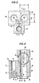
- FIG. 2 illustrates the base 36 of the pedestal as viewed from above.
- the shaft 40 which is not shown in Figure 2, would be positioned along the longitudinal axis of the base 36 and supported above a pair of lubricant and cap screw receiving passages 68 formed in the base which align with bores 50 in the shaft 40 when the shaft is in place.
- the upper surface 70 of the base portion 36 is contoured to have a concave semi-cylindrical shape as shown in Figures 1 and 3 to receive the bottom portion of the cylindrical shaft 40.
- the base 36 also includes a lubricant receiving extension 72 which both secures the lubricant supply rail against the nose portion 28 of the pedestal support surface 24 on the engine head and provides fluid communication between the lubricant supply rail and the shaft 40 through the pedestal base portion 36.
- the size and location of the lubricant and cap screw receiving passages 68 in the base is chosen to create an aligned annular lubricant flow passage around the circumference of each cap screw which extends from the holes 26 in the engine head through bores 50 in the shaft 40 when the base is installed on the engine head and the shaft is positioned on the base.
- the lubricant receiving extension 72 is provided with a threaded bore 74 which is located on the upper surface 76 of the extension 72. This threaded bore is not part of the pedestal lubrication circuit, but receives a mounting bolt (not shown) which secures a cover structrue (not shown) over all of the rocker arm assemblies mounted on the cylinder head.
- FIG 3 illustrates, in a side cross-sectional view taken along lines 3-3 of Figure 2, further details of the lubricant fluid circuit of the rocker support pedestal base 36.
- the lubricant receiving extension 72 includes a lubricant rail receiving and sealing surface 78 that is adapted to conform to the cross-sectional configuration of the lubricant supply rail 30.
- the sealing surface 78 sealingly engages the lubricant supply rail 30 between the nose portion 28 of pedestal mount 24 on the head and interior of the lubricant receiving extension 72.
- the height of the lubricant rail 30 is slightly greater than the height of the opening formed by sealing surface 78 so that when the rocker arm support assembly is mounted on the engine, the rail 30 will be biased toward the nose portion 28 to create a tight seal.
- a lubricant transfer bore 79 including a supply port 81, is located in the upper surface of the rail to convey lubricant from the rail lubricant passage 77 to an undercut 80 which communicates with a recess 82 formed in the lower surface 84 of the pedestal base portion 36. Recess 82 then communicates fluidically with lubricant and cap screw receiving passage 68 so that lubricant can be conveyed upwardly toward the shaft 40.
- FIGs 2 and 3 illustrate clearly, in addition, structure which enable the present rocker arm support assembly to achieve simultaneously the dual functions of conveying lubricant from the cylinder head to the rocker arms and precisely positioning the support assembly on the engine to insure the accurate alignment of the rocker arms relative to the shaft and the valve stems.
- the base 36 is provided with a pair of positioning projections or dowels 86 arranged to extend downwardly to engage counterbores (not shown) in the pedestal mount 24 which are positioned concentrically in relation to the bolt receiving holes 26.
- the central opening 88 of the positioning projection 86 shown in Figure 3 aligns generally with the passage 68.
- the primary function of the positioning projections 86 is to mount the rocker arm assembly on the engine so that the rocker arm rotational axis is properly aligned.
- projections 86 are formed to provide a tight fit in the direction indicated by arrows TF in Figure 2 and a loose fit in the perpendicular direction indicated by arrows LF in Figure 2. Providing a tight fit in only one direction not only reduces the costs associated with the need to machine parts precisely within minimal tolerances, but also, in this instance, guarantees the parallel alignment of the central axis of the rocker arm support shaft relative to the longitudinal axis of the engine as is required for minmizing wear between the ends of the rocker arms and the corresponding valve stems.
- the projections 86 also include slotted openings 90 formed therein which provide the necessary fluid connection between recess 82 and passage 68.
- Lubricant is thus conveyed from the rail 30 into the rocker arm pedestal base 36 through undercut 80 to the recess 82 and then through slotted openings 90 into passage 68, generally along the path shown by arrows 92 in Figure 2.
- Each passage 68 communicates at pedestal base upper surface 70 with a corresponding bore 50 in the rocker shaft 40 so that lubricant is transferred from passage 68 through bore 50 into the central longitudinal shaft passage 48.
- the lubricant within the shaft passage 48 is further conveyed to each rocker arm 42 laterally through shaft transfer bores 52.
- the components of the present rocker arm support pedestal are formed of hot pressed powdered metal, although other suitable materials are contemplated to be within the scope of the present invention.
- hot pressed powdered metal permits the formation of the undercut 80, the recess 82 and the slotted openings 90 by a simple, inexpensive molding/ pressing operation and, therefore, eliminates the need for this portion of the pedestal support assembly to be carefully and precisely machined.
- the lateral spacing of the rocker arms is dictated by the width of the rocker arm support assembly and particularly by the length of the shaft 40. This distance d, shown in Figure 4, is ultimately chosen to conform to the locations of the push rods which engage end 56 of each rocker arm. Because the right and left rocker arms are identical in configuration, the resulting positioning of the rocker arms along the shaft 40 separated by a distance d from each other causes the valve stems to engage ends 54 of the rocker arms at an offset location indicated by the x 94 on each rocker arm as illustrated in Figure 4. If the center of the insert pad 64 on end 54 of the rocker arm contacts the center of the valve stem, the motion of the valve stem is solely in an up and down direction. However, if the insert pad 64 contacts the valve stem at the offset location 94 shown in Figure 4, the load is moved outward and causes the valve stem to rotate. Valve rotation is thus automatically assured by this arrangement and additional structure to achieve proper valve rotation is, therefore, not required.
- the overall weight of the present rocker arm support assembly is further minimized by the use of a pedestal retainer clamp 38 ( Figure 1 and 3) to secure the shaft 40 to the pedestal base portion 36.
- the clamp 38 is not required to enclose shaft 40 completely, but extends downwardly over a small portion of the circumference of shaft 40.
- the clamp includes a concave shaft engaging surface 96 and a pair of centrally positioned bores 98 which are aligned longitudinally with bores 50 in the shaft, passages 68 in the pedestal base 36, central openings 88 in projections 86 and bolt receiving holes 26 in the pedestal mount 24 in the cylinder head.
- the rocker arm 42 is designed to function cooperatively with the rocker arm support assembly 10 in supplying an adequate, controlled flow of lubricant to the bearing surfaces, the valves and the push rods.
- Figures 4 and 5 illustrate features of the design which enable the rocker arms to achieve this objective.
- Each rocker arm 42 includes a lubricant supply passage 100 bored to extend from the outer surface 102 of the rocker arm to the interior, shaft contacting surface 104 of the rocker arm as can be seen clearly in Figure 5. Lubricant is supplied to supply passage 100 from outward shaft bores 52 when fluid communication is established between the conduits.
- Supply passage 100 on each rocker arm communicates wiht a lubricant distribution groove or trough 106 formed on the upper arcuate surface of each rocker arm which extends along the entire length of the rocker arm between ends 54 and 56.
- the position of the outlet port 101 of supply pasasge 100 in each groove 106 is carefully chosen to insure that an equal amount of oil flows to each end of the rocker arm during engine operation. The exact location was chosen following a consideration of the average time that the rocker arm spends in both the valve open and in the valve closed positions.
- the inlet 103 to supply passage 100 in interior rocker arm surface 104 will be aligned in fluid communication only intermittently with shaft bores 52 during engine operation.
- rocker arm lubricant supply passage within the rocker arm lubricant distribution groove which insures that an equal amount of lubricant is directed to each end of the rocker arm will depend on the exact shape of the rocker arm and will be different for intake and exhaust valve rocker arms of different shapes.
- rocker arm support assembly has been described herein primarily as a support for a pair of rocker arms. However, this is not intended to be limiting, and the present support assembly could be used to support a single rocker arm or more than two rocker arms, as required by the arrangement of the engine.
- the rocker arm support assembly of the present invention will find its primary application in an internal combustion engine which employs rocker arms rotatably journaled on a shaft to actuate intake and exhaust valves.
- the present rocker arm support assembly will insure the supply of the optimum amount of lubricant to these structures.
- the rocker arm support assembly of the present invention is simpler and less expensive to manufacture than previously known rocker arm support assemblies.
- rocker arm assembly may additionally be employed to achieve reductions in both engine weight and in the cost of manufacturing the components of the assembly.
Landscapes
- Engineering & Computer Science (AREA)
- Mechanical Engineering (AREA)
- General Engineering & Computer Science (AREA)
- Valve-Gear Or Valve Arrangements (AREA)
- Lubrication Of Internal Combustion Engines (AREA)
Applications Claiming Priority (2)
| Application Number | Priority Date | Filing Date | Title |
|---|---|---|---|
| US749753 | 1985-06-28 | ||
| US06/749,753 US4655177A (en) | 1985-06-28 | 1985-06-28 | Rocker arm support assembly |
Related Child Applications (1)
| Application Number | Title | Priority Date | Filing Date |
|---|---|---|---|
| EP88111222.1 Division-Into | 1986-06-24 |
Publications (2)
| Publication Number | Publication Date |
|---|---|
| EP0211503A1 EP0211503A1 (en) | 1987-02-25 |
| EP0211503B1 true EP0211503B1 (en) | 1990-08-16 |
Family
ID=25015040
Family Applications (2)
| Application Number | Title | Priority Date | Filing Date |
|---|---|---|---|
| EP86304866A Expired EP0211503B1 (en) | 1985-06-28 | 1986-06-24 | Support assembly |
| EP88111222A Withdrawn EP0305693A1 (en) | 1985-06-28 | 1986-06-24 | A rocker arm |
Family Applications After (1)
| Application Number | Title | Priority Date | Filing Date |
|---|---|---|---|
| EP88111222A Withdrawn EP0305693A1 (en) | 1985-06-28 | 1986-06-24 | A rocker arm |
Country Status (4)
| Country | Link |
|---|---|
| US (1) | US4655177A (enExample) |
| EP (2) | EP0211503B1 (enExample) |
| JP (1) | JPS623110A (enExample) |
| DE (1) | DE3673479D1 (enExample) |
Families Citing this family (26)
| Publication number | Priority date | Publication date | Assignee | Title |
|---|---|---|---|---|
| IT1186360B (it) * | 1985-11-04 | 1987-11-26 | Alfieri Maserati Spa Off | Motore a combustione interna ad elevate prestazioni |
| DE4326332A1 (de) * | 1993-08-05 | 1995-02-09 | Bayerische Motoren Werke Ag | Schwinghebel-Baugruppe mit miteinander verbindbaren Armen |
| GB2286014A (en) * | 1994-01-28 | 1995-08-02 | Perkins Ltd | Engine rocker arm lubrication |
| US5829397A (en) * | 1995-08-08 | 1998-11-03 | Diesel Engine Retarders, Inc. | System and method for controlling the amount of lost motion between an engine valve and a valve actuation means |
| US5636600A (en) * | 1995-10-31 | 1997-06-10 | Cummins Engine Company, Inc. | Rocker lever assembly for internal combustion engine |
| US5577470A (en) * | 1995-11-06 | 1996-11-26 | Ford Motor Company | Valve system for internal combustion engine |
| US5590627A (en) * | 1996-01-02 | 1997-01-07 | Chrysler Corporation | Fluid inletting and support structure for a variable valve assembly |
| DE19618416C2 (de) * | 1996-05-08 | 2003-11-13 | Ina Schaeffler Kg | Steckachse eines Betätigungshebels für einen Ventiltrieb einer Brennkraftmaschine |
| JPH1122435A (ja) * | 1997-07-01 | 1999-01-26 | Unisia Jecs Corp | エンジンの弁作動装置 |
| US5970932A (en) * | 1997-12-02 | 1999-10-26 | Panzer | Rocker arm assembly |
| US6138625A (en) * | 1998-03-17 | 2000-10-31 | Garrison; John Michael | Compact head assembly for internal combustion engine |
| US6230676B1 (en) * | 1999-04-23 | 2001-05-15 | Toledo Technologies Inc. | Interchangeable rocker arm assembly |
| US6484682B2 (en) | 2000-01-26 | 2002-11-26 | International Engine Intellectual Property Company, L.L.C. | Rocker arm assembly |
| US6444888B1 (en) | 2001-03-23 | 2002-09-03 | Vandruff Dean | Musical computer keyboard apparatus and method |
| DE20314366U1 (de) * | 2002-09-16 | 2004-05-19 | Perkins Engines Co. Ltd. | Zylinderkopf mit einem integral gegossenen Kipphebelwellenfussstück |
| US8087391B2 (en) * | 2003-06-26 | 2012-01-03 | Tores Lawrence S | Apparatus and methodology for rocker arm assembly |
| USD524823S1 (en) | 2005-01-27 | 2006-07-11 | John Michael Garrison | Motorcycle rocker box and cylinder head |
| US8251038B2 (en) | 2010-07-20 | 2012-08-28 | Caterpillar Inc. | Cylinder head rocker arm stand repair insert |
| US8607759B2 (en) | 2010-07-20 | 2013-12-17 | Caterpillar Inc. | Cylinder head rocker arm stand repair and process |
| DE102010047700A1 (de) * | 2010-10-06 | 2012-04-12 | Deutz Ag | Brennkraftmaschine |
| US8915224B2 (en) | 2010-12-18 | 2014-12-23 | Caterpillar Inc. | Rocker shaft shim |
| CN104088680A (zh) * | 2014-06-22 | 2014-10-08 | 中国北方发动机研究所(天津) | 一种框架摇臂 |
| CN111271147B (zh) * | 2020-04-10 | 2022-05-24 | 安徽航瑞航空动力装备有限公司 | 发动机气门摇臂安装结构 |
| US11905858B2 (en) | 2020-07-14 | 2024-02-20 | Powerhouse Engine Solutions Switzerland IP Holding GmbH | Systems and methods for rocker arm lubrication |
| US11306624B2 (en) * | 2020-07-16 | 2022-04-19 | Caterpillar Inc. | Valve actuation system for engine and valve lifter and rocker arm for same |
| EA202092392A2 (ru) * | 2020-07-16 | 2022-01-31 | Пауэрхаус Энджин Солюшнз Свитселанд АйПи Холдинг ГмбХ | Система двигателя внутреннего сгорания |
Family Cites Families (22)
| Publication number | Priority date | Publication date | Assignee | Title |
|---|---|---|---|---|
| US1281246A (en) * | 1917-06-16 | 1918-10-08 | Sturtevant Mill Co | Valve mechanism for internal-combustion engines. |
| US1784767A (en) * | 1928-08-24 | 1930-12-09 | Gen Motors Corp | Hydraulic valve mechanism |
| US1855166A (en) * | 1930-04-11 | 1932-04-19 | Gen Motors Corp | Rocker arm lubrication |
| GB355400A (en) * | 1930-06-05 | 1931-08-27 | Lea & Francis Ltd | Lubrication of the valve-operating mechanism of internal-combustion engines |
| US1871623A (en) * | 1930-09-09 | 1932-08-16 | Walter L Scott | Valve oiler |
| US2047446A (en) * | 1931-12-24 | 1936-07-14 | Taylor John Leonard | Scavenging tappet |
| US2224376A (en) * | 1936-11-18 | 1940-12-10 | Gen Motors Corp | Valve mechanism temperature regulator |
| US2288831A (en) * | 1940-10-10 | 1942-07-07 | Allis Chalmers Mfg Co | Engine rocker arm |
| GB709820A (en) * | 1950-12-26 | 1954-06-02 | Toledo Stamping & Mfg Company | Rocker arms for internal combustion engines |
| US2749888A (en) * | 1951-02-15 | 1956-06-12 | Henry J Kaiser Company | Internal combustion engine |
| US2976862A (en) * | 1959-11-09 | 1961-03-28 | Gen Motors Corp | Engine valve actuating mechanism |
| US3008544A (en) * | 1960-11-10 | 1961-11-14 | Krizman Mfg Co Inc | Lubricating system |
| US3251350A (en) * | 1963-05-20 | 1966-05-17 | Thompson Marion Lee | Rocker arm and mounting therefor |
| US3140699A (en) * | 1964-02-10 | 1964-07-14 | Jerry V Rassushin | Method for removing sediment from rocker arm shafts in gasoline engines and a device for facilitating the same |
| US4086887A (en) * | 1977-02-09 | 1978-05-02 | Schoonover Alan G | Rocker arm shaft support |
| JPS6115203Y2 (enExample) * | 1977-11-26 | 1986-05-12 | ||
| JPS606587Y2 (ja) * | 1980-12-30 | 1985-03-02 | ヤンマーディーゼル株式会社 | 弁腕注油装置 |
| JPS5816426U (ja) * | 1981-07-27 | 1983-02-01 | 日野自動車株式会社 | 内燃機関に使用されるシヤフト・サポ−ト |
| JPS5833365A (ja) * | 1981-08-21 | 1983-02-26 | Matsushita Electric Ind Co Ltd | フレ−ム同期信号検出回路 |
| US4505236A (en) * | 1982-06-01 | 1985-03-19 | Nissan Motor Company, Limited | Valve operating arrangement of an internal combustion engine |
| JPS5914906U (ja) * | 1982-07-21 | 1984-01-30 | 石川島芝浦機械株式会社 | ロツカ−ア−ム支持装置 |
| JPS5958109A (ja) * | 1982-09-27 | 1984-04-03 | Honda Motor Co Ltd | 動弁系の潤滑油供給構造 |
-
1985
- 1985-06-28 US US06/749,753 patent/US4655177A/en not_active Expired - Lifetime
-
1986
- 1986-06-24 DE DE8686304866T patent/DE3673479D1/de not_active Expired - Lifetime
- 1986-06-24 EP EP86304866A patent/EP0211503B1/en not_active Expired
- 1986-06-24 EP EP88111222A patent/EP0305693A1/en not_active Withdrawn
- 1986-06-27 JP JP61152587A patent/JPS623110A/ja active Granted
Also Published As
| Publication number | Publication date |
|---|---|
| DE3673479D1 (de) | 1990-09-20 |
| JPS623110A (ja) | 1987-01-09 |
| US4655177A (en) | 1987-04-07 |
| EP0305693A1 (en) | 1989-03-08 |
| EP0211503A1 (en) | 1987-02-25 |
| JPH0520561B2 (enExample) | 1993-03-19 |
Similar Documents
| Publication | Publication Date | Title |
|---|---|---|
| EP0211503B1 (en) | Support assembly | |
| US5746167A (en) | Valve lifter | |
| EP1119689B1 (en) | Valve train assembly | |
| CA1233714A (en) | Integral rocker arm hydraulic lifter and bearing assembly | |
| GB2349181A (en) | Interchangeable rocker arm assembly | |
| EP1046791B1 (en) | Rocker arm assembly lubrication | |
| US4505236A (en) | Valve operating arrangement of an internal combustion engine | |
| US5553583A (en) | Rocker arm lubrication arrangement | |
| JPS6212816Y2 (enExample) | ||
| US4653441A (en) | Engine rocker arm assembly | |
| CA1309625C (en) | Engine valve train module | |
| US4864983A (en) | Pushrod retainer | |
| CA2323933C (en) | Crankshaft bearing and bushing assembly | |
| EP0206809B1 (en) | Lubricant supply rail | |
| US5492085A (en) | Supported pushrod for internal combustion engines | |
| EP2756175B1 (en) | Lubricating valve train carrier | |
| EP0652356A1 (en) | Journal bearing oil diverter | |
| JPH0515546Y2 (enExample) | ||
| US7377246B2 (en) | Vertically oriented camshaft cap oil diverter | |
| KR100444880B1 (ko) | 캠 샤프트 저널부의 윤활을 위한 오일 공급 구조 | |
| JPS6315528Y2 (enExample) | ||
| JPS6038051Y2 (ja) | 燃料噴射ポンプ | |
| JPH0619776Y2 (ja) | カムシャフトロケーティングプレートの潤滑構造 | |
| JPS6146165Y2 (enExample) | ||
| JPH0625615Y2 (ja) | 内燃機関におけるカム軸の軸受装置 |
Legal Events
| Date | Code | Title | Description |
|---|---|---|---|
| PUAI | Public reference made under article 153(3) epc to a published international application that has entered the european phase |
Free format text: ORIGINAL CODE: 0009012 |
|
| AK | Designated contracting states |
Kind code of ref document: A1 Designated state(s): DE GB |
|
| 17P | Request for examination filed |
Effective date: 19870731 |
|
| 17Q | First examination report despatched |
Effective date: 19880105 |
|
| GRAA | (expected) grant |
Free format text: ORIGINAL CODE: 0009210 |
|
| AK | Designated contracting states |
Kind code of ref document: B1 Designated state(s): DE GB |
|
| REF | Corresponds to: |
Ref document number: 3673479 Country of ref document: DE Date of ref document: 19900920 |
|
| PLBE | No opposition filed within time limit |
Free format text: ORIGINAL CODE: 0009261 |
|
| STAA | Information on the status of an ep patent application or granted ep patent |
Free format text: STATUS: NO OPPOSITION FILED WITHIN TIME LIMIT |
|
| 26N | No opposition filed | ||
| REG | Reference to a national code |
Ref country code: GB Ref legal event code: IF02 |
|
| PGFP | Annual fee paid to national office [announced via postgrant information from national office to epo] |
Ref country code: GB Payment date: 20030619 Year of fee payment: 18 |
|
| PGFP | Annual fee paid to national office [announced via postgrant information from national office to epo] |
Ref country code: DE Payment date: 20030630 Year of fee payment: 18 |
|
| PG25 | Lapsed in a contracting state [announced via postgrant information from national office to epo] |
Ref country code: GB Free format text: LAPSE BECAUSE OF NON-PAYMENT OF DUE FEES Effective date: 20040624 |
|
| PG25 | Lapsed in a contracting state [announced via postgrant information from national office to epo] |
Ref country code: DE Free format text: LAPSE BECAUSE OF NON-PAYMENT OF DUE FEES Effective date: 20050101 |
|
| GBPC | Gb: european patent ceased through non-payment of renewal fee |
Effective date: 20040624 |