EP0211484B1 - Elektrische Wärmeplatten - Google Patents
Elektrische Wärmeplatten Download PDFInfo
- Publication number
- EP0211484B1 EP0211484B1 EP86304326A EP86304326A EP0211484B1 EP 0211484 B1 EP0211484 B1 EP 0211484B1 EP 86304326 A EP86304326 A EP 86304326A EP 86304326 A EP86304326 A EP 86304326A EP 0211484 B1 EP0211484 B1 EP 0211484B1
- Authority
- EP
- European Patent Office
- Prior art keywords
- plate
- unit according
- bezel
- heating
- heating unit
- Prior art date
- Legal status (The legal status is an assumption and is not a legal conclusion. Google has not performed a legal analysis and makes no representation as to the accuracy of the status listed.)
- Expired - Lifetime
Links
Images

Classifications
-
- H—ELECTRICITY
- H05—ELECTRIC TECHNIQUES NOT OTHERWISE PROVIDED FOR
- H05B—ELECTRIC HEATING; ELECTRIC LIGHT SOURCES NOT OTHERWISE PROVIDED FOR; CIRCUIT ARRANGEMENTS FOR ELECTRIC LIGHT SOURCES, IN GENERAL
- H05B3/00—Ohmic-resistance heating
- H05B3/68—Heating arrangements specially adapted for cooking plates or analogous hot-plates
- H05B3/74—Non-metallic plates, e.g. vitroceramic, ceramic or glassceramic hobs, also including power or control circuits
-
- F—MECHANICAL ENGINEERING; LIGHTING; HEATING; WEAPONS; BLASTING
- F24—HEATING; RANGES; VENTILATING
- F24C—DOMESTIC STOVES OR RANGES ; DETAILS OF DOMESTIC STOVES OR RANGES, OF GENERAL APPLICATION
- F24C7/00—Stoves or ranges heated by electric energy
- F24C7/06—Arrangement or mounting of electric heating elements
- F24C7/067—Arrangement or mounting of electric heating elements on ranges
Definitions
- This invention relates to electric hobs of the kind having at least one heating unit replaceably supported within an opening in a hob-plate, and more especially to heating units for use in such hobs.
- U.S. Patent No. 3636309 discloses a heating unit of the kind designed to be supported within an opening in a hob-plate, and having a heating surface provided by a plate of glass ceramic material, incorporating a bezel fitting over a peripheral region of the plate, a housing accommodating an insulating support structure having a surface which faces the plate and carries electric heating means, and a wall which surrounds the heating means and serves to space it from the plate, and a plurality of straps spaced around the unit and each anchored at one end to the bezel and at the other end to the housing, so as to clamp the bezel to the housing and thereby to form a substantially rigid unit.
- An object of the present invention is to provide a heating unit of this type which is capable of fitting more closely within a respective opening in a hob-plate, to provide the maximum practicable heating area.
- the invention is characterised in that the glass ceramic plate is sandwiched between the bezel and the wall of the insulating support structure, and in that the housing comprises a first part which carries the insulating support structure, a second part to which the straps are anchored and which is disposed beneath the first part, and compression spring means disposed in the space between the two parts and acting to urge the first part, together with the insulating support structure, towards the glass ceramic plate.
- the unit By forming the straps of relatively thin metal, preferably having a thickness of approximately 0.6 mm, the unit can be arranged to get closely within a respective opening in a hob, so as to provide the maximum practicable heating area.
- the straps are preferably provided with hooked ends which fit into openings in the bezel, and with openings at their opposite ends which fit over tags on the undersurface of the housing, the tags being bent over to secure the straps in position.
- Other means of anchoring the straps to the bezel and/or to the housing may be employed.
- edge of the glass ceramic plate is formed with a peripheral rebate on its upper surface so that the upper surface of the bezel is substantially flush with the upper surface of the plate.
- the bezel is formed with a downtumed outer rim which is arranged to engage the surface of the hob-plate in which the unit is fitted.
- the edge of the hob-plate opening is arranged to have an upward ridge which, on assembly, in conjunction with a downward projection on the bezel encloses an annular space within which is contained a resilient seal.
- a further seal may be contained in a peripheral rebate in the upper surface of the wall of the insulated support structure.
- a seal is preferably of plastics material such as PTFE.
- the invention includes an electric hob unit comprising a hob-plate fitted with one or more heating units in accordance with the first aspect of the invention.
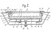
- the unit comprises a coiled wire electric heating element 1 stapled or otherwise secured in position on one surface of a circular support 2 of ceramic material.
- the heating element support 2 is accommodated within a metal casing 3 having a circular base 4 and, around it, an upstanding side wall 5, a soft ceramic blanket 6 being interposed between the support 2 and the base 4 of the casing in order to insulate the staples or other fasteners (not shown) electrically from the casing.
- the heating element 1 is surrounded by a ring 7 of ceramic material over which is fitted a glass ceramic plate 8, the ring serving to space the heating element from the lower surface of the plate.
- Insulated current supply terminals 10 are mounted on the side wall 5 of the case and are connected electrically to the ends of the heating element 1 in known manner.
- the glass ceramic plate 8 has a peripheral rebate in its upper surface, around which is fitted a metal bezel 9a in the form of a flat ring having a downward turned outer edge 11, an inner section shaped so as to be in contact with one or both walls of the peripheral rebate of the plate 8, and a cylindrical metal flange 13 surrounding the edge of the plate 8 and at least part of the ceramic ring 7.
- the edge 11 of the metal bezel 9a is in contact with the outer surface of the hob-plate 21.
- the hob-plate 21 has, near the edge of its opening 19, an upward annular ridge 27 such that when the hob unit is assembled the said upward ridge 27 and the downward outer edge enclose an annular space 28.
- a resilient seal 29 for the purpose of preventing liquids passing from the outside of the assembled unit to the inside of the assembled unit via the hob-plate-bezel interface.
- a seal 29 may, as shown in the diagram, be circular in cross section or may partially fill the space 28 in any other manner or completely fill it.
- the ceramic ring 7 has a peripheral rebate at its upper edge which contains a further seal 30.
- the seal 30 is preferably a plastics material (suitably P.T.F.E.) and is situated so as to prevent liquid passing through the interface between the plate 8 and the ring 7.
- the melting point of the said seal 30 is lower than the maximum working temperature within the heated chamber containing the element 1 it is desirable that the inner annular lip of the ring 7 is of sufficient thickness to prevent damage to the seal 30 from overheating.
- the heating unit comprises, in addition, a metal plate 32 located beneath the base of the casing 3, and in this case the metal bezel 9a is secured to the plate by means of three equally spaced straps 14.
- a metal plate 32 located beneath the base of the casing 3, and in this case the metal bezel 9a is secured to the plate by means of three equally spaced straps 14.
- Each strap has a hooked upper end 15 which passes through a respective opening 16 in the bezel flange 13, and an opening 17 adjacent its lower end which fits over a tag 43 pressed from the plate 32, which tag is subsequently bent inwards to secure the strap.
- the base of the casing 3 has welded to it three studs 31 which project downwards through holes in the plate, the shaft of each stud being surrounded by a helical compression spring 33 disposed in the space between the plate 32 and the casing 3.
- the attachment of the straps 14 to the plate 32 is such as to compress the springs 33 which causes the casing 3 and heating element support 2 with the ceramic ring 7 to be urged towards the glass ceramic plate 8, ensuring that the top edge of the ring 7 is held securely against the lower surface of the plate, forming a substantially rigid heating unit.
- a bridge member 23 is used to clamp the heating unit to the metal hob plate 21, the bridge member being secured by means of a nut 26 screwing on to a stud 25 carried by the metal plate 32.
- the straps 14 have a thickness of approximately 0.6 mm and a width of approximately 5.0 mm.
- a gasket may be disposed between the glass ceramic plate 8 and the bezel 9a, the material for such a gasket possibly being ceramic fibres.
- springs 33 are shown in the drawings as helical compression springs, they may be replaced by one or more waved washers or by a number of « Z » shaped springs.
- heating element 1 although shown in the drawings as a spiral electrical resistance heating element, may be of any suitable form such as one or more infra-red emitting lamps such as halogen lamps.
Landscapes
- Engineering & Computer Science (AREA)
- Chemical & Material Sciences (AREA)
- Ceramic Engineering (AREA)
- Combustion & Propulsion (AREA)
- Mechanical Engineering (AREA)
- General Engineering & Computer Science (AREA)
- Resistance Heating (AREA)
- Electric Stoves And Ranges (AREA)
Claims (13)
Applications Claiming Priority (2)
| Application Number | Priority Date | Filing Date | Title |
|---|---|---|---|
| GB8517401 | 1985-07-10 | ||
| GB858517401A GB8517401D0 (en) | 1985-07-10 | 1985-07-10 | Electric hobs |
Publications (2)
| Publication Number | Publication Date |
|---|---|
| EP0211484A1 EP0211484A1 (de) | 1987-02-25 |
| EP0211484B1 true EP0211484B1 (de) | 1990-01-24 |
Family
ID=10582065
Family Applications (1)
| Application Number | Title | Priority Date | Filing Date |
|---|---|---|---|
| EP86304326A Expired - Lifetime EP0211484B1 (de) | 1985-07-10 | 1986-06-06 | Elektrische Wärmeplatten |
Country Status (3)
| Country | Link |
|---|---|
| EP (1) | EP0211484B1 (de) |
| DE (1) | DE3668524D1 (de) |
| GB (2) | GB8517401D0 (de) |
Families Citing this family (7)
| Publication number | Priority date | Publication date | Assignee | Title |
|---|---|---|---|---|
| DE3918621A1 (de) * | 1989-06-07 | 1990-12-13 | Bosch Siemens Hausgeraete | Kochmulde fuer elektroherde, kochplatten oder dgl. |
| DE4039501A1 (de) * | 1990-12-11 | 1992-06-17 | Ego Elektro Blanc & Fischer | Elektrischer heizkoerper, insbesondere strahlheizkoerper |
| GB2277145B (en) * | 1993-04-13 | 1997-08-27 | Redring Electric Ltd | A hob |
| DE10132899C1 (de) * | 2001-07-06 | 2003-02-06 | Schott Glas | Kochstelle mit einer Glaskeramik-Schale, die eine abgesenkte, gekrümmte Heizfläche besitzt |
| KR100771628B1 (ko) * | 2006-05-11 | 2007-10-31 | 엘지전자 주식회사 | 전기레인지 |
| CN110679205B (zh) * | 2017-07-03 | 2022-08-12 | 伊莱克斯家用电器股份公司 | 烹饪灶具 |
| EP3426001B1 (de) * | 2017-07-03 | 2021-04-14 | Electrolux Appliances Aktiebolag | Kochfeld |
Family Cites Families (8)
| Publication number | Priority date | Publication date | Assignee | Title |
|---|---|---|---|---|
| DE608697C (de) * | 1931-03-14 | 1935-01-30 | Porzellanfabrik Kahla | Elektrische Heizplatte, bestehend aus zwei flach aufeinandergelegten keramischen Platten, deren obere als Abdeckplatte dient |
| FR1280278A (fr) * | 1961-02-08 | 1961-12-29 | Thomson Houston Comp Francaise | Perfectionnements aux éléments chauffants électriques |
| US3636309A (en) * | 1970-11-19 | 1972-01-18 | Gen Motors Corp | Ceramic-top cooking assembly fracture detector |
| US3686477A (en) * | 1971-08-06 | 1972-08-22 | Gen Electric | Mounting system for solid plate surface heating units |
| DE2222743C3 (de) * | 1972-05-09 | 1981-11-19 | Bosch-Siemens Hausgeräte GmbH, 7000 Stuttgart | Warmhalteplatte für die Kaffeekanne bei einer elektrischen Kaffeemaschine |
| CH577606A5 (de) * | 1974-01-18 | 1976-07-15 | Jenaer Glaswerk Schott & Gen | |
| DE7812144U1 (de) * | 1978-04-21 | 1978-09-07 | Jenaer Glaswerk Schott & Gen., 6500 Mainz | Glaskeramik-kochflaeche mit umlaufendem, dauerelastisch aufgeklebtem rahmen |
| DE3033828A1 (de) * | 1980-09-09 | 1982-04-29 | Fischer, Karl, 7519 Oberderdingen | Elektrokochplatte |
-
1985
- 1985-07-10 GB GB858517401A patent/GB8517401D0/en active Pending
-
1986
- 1986-06-06 DE DE8686304326T patent/DE3668524D1/de not_active Expired - Fee Related
- 1986-06-06 GB GB08613823A patent/GB2177578B/en not_active Expired
- 1986-06-06 EP EP86304326A patent/EP0211484B1/de not_active Expired - Lifetime
Also Published As
| Publication number | Publication date |
|---|---|
| GB2177578B (en) | 1988-11-02 |
| GB8613823D0 (en) | 1986-07-09 |
| EP0211484A1 (de) | 1987-02-25 |
| DE3668524D1 (de) | 1990-03-01 |
| GB2177578A (en) | 1987-01-21 |
| GB8517401D0 (en) | 1985-08-14 |
Similar Documents
| Publication | Publication Date | Title |
|---|---|---|
| US3686477A (en) | Mounting system for solid plate surface heating units | |
| US4032750A (en) | Flat plate heating unit with foil heating means | |
| CA2051861C (en) | Domestic cooking apparatus | |
| US3632983A (en) | Smooth surfaced, heated cooktop | |
| US4728779A (en) | PTC heating device | |
| US4447711A (en) | Electric heater | |
| US4410793A (en) | Electric hotplate | |
| US5051561A (en) | Radiant electric heaters | |
| EP0211484B1 (de) | Elektrische Wärmeplatten | |
| JPH01219428A (ja) | 自動表面装置用温度センサ組立体 | |
| JPH0220249B2 (de) | ||
| US3612827A (en) | Flat plate surface heating unit | |
| CN1258303C (zh) | 热敏控制装置以及加热器组件 | |
| US4717810A (en) | Electric hotplate | |
| GB2315204A (en) | A kettle containing a removable planar heating element | |
| US5968391A (en) | Modular radiant heating unit | |
| US1174030A (en) | Electric stove. | |
| EP0360859B1 (de) | Tempepaturgeregelte heizplatte | |
| US3268844A (en) | Temperature senser | |
| JPH0622861A (ja) | 電気調理器用温度センサー | |
| US7193192B2 (en) | Temperature-responsive device | |
| EP0948238A2 (de) | Elektrisches Strahlungsheizkörper | |
| GB2218605A (en) | Control means for an electric heater unit for an electric ceramic hob | |
| JPH0317123Y2 (de) | ||
| JPH061094Y2 (ja) | 電気湯沸し器 |
Legal Events
| Date | Code | Title | Description |
|---|---|---|---|
| PUAI | Public reference made under article 153(3) epc to a published international application that has entered the european phase |
Free format text: ORIGINAL CODE: 0009012 |
|
| AK | Designated contracting states |
Kind code of ref document: A1 Designated state(s): DE FR IT |
|
| 17P | Request for examination filed |
Effective date: 19870302 |
|
| 17Q | First examination report despatched |
Effective date: 19880919 |
|
| GRAA | (expected) grant |
Free format text: ORIGINAL CODE: 0009210 |
|
| AK | Designated contracting states |
Kind code of ref document: B1 Designated state(s): DE FR IT |
|
| PG25 | Lapsed in a contracting state [announced via postgrant information from national office to epo] |
Ref country code: IT Free format text: LAPSE BECAUSE OF FAILURE TO SUBMIT A TRANSLATION OF THE DESCRIPTION OR TO PAY THE FEE WITHIN THE PRE;WARNING: LAPSES OF ITALIAN PATENTS WITH EFFECTIVE DATE BEFORE 2007 MAY HAVE OCCURRED AT ANY TIME BEFORE 2007. THE CORRECT EFFECTIVE DATE MAY BE DIFFERENT FROM THE ONE RECORDED.SCRIBED TIME-LIMIT Effective date: 19900124 Ref country code: FR Effective date: 19900124 |
|
| REF | Corresponds to: |
Ref document number: 3668524 Country of ref document: DE Date of ref document: 19900301 |
|
| EN | Fr: translation not filed | ||
| PLBE | No opposition filed within time limit |
Free format text: ORIGINAL CODE: 0009261 |
|
| 26N | No opposition filed | ||
| PGFP | Annual fee paid to national office [announced via postgrant information from national office to epo] |
Ref country code: DE Payment date: 20010528 Year of fee payment: 16 |
|
| PG25 | Lapsed in a contracting state [announced via postgrant information from national office to epo] |
Ref country code: DE Free format text: LAPSE BECAUSE OF NON-PAYMENT OF DUE FEES Effective date: 20030101 |