EP0211035B1 - Homopolargenerator mit energiedichtheit - Google Patents
Homopolargenerator mit energiedichtheit Download PDFInfo
- Publication number
- EP0211035B1 EP0211035B1 EP86900890A EP86900890A EP0211035B1 EP 0211035 B1 EP0211035 B1 EP 0211035B1 EP 86900890 A EP86900890 A EP 86900890A EP 86900890 A EP86900890 A EP 86900890A EP 0211035 B1 EP0211035 B1 EP 0211035B1
- Authority
- EP
- European Patent Office
- Prior art keywords
- rotor
- current
- energy storage
- energy
- armature
- Prior art date
- Legal status (The legal status is an assumption and is not a legal conclusion. Google has not performed a legal analysis and makes no representation as to the accuracy of the status listed.)
- Expired - Lifetime
Links
- 230000005291 magnetic effect Effects 0.000 claims abstract description 34
- 238000004146 energy storage Methods 0.000 claims abstract description 30
- 238000003860 storage Methods 0.000 claims abstract description 7
- 230000004907 flux Effects 0.000 claims description 25
- 239000002131 composite material Substances 0.000 claims description 5
- 230000000712 assembly Effects 0.000 claims description 4
- 238000000429 assembly Methods 0.000 claims description 4
- 230000008878 coupling Effects 0.000 claims description 3
- 238000010168 coupling process Methods 0.000 claims description 3
- 238000005859 coupling reaction Methods 0.000 claims description 3
- 230000001143 conditioned effect Effects 0.000 claims 1
- 239000007769 metal material Substances 0.000 claims 1
- 238000013461 design Methods 0.000 description 18
- XEEYBQQBJWHFJM-UHFFFAOYSA-N Iron Chemical compound [Fe] XEEYBQQBJWHFJM-UHFFFAOYSA-N 0.000 description 11
- 230000005284 excitation Effects 0.000 description 10
- 230000001965 increasing effect Effects 0.000 description 9
- 239000000463 material Substances 0.000 description 8
- 230000001939 inductive effect Effects 0.000 description 7
- 239000004020 conductor Substances 0.000 description 5
- 238000010438 heat treatment Methods 0.000 description 5
- 239000004593 Epoxy Substances 0.000 description 4
- 238000013459 approach Methods 0.000 description 4
- 230000008901 benefit Effects 0.000 description 4
- 239000003302 ferromagnetic material Substances 0.000 description 4
- 239000011152 fibreglass Substances 0.000 description 4
- 229910002804 graphite Inorganic materials 0.000 description 4
- 239000010439 graphite Substances 0.000 description 4
- 229920000271 Kevlar® Polymers 0.000 description 3
- 238000006243 chemical reaction Methods 0.000 description 3
- 230000005294 ferromagnetic effect Effects 0.000 description 3
- 230000006872 improvement Effects 0.000 description 3
- 229910052742 iron Inorganic materials 0.000 description 3
- 239000004761 kevlar Substances 0.000 description 3
- 238000000926 separation method Methods 0.000 description 3
- IJGRMHOSHXDMSA-UHFFFAOYSA-N Atomic nitrogen Chemical compound N#N IJGRMHOSHXDMSA-UHFFFAOYSA-N 0.000 description 2
- OKTJSMMVPCPJKN-UHFFFAOYSA-N Carbon Chemical compound [C] OKTJSMMVPCPJKN-UHFFFAOYSA-N 0.000 description 2
- 229910000831 Steel Inorganic materials 0.000 description 2
- 229910052782 aluminium Inorganic materials 0.000 description 2
- XAGFODPZIPBFFR-UHFFFAOYSA-N aluminium Chemical compound [Al] XAGFODPZIPBFFR-UHFFFAOYSA-N 0.000 description 2
- 238000005520 cutting process Methods 0.000 description 2
- 238000005516 engineering process Methods 0.000 description 2
- 238000004519 manufacturing process Methods 0.000 description 2
- 229910052751 metal Inorganic materials 0.000 description 2
- 239000002184 metal Substances 0.000 description 2
- 239000007787 solid Substances 0.000 description 2
- 125000006850 spacer group Chemical group 0.000 description 2
- 239000010959 steel Substances 0.000 description 2
- ZOXJGFHDIHLPTG-UHFFFAOYSA-N Boron Chemical compound [B] ZOXJGFHDIHLPTG-UHFFFAOYSA-N 0.000 description 1
- RYGMFSIKBFXOCR-UHFFFAOYSA-N Copper Chemical compound [Cu] RYGMFSIKBFXOCR-UHFFFAOYSA-N 0.000 description 1
- 241000555745 Sciuridae Species 0.000 description 1
- 230000001154 acute effect Effects 0.000 description 1
- 230000003466 anti-cipated effect Effects 0.000 description 1
- 239000011230 binding agent Substances 0.000 description 1
- 229910052796 boron Inorganic materials 0.000 description 1
- 238000004364 calculation method Methods 0.000 description 1
- 238000007906 compression Methods 0.000 description 1
- 230000006835 compression Effects 0.000 description 1
- 238000010276 construction Methods 0.000 description 1
- 239000002826 coolant Substances 0.000 description 1
- 229910052802 copper Inorganic materials 0.000 description 1
- 239000010949 copper Substances 0.000 description 1
- 230000001419 dependent effect Effects 0.000 description 1
- 230000008030 elimination Effects 0.000 description 1
- 238000003379 elimination reaction Methods 0.000 description 1
- 239000003822 epoxy resin Substances 0.000 description 1
- 238000013213 extrapolation Methods 0.000 description 1
- 238000012432 intermediate storage Methods 0.000 description 1
- 239000007788 liquid Substances 0.000 description 1
- 238000002844 melting Methods 0.000 description 1
- 230000008018 melting Effects 0.000 description 1
- QSHDDOUJBYECFT-UHFFFAOYSA-N mercury Chemical compound [Hg] QSHDDOUJBYECFT-UHFFFAOYSA-N 0.000 description 1
- 229910052753 mercury Inorganic materials 0.000 description 1
- 150000002739 metals Chemical class 0.000 description 1
- 238000000034 method Methods 0.000 description 1
- 238000012986 modification Methods 0.000 description 1
- 230000004048 modification Effects 0.000 description 1
- 229910052757 nitrogen Inorganic materials 0.000 description 1
- 230000035699 permeability Effects 0.000 description 1
- 229920000647 polyepoxide Polymers 0.000 description 1
- 238000005381 potential energy Methods 0.000 description 1
- 230000000630 rising effect Effects 0.000 description 1
- 238000000638 solvent extraction Methods 0.000 description 1
- 239000013589 supplement Substances 0.000 description 1
- 238000012360 testing method Methods 0.000 description 1
- 239000002470 thermal conductor Substances 0.000 description 1
- 238000012546 transfer Methods 0.000 description 1
- 230000001052 transient effect Effects 0.000 description 1
- 238000005303 weighing Methods 0.000 description 1
Images

Classifications
-
- H—ELECTRICITY
- H02—GENERATION; CONVERSION OR DISTRIBUTION OF ELECTRIC POWER
- H02K—DYNAMO-ELECTRIC MACHINES
- H02K39/00—Generators specially adapted for producing a desired non-sinusoidal waveform
-
- H—ELECTRICITY
- H02—GENERATION; CONVERSION OR DISTRIBUTION OF ELECTRIC POWER
- H02K—DYNAMO-ELECTRIC MACHINES
- H02K31/00—Acyclic motors or generators, i.e. DC machines having drum or disc armatures with continuous current collectors
- H02K31/02—Acyclic motors or generators, i.e. DC machines having drum or disc armatures with continuous current collectors with solid-contact collectors
-
- H—ELECTRICITY
- H02—GENERATION; CONVERSION OR DISTRIBUTION OF ELECTRIC POWER
- H02K—DYNAMO-ELECTRIC MACHINES
- H02K55/00—Dynamo-electric machines having windings operating at cryogenic temperatures
- H02K55/06—Dynamo-electric machines having windings operating at cryogenic temperatures of the homopolar type
-
- H—ELECTRICITY
- H02—GENERATION; CONVERSION OR DISTRIBUTION OF ELECTRIC POWER
- H02K—DYNAMO-ELECTRIC MACHINES
- H02K7/00—Arrangements for handling mechanical energy structurally associated with dynamo-electric machines, e.g. structural association with mechanical driving motors or auxiliary dynamo-electric machines
- H02K7/02—Additional mass for increasing inertia, e.g. flywheels
- H02K7/025—Additional mass for increasing inertia, e.g. flywheels for power storage
-
- Y—GENERAL TAGGING OF NEW TECHNOLOGICAL DEVELOPMENTS; GENERAL TAGGING OF CROSS-SECTIONAL TECHNOLOGIES SPANNING OVER SEVERAL SECTIONS OF THE IPC; TECHNICAL SUBJECTS COVERED BY FORMER USPC CROSS-REFERENCE ART COLLECTIONS [XRACs] AND DIGESTS
- Y02—TECHNOLOGIES OR APPLICATIONS FOR MITIGATION OR ADAPTATION AGAINST CLIMATE CHANGE
- Y02E—REDUCTION OF GREENHOUSE GAS [GHG] EMISSIONS, RELATED TO ENERGY GENERATION, TRANSMISSION OR DISTRIBUTION
- Y02E40/00—Technologies for an efficient electrical power generation, transmission or distribution
- Y02E40/60—Superconducting electric elements or equipment; Power systems integrating superconducting elements or equipment
-
- Y—GENERAL TAGGING OF NEW TECHNOLOGICAL DEVELOPMENTS; GENERAL TAGGING OF CROSS-SECTIONAL TECHNOLOGIES SPANNING OVER SEVERAL SECTIONS OF THE IPC; TECHNICAL SUBJECTS COVERED BY FORMER USPC CROSS-REFERENCE ART COLLECTIONS [XRACs] AND DIGESTS
- Y02—TECHNOLOGIES OR APPLICATIONS FOR MITIGATION OR ADAPTATION AGAINST CLIMATE CHANGE
- Y02E—REDUCTION OF GREENHOUSE GAS [GHG] EMISSIONS, RELATED TO ENERGY GENERATION, TRANSMISSION OR DISTRIBUTION
- Y02E60/00—Enabling technologies; Technologies with a potential or indirect contribution to GHG emissions mitigation
- Y02E60/16—Mechanical energy storage, e.g. flywheels or pressurised fluids
Definitions
- a problem with self excited, air core HPG's such as that described in the Miller patent is the balance of energy required in the field coil for excitation versus the energy originally stored in the rotor.
- the energy required typically exceeds the energy that can be stored in rotor(s) fitting inside the coil and operating at conventional (about 200 m/s) surface speeds dictated by present day brush technology. This usually forces the rotors to be operated at higher than standard surface speeds in order to increase rotor energy density to the point needed to excite the field coil(s). This in turn compromises the durability of the HPG by causing the brushes to operate well above their capabilities.
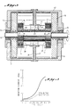
- the squirrel-cage HPG armature 18 is 0.25 m in diameter with an active length of 0.45 m. With an average flux density at the armature of 6.7 T the generator will develop 450 volts at half speed.
Landscapes
- Engineering & Computer Science (AREA)
- Power Engineering (AREA)
- Superconductive Dynamoelectric Machines (AREA)
- Permanent Magnet Type Synchronous Machine (AREA)
- Diaphragms For Electromechanical Transducers (AREA)
- Sealing Material Composition (AREA)
- Saccharide Compounds (AREA)
- Connection Of Motors, Electrical Generators, Mechanical Devices, And The Like (AREA)
Claims (5)
- Selbsterregender Luftkern (eisenloser) Homopolargenerator, der auf eine eingehende Rotationstreibung reagiert, um an einer Last einen Strom zu erzeugen mit:
einer Feldspulenanordnung (16, 17) zum Erzeugen eines magnetischen Feldes in einem inneren Bereich und zum Speichern eines gesammelten Stromes für die Last, wobei der gesammelte Strom mit zu dem erzeugten Magnetfeld beiträgt,
einem Rotor (18), der sich in dem inneren Bereich befindet und auf die eingehende Treibung und auf das magnetische Feld zum Erzeugen des Stromes reagiert,
einer Kontakteinrichtung (28, 29) zum Herstellen eines Kontaktes zwischen der Feldspulenanordnung (16, 17) und dem Rotor (18),
einer Energiespeichereinrichtung (12, 13), die mit dem Rotor (18) gekoppelt ist, um mit diesem zu rotieren, um Bewegungsenergie zu speichern, wobei die Energiespeicherkapazität der Speichereinrichtung unabhängig von dem Radius des Rotors erhalten wird,
und wobei die Kontakteinrichtung (28, 29) den induzierten Strom in Antwort auf die Rotation des Rotors (18) innerhalb des Feldes an die Feldspulenanordnung (16, 17) weiterleitet, um den Strom darin zu sammeln,
dadurch gekennzeichnet,
daß der Rotor (18) einen Anker aufweist, der hochleitfähige Schaltkreiselemente (23) in axialer Richtung aufweist, jedoch hochresistive Schaltkreiselemente (43) in Umfangsrichtung aufweist, und
ein Paar von beabstandeten Gleitringoberflächen (19), von denen jede sich in Umfangsrichtung des Ankers (18) erstreckt und elektrisch mit den Schaltkreiselementen (23) gekoppelt ist, wobei der Anker einen Radius an jeder Gleitringoberfläche aufweist, der dort die Rotoroberflächengeschwindigkeit bestimmt,
die Kontakteinrichtung (28, 29) ein Paar von leitfähigen Bürstenanordnungen, die mit der Feldspulenanordnung (16, 17) gekoppelt sind, ist, wobei jede der leitfähigen Bürstenanordnungen eine zugeordnete Gleitringoberfläche (19) kontaktiert und wobei die Bürstenanordnungen eine maximale Rotoroberflächengeschwindigkeit an der Gleitringoberfläche, bei der die Bürsten arbeiten können, aufweisen, und
wobei die in Umfangsrichtung resistiven Ankerschaltkreiselemente (43) eine Erhöhung der Entladungseffizienz des gesammelten Stromes an die Last zuläßt, indem die magnetische Kopplung des Ankers (18) mit dem Fluß des magnetischen Feldes während der Entladung des gesammelten Stromes in der Feldspulenanordnung (16, 17) an die Last reduziert wird. - Selbsterregender Luftkern-Homopolargenerator nach Anspruch 1, dadurch gekennzeichnet, daß die Energiespeichereinrichtung (12, 13) ein Energiespeicherrad, bestehend aus zusammengesetztem Material und mit einem Radius, der größer ist als der Radius des Rotors (18) aufweist, wobei das zusammengesetzte Material eine Erhöhung sowohl in der Stromsammeleffizienz, als auch in der Entladungseffizienz des gesammelten Stromes an die Last zuläßt, indem die magnetische Kopplung von Fluß von dem magnetischen Feld während des entsprechenden Sammelns und Abgebens des gesammelten Stromes an die Last in dem Speicherrad (12, 13) verhindert wird.
- Selbsterregender Luftkern-Homopolargenerator nach Anspruch 1 oder 2, dadurch gekennzeichnet, daß die Energiespeichereinrichtung (12, 13) des Generators ein Paar von Energiespeicherrädern umfaßt, wobei jeweils eines an jedem Ende des Rotors (18) angeordnet ist, um mit diesem zu rotieren und wobei das Rad aus zusammengesetztem Material besteht.
- Selbsterregender Luftkern-Homopolargenerator nach mindestens einem der vorhergehenden Ansprüche, dadurch gekennzeichnet, daß der Anker (18) eine Vielzahl von elektrisch leitfähigen Schaltkreisstangen (23) aufweist, welche sich axial entlang der äußeren Oberfläche des Ankers erstrecken und wobei jede von seiner benachbarten Stange durch eine isolierende Schicht (43) getrennt ist, wobei die Endoberflächen der Stangen für Gleitringoberflächen (19) ausgelegt sind, so daß, wenn die Bürstenanordnungen die Gleitringoberflächen kontaktieren, hochleitfähige Schaltkreispfade zwischen den Bürsten (28, 29) hergestellt werden, und wobei im Falle, daß der in der Feldspulenanordnung (16, 17) gesammelte Strom entladen wird, ein resistiver Schaltkreispfad in Umfangsrichtung entsteht, um den Verlust des magnetischen Feldes, wie es von dem Entladestrom von der Feldspule erzeugt wird, zu minimieren.
- Selbsterregender Luftkern-Homopolargenerator nach mindestens einem der vorhergehenden Ansprüche, dadurch gekennzeichnet, daß das Energiesspeicherrad (12, 13) zumindest teilweise aus nicht-metallischem Material gefertigt ist.
Priority Applications (1)
| Application Number | Priority Date | Filing Date | Title |
|---|---|---|---|
| AT86900890T ATE79989T1 (de) | 1985-01-09 | 1986-01-08 | Homopolargenerator mit energiedichtheit. |
Applications Claiming Priority (2)
| Application Number | Priority Date | Filing Date | Title |
|---|---|---|---|
| US68986885A | 1985-01-09 | 1985-01-09 | |
| US689868 | 1985-01-09 |
Publications (2)
| Publication Number | Publication Date |
|---|---|
| EP0211035A1 EP0211035A1 (de) | 1987-02-25 |
| EP0211035B1 true EP0211035B1 (de) | 1992-08-26 |
Family
ID=24770184
Family Applications (1)
| Application Number | Title | Priority Date | Filing Date |
|---|---|---|---|
| EP86900890A Expired - Lifetime EP0211035B1 (de) | 1985-01-09 | 1986-01-08 | Homopolargenerator mit energiedichtheit |
Country Status (8)
| Country | Link |
|---|---|
| US (1) | US4816709A (de) |
| EP (1) | EP0211035B1 (de) |
| JP (1) | JP2648302B2 (de) |
| AT (1) | ATE79989T1 (de) |
| AU (1) | AU5316686A (de) |
| CA (1) | CA1276672C (de) |
| DE (1) | DE3686531T2 (de) |
| WO (1) | WO1986004191A1 (de) |
Families Citing this family (22)
| Publication number | Priority date | Publication date | Assignee | Title |
|---|---|---|---|---|
| US4686405A (en) * | 1986-09-29 | 1987-08-11 | Westinghouse Electric Corp. | Homopolar dynamoelectric machine with externally actuated brushes |
| US4710660A (en) * | 1986-09-29 | 1987-12-01 | Westinghouse Electric Corp. | Solenoidal homopolar generator |
| US5532664A (en) * | 1989-07-18 | 1996-07-02 | Superconductivy, Inc. | Modular superconducting energy storage device |
| CA2059569C (en) * | 1991-01-17 | 1998-08-25 | Yoshihiro Ohnishi | Superconducting rotating machine, a superconducting coil, and a superconducting generator for use in a lighting equipment using solar energy |
| US5530309A (en) * | 1993-05-04 | 1996-06-25 | Board Of Regents, The University Of Texas System | Homopolar machine |
| WO1999049557A1 (en) * | 1998-03-23 | 1999-09-30 | Boris Mikhailovich Solodov | Method for generating a magnetic field |
| US6049150A (en) * | 1999-03-18 | 2000-04-11 | Chudleigh, Jr.; Walter Harold | Flywheel with electrically controlled input and output |
| US20030129855A1 (en) * | 2001-12-21 | 2003-07-10 | Douglas Richard E. | Current collector assembly and method |
| US7489060B2 (en) * | 2006-06-30 | 2009-02-10 | General Electric Company | Superconducting rotating machines with stationary field coils |
| US7492073B2 (en) * | 2006-06-30 | 2009-02-17 | General Electric Company | Superconducting rotating machines with stationary field coils |
| JP2009543540A (ja) * | 2006-07-07 | 2009-12-03 | ウィルスドルフ、ドリス | Mp−dマシン |
| US20080308464A1 (en) * | 2007-06-12 | 2008-12-18 | General Electric Company | Method and apparatus for regenerating adsorbents used in the purification of fuel |
| US7791229B2 (en) * | 2008-04-02 | 2010-09-07 | Goodzeit Carl L | Low heat leak, high torque power shaft for cryogenic machines |
| US7843094B2 (en) * | 2009-04-09 | 2010-11-30 | Goodzeit Carl L | Dual armature motor/generator with flux linkage between dual armatures and a superconducting field coil |
| US8084909B2 (en) * | 2009-04-09 | 2011-12-27 | Goodzeit Carl L | Dual armature motor/generator with flux linkage |
| US8356532B1 (en) * | 2009-05-25 | 2013-01-22 | Dailey Randall B | Hydraulically powered double flywheel alternator apparatus |
| RU2417504C1 (ru) * | 2010-02-24 | 2011-04-27 | Государственное образовательное учреждение высшего профессионального образования "Орловский государственный технический университет" (ОрелГТУ) | Супермаховиковый накопитель энергии |
| CN103229398B (zh) * | 2010-12-10 | 2016-03-30 | 三菱电机株式会社 | 旋转电机 |
| US9553463B2 (en) | 2011-10-12 | 2017-01-24 | Mechanical Energy Generating Systems, L.L.C. | Systems, methods, and apparatus for a homopolar generator charger with integral rechargeable battery |
| JP5856039B2 (ja) * | 2012-10-31 | 2016-02-09 | 株式会社神戸製鋼所 | フライホイール式電力貯蔵装置 |
| DE102016219680A1 (de) * | 2016-10-11 | 2018-04-12 | Siemens Aktiengesellschaft | Antriebssystem für ein Fahrzeug mit Verbrennungskraftmaschine und Treibstofftank |
| CN114123720B (zh) * | 2021-11-01 | 2025-03-18 | 南京邮电大学 | 多超导线圈旋转极靴式高温超导同步电机励磁系统 |
Family Cites Families (15)
| Publication number | Priority date | Publication date | Assignee | Title |
|---|---|---|---|---|
| FR656584A (fr) * | 1928-06-27 | 1929-05-10 | Dynamo homopolaire | |
| US3185873A (en) * | 1961-10-19 | 1965-05-25 | Morton M Rosenfeld | Generator and ventilation means |
| FR1326439A (fr) * | 1962-03-19 | 1963-05-10 | Centre Nat Rech Scient | Perfectionnements apportés aux procédés et machines pour engendrer des courants électriques très élevés |
| US3229133A (en) * | 1963-03-08 | 1966-01-11 | Sears Anthony | Direct current homopolar generators |
| GB1165538A (en) * | 1966-01-12 | 1969-10-01 | Internat Res And Dev Company L | Improvements in and relating to Homopolar Electric Machines |
| GB1337591A (de) * | 1970-02-05 | 1973-11-14 | ||
| US3683216A (en) * | 1971-02-24 | 1972-08-08 | Richard F Post | Inertial energy storage apparatus and system for utilizing the same |
| US3737694A (en) * | 1972-06-21 | 1973-06-05 | Univ Johns Hopkins | Fanned circular filament rotor |
| JPS49103106A (de) * | 1973-02-06 | 1974-09-30 | ||
| GB1475687A (en) * | 1973-05-25 | 1977-06-01 | Int Research & Dev Co Ltd | Homopolar dynamo-electric machines |
| GB1501087A (en) | 1975-05-14 | 1978-02-15 | Reyrolle Parsons Ltd | Pulse generators |
| US4032807A (en) * | 1976-01-06 | 1977-06-28 | General Electric Company | Inside-out motor/alternator with high inertia smooth rotor |
| US4150582A (en) * | 1976-08-02 | 1979-04-24 | Electric Power Research Institute, Inc. | Rotor ring for inertial energy storage rotor |
| US4086506A (en) * | 1976-08-05 | 1978-04-25 | The United States Of America As Represented By The United States Department Of Energy | Contra-rotating homopolar motor-generator for energy storage and return |
| US4503349A (en) * | 1983-07-29 | 1985-03-05 | Westinghouse Electric Corp. | Self-excited high current DC electrical pulse generator |
-
1986
- 1986-01-08 EP EP86900890A patent/EP0211035B1/de not_active Expired - Lifetime
- 1986-01-08 JP JP61500663A patent/JP2648302B2/ja not_active Expired - Lifetime
- 1986-01-08 WO PCT/US1986/000015 patent/WO1986004191A1/en not_active Ceased
- 1986-01-08 DE DE8686900890T patent/DE3686531T2/de not_active Expired - Fee Related
- 1986-01-08 AT AT86900890T patent/ATE79989T1/de not_active IP Right Cessation
- 1986-01-08 AU AU53166/86A patent/AU5316686A/en not_active Abandoned
- 1986-01-09 CA CA000499317A patent/CA1276672C/en not_active Expired - Lifetime
-
1987
- 1987-06-24 US US07/067,410 patent/US4816709A/en not_active Expired - Fee Related
Non-Patent Citations (2)
| Title |
|---|
| Revue Générale de l'Electricité, no. 12, December 1982, PARIS, (FR)C. Poubeau:"Les accumulateurs cinétiques d'énergie applications au véhicule électrique", pages 846-854, see page 848, right-hand column, lines 1-9; page 852, left-hand column, line 12- page 852, right-hand column, line 22; figures 3,4,10-12 * |
| Revue Générale de l'Electricité, volume 86, no. 3, March 1977, Paris, (FR) R: Brimaud et al.:"L'extrapolation à haute énergie des machines homopolaires sans fer", pages 195-200, see page 197, left-hand column, line 8 - page 198, left-hand column, line 9; figures 1,2 * |
Also Published As
| Publication number | Publication date |
|---|---|
| WO1986004191A1 (en) | 1986-07-17 |
| AU5316686A (en) | 1986-07-29 |
| US4816709A (en) | 1989-03-28 |
| DE3686531T2 (de) | 1993-01-21 |
| DE3686531D1 (de) | 1992-10-01 |
| EP0211035A1 (de) | 1987-02-25 |
| CA1276672C (en) | 1990-11-20 |
| JPS62501466A (ja) | 1987-06-11 |
| JP2648302B2 (ja) | 1997-08-27 |
| ATE79989T1 (de) | 1992-09-15 |
Similar Documents
| Publication | Publication Date | Title |
|---|---|---|
| EP0211035B1 (de) | Homopolargenerator mit energiedichtheit | |
| US4058746A (en) | Dynamoelectric machinery utilizing superconductive windings | |
| JP2020078243A (ja) | 入れ子型ロータオープンコアフライホイール | |
| EP1415385B1 (de) | Supraleitende drehmaschine mit einer durch bauart bestimmte anfangsreaktanz | |
| CA1113994A (en) | Homopolar machine for reversible energy storage and transfer systems | |
| EP2761729B1 (de) | Elektromechanische schwungräder | |
| US4126798A (en) | Superconductive winding | |
| EP1473815A2 (de) | Mehrpoligen supraleitenden dynamo-elektrischen Maschine | |
| GB1590222A (en) | Superconducting dynamoelectric machine having a liquid metal shield | |
| US5210452A (en) | Symmetric armature for high current, air-core pulsed alternators | |
| EP1593194B1 (de) | Rotoranordnung | |
| US4110648A (en) | Homopolar machine for reversible energy storage and transfer systems | |
| US5841211A (en) | Superconducting generator and system therefor | |
| US4710660A (en) | Solenoidal homopolar generator | |
| US4276507A (en) | Homopolar machine for reversible energy storage and transfer systems | |
| US5722303A (en) | Mixed-mu superconducting bearings | |
| US4042846A (en) | Unitary supporting structure for superconducting field assembly | |
| Mole et al. | Superconducting electrical machinery | |
| CN111332488A (zh) | 一种电磁弹射系统 | |
| US4710666A (en) | Homopolar generator with variable packing factor brushes | |
| Walls et al. | Improved energy density homopolar generator | |
| Harrowell | Preliminary studies of superconducting alternators | |
| Mole et al. | Design of a 10 MJ fast discharging homopolar machine | |
| Mole et al. | Design trends in homopolar machines since the mid-1960's | |
| GLEBOV et al. | DEVELOPMENT OF SUPERCONDUCTING GENERATORS AND MOTORS IN THE USSR |
Legal Events
| Date | Code | Title | Description |
|---|---|---|---|
| PUAI | Public reference made under article 153(3) epc to a published international application that has entered the european phase |
Free format text: ORIGINAL CODE: 0009012 |
|
| 17P | Request for examination filed |
Effective date: 19861203 |
|
| AK | Designated contracting states |
Kind code of ref document: A1 Designated state(s): AT BE CH DE FR GB IT LI LU NL SE |
|
| 17Q | First examination report despatched |
Effective date: 19891113 |
|
| GRAA | (expected) grant |
Free format text: ORIGINAL CODE: 0009210 |
|
| AK | Designated contracting states |
Kind code of ref document: B1 Designated state(s): AT BE CH DE FR GB IT LI LU NL SE |
|
| REF | Corresponds to: |
Ref document number: 79989 Country of ref document: AT Date of ref document: 19920915 Kind code of ref document: T |
|
| ITF | It: translation for a ep patent filed | ||
| REF | Corresponds to: |
Ref document number: 3686531 Country of ref document: DE Date of ref document: 19921001 |
|
| ET | Fr: translation filed | ||
| PLBE | No opposition filed within time limit |
Free format text: ORIGINAL CODE: 0009261 |
|
| STAA | Information on the status of an ep patent application or granted ep patent |
Free format text: STATUS: NO OPPOSITION FILED WITHIN TIME LIMIT |
|
| 26N | No opposition filed | ||
| EPTA | Lu: last paid annual fee | ||
| PGFP | Annual fee paid to national office [announced via postgrant information from national office to epo] |
Ref country code: GB Payment date: 19950103 Year of fee payment: 10 |
|
| PGFP | Annual fee paid to national office [announced via postgrant information from national office to epo] |
Ref country code: FR Payment date: 19950110 Year of fee payment: 10 Ref country code: DE Payment date: 19950110 Year of fee payment: 10 |
|
| PGFP | Annual fee paid to national office [announced via postgrant information from national office to epo] |
Ref country code: AT Payment date: 19950111 Year of fee payment: 10 |
|
| PGFP | Annual fee paid to national office [announced via postgrant information from national office to epo] |
Ref country code: CH Payment date: 19950113 Year of fee payment: 10 |
|
| PGFP | Annual fee paid to national office [announced via postgrant information from national office to epo] |
Ref country code: SE Payment date: 19950118 Year of fee payment: 10 |
|
| EAL | Se: european patent in force in sweden |
Ref document number: 86900890.4 |
|
| PGFP | Annual fee paid to national office [announced via postgrant information from national office to epo] |
Ref country code: NL Payment date: 19950131 Year of fee payment: 10 |
|
| PGFP | Annual fee paid to national office [announced via postgrant information from national office to epo] |
Ref country code: LU Payment date: 19950201 Year of fee payment: 10 |
|
| PGFP | Annual fee paid to national office [announced via postgrant information from national office to epo] |
Ref country code: BE Payment date: 19950302 Year of fee payment: 10 |
|
| PG25 | Lapsed in a contracting state [announced via postgrant information from national office to epo] |
Ref country code: LU Free format text: LAPSE BECAUSE OF NON-PAYMENT OF DUE FEES Effective date: 19960108 Ref country code: GB Effective date: 19960108 Ref country code: AT Effective date: 19960108 |
|
| PG25 | Lapsed in a contracting state [announced via postgrant information from national office to epo] |
Ref country code: SE Effective date: 19960109 |
|
| PG25 | Lapsed in a contracting state [announced via postgrant information from national office to epo] |
Ref country code: LI Effective date: 19960131 Ref country code: CH Effective date: 19960131 Ref country code: BE Effective date: 19960131 |
|
| BERE | Be: lapsed |
Owner name: BOARD OF REGENTS THE UNIVERSITY OF TEXAS SYSTEM Effective date: 19960131 |
|
| PG25 | Lapsed in a contracting state [announced via postgrant information from national office to epo] |
Ref country code: NL Effective date: 19960801 |
|
| GBPC | Gb: european patent ceased through non-payment of renewal fee |
Effective date: 19960108 |
|
| REG | Reference to a national code |
Ref country code: CH Ref legal event code: PL |
|
| PG25 | Lapsed in a contracting state [announced via postgrant information from national office to epo] |
Ref country code: FR Effective date: 19960930 |
|
| NLV4 | Nl: lapsed or anulled due to non-payment of the annual fee |
Effective date: 19960801 |
|
| PG25 | Lapsed in a contracting state [announced via postgrant information from national office to epo] |
Ref country code: DE Effective date: 19961001 |
|
| EUG | Se: european patent has lapsed |
Ref document number: 86900890.4 |
|
| REG | Reference to a national code |
Ref country code: FR Ref legal event code: ST |
|
| PG25 | Lapsed in a contracting state [announced via postgrant information from national office to epo] |
Ref country code: IT Free format text: LAPSE BECAUSE OF NON-PAYMENT OF DUE FEES;WARNING: LAPSES OF ITALIAN PATENTS WITH EFFECTIVE DATE BEFORE 2007 MAY HAVE OCCURRED AT ANY TIME BEFORE 2007. THE CORRECT EFFECTIVE DATE MAY BE DIFFERENT FROM THE ONE RECORDED. Effective date: 20050108 |