EP0210910A2 - Appareil de séparation cyclonaire à écoulement axial - Google Patents
Appareil de séparation cyclonaire à écoulement axial Download PDFInfo
- Publication number
- EP0210910A2 EP0210910A2 EP86401541A EP86401541A EP0210910A2 EP 0210910 A2 EP0210910 A2 EP 0210910A2 EP 86401541 A EP86401541 A EP 86401541A EP 86401541 A EP86401541 A EP 86401541A EP 0210910 A2 EP0210910 A2 EP 0210910A2
- Authority
- EP
- European Patent Office
- Prior art keywords
- tubular body
- downstream
- upstream
- core
- converging
- Prior art date
- Legal status (The legal status is an assumption and is not a legal conclusion. Google has not performed a legal analysis and makes no representation as to the accuracy of the status listed.)
- Withdrawn
Links
- 238000011144 upstream manufacturing Methods 0.000 claims abstract description 28
- 239000012530 fluid Substances 0.000 claims abstract description 15
- 239000002245 particle Substances 0.000 claims abstract description 14
- 230000007423 decrease Effects 0.000 claims abstract description 3
- 238000000926 separation method Methods 0.000 claims description 17
- 230000003247 decreasing effect Effects 0.000 claims description 8
- UYXAWHWODHRRMR-UHFFFAOYSA-N hexobarbital Chemical compound O=C1N(C)C(=O)NC(=O)C1(C)C1=CCCCC1 UYXAWHWODHRRMR-UHFFFAOYSA-N 0.000 claims description 2
- 239000000725 suspension Substances 0.000 claims 1
- 239000000428 dust Substances 0.000 description 4
- 230000001133 acceleration Effects 0.000 description 2
- 230000000694 effects Effects 0.000 description 1
- 230000002349 favourable effect Effects 0.000 description 1
- 239000007788 liquid Substances 0.000 description 1
- 230000005012 migration Effects 0.000 description 1
- 238000013508 migration Methods 0.000 description 1
- 230000002093 peripheral effect Effects 0.000 description 1
- 238000011084 recovery Methods 0.000 description 1
- 230000001105 regulatory effect Effects 0.000 description 1
- 239000007787 solid Substances 0.000 description 1
Images
Classifications
-
- B—PERFORMING OPERATIONS; TRANSPORTING
- B04—CENTRIFUGAL APPARATUS OR MACHINES FOR CARRYING-OUT PHYSICAL OR CHEMICAL PROCESSES
- B04C—APPARATUS USING FREE VORTEX FLOW, e.g. CYCLONES
- B04C3/00—Apparatus in which the axial direction of the vortex flow following a screw-thread type line remains unchanged ; Devices in which one of the two discharge ducts returns centrally through the vortex chamber, a reverse-flow vortex being prevented by bulkheads in the central discharge duct
Definitions
- the subject of the invention is a cyclonal axial flow device intended for the separation of solid or liquid particles suspended in a fluid and constituted by a tubular body comprising a converging upstream portion, a diverging downstream portion and an intermediate portion comprising openings for the evacuation of the separated particles, a core disposed in the axis of said tubular body and extending over the entire length of the tubular body, a vane for rotating the fluid to be purified placed at the inlet end of the tubular body , in the passage formed between the latter and the core, and straightening vanes arranged in said passage between the upstream end of said diverging portion and the outlet end of the tubular body.
- Devices of this type are generally very effective in separating particles whose size is equal to or greater than 10 microns. On the other hand, for particles of smaller dimensions their separation efficiency is lower.
- the object of the present invention is to improve the separation efficiency of these devices, in particular for particles whose dimensions are between 5 and 10 microns.
- the cyclone separation device object of the invention is characterized in that the section of the passage formed between the tubular body and the core has a progressively decreasing section, from upstream to downstream, in the converging portion of the tubular body, and a progressively increasing section, from upstream to downstream, between the upstream end of the divergent portion and the outlet end of the tubular body.
- the straightening vanes can be placed either at the downstream end of the divergent portion of the tubular body, or between its ends.
- the tubular body will comprise a cylindrical portion downstream of the straightening vanes and the core will comprise in this portion of the tubular body a portion whose section decreases progressively from upstream to downstream.
- the part of the core located downstream of the straightening vanes will be cylindrical.
- the openings for the evacuation of the separated particles may be formed by longitudinal slots cut in the downstream part of the converging portion of the tubular body, or in a cylindrical portion comprised between the converging and diverging portions.
- the rotation vane for the fluid to be treated may be placed in the converging portion of the tubular body, near its upstream end, or in a cylindrical portion of the tubular body provided upstream of the converging portion.
- the part of the nucleus extending along the converging portion tubular body may be cylindrical or have a decreasing cross section from upstream to downstream.
- the arrangements according to the invention make it possible to increase the separation efficiency by reducing the thickness of the peripheral boundary layer at the level of the dust evacuation slots and by regulating the profile of the speeds in the fluid stream, which has the effect to promote the migration of particles towards the periphery of the tubular body. They also make it possible to create a form favorable to the collection of dust when several devices of the type described are grouped in a box.
- the invention also makes it possible to reduce the speed of the fluid at the level of the rotation vane and, consequently, its wear.
- the acceleration of rotation in the convergent also considerably improves the separation of dust while maintaining a moderate level of turbulence thanks to the central core which suppresses axial detachments and return currents.
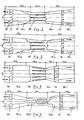
- Figures 1 to 4 of this drawing are views, partially in elevation and partially in section, of four cyclone separation with axial flow produced in accordance with the invention.
- These devices consist of a tubular body of revolution 10 inside which is placed an elongated core 12, of circular section, which extends over the entire length of the body 10 and whose axis coincides with that of the latter.
- the front end of the core 12 is profiled.
- Rotation vanes 14 are provided at the upstream end of the device through which between the fluid to be purified and rectifying vanes 16 are arranged in its downstream part; these blades also serve to support and center the core in the tubular body of the device.
- the body of the apparatus successively comprises, moving in the direction of flow of the fluid indicated by the arrows, an upstream, frustoconical and convergent portion 10a, an intermediate cylindrical portion 10b and a downstream, frustoconical and divergent portion 10c.
- the part 12a of the core between the rotation blades 14 and the connection plane of the portions 10b and 10c has a cylindrical shape
- the part 12b between this plane and the straightening blades 16 has a frustoconical shape, its section increasing regularly from upstream to downstream
- the part 10c located downstream of the blades 16 also has a cylindrical shape.
- Slots longitudinal 18 are cut in the portion 10b of the tubular body 10 for the evacuation of the particles separated from the fluid.
- the portion 10b has been eliminated and replaced by an extension of the frustoconical portion 10a in which the slots are formed 18.
- the shapes of the portion 10c and of the core 12 are the same as in the device of figure 1.
- the tubular body successively comprises, from upstream to downstream, a cylindrical portion 10d, a converging frustoconical portion 10a, a diverging frustoconical portion 10c and a cylindrical portion 10e.
- the rotation vanes 14 are located in the portion 10d, the straightening vanes 16 are located at the connection of the portions 10c and 10e and the slots 18 are formed in the downstream part of the portion 10a.
- the core 12 has a cylindrical shape between the blades 14 and the connection plane of the portions 10a and 10c (part 12a), a frustoconical shape, with increasing section, in the portion 10c (part 12b) and a frustoconical shape, with decreasing section , in the 10th portion (part 12c ').
- the body of the device successively comprises a short portion cylindrical 10d, a converging frustoconical portion 10a, a cylindrical portion 10b, a diverging frustoconical portion 10c and a cylindrical portion 10e.
- the blades 14 are arranged in the portion 10d, immediately upstream of the connection plane of the portions 10a and 10d, the blades 16 are placed in the cylindrical portion 10e, immediately downstream of the connection plane of the portions 10c and 10e and the slots 18 are provided in the downstream part of the cylindrical portion 10b.
- the part 12a 'of the core between the vanes 14 and the connection plane of the portions 10a and 10b of the body of the apparatus has a frustoconical shape, with decreasing section
- the part 12a "located in the portion 10b has a cylindrical shape
- the part 12b located in the portion 10c has a frustoconical shape, with increasing section
- the part 12c 'situated downstream of the straightening vanes 16 has a frustoconical shape, with decreasing section.
- This device will be used in the case of difficult separations because it allows, thanks to the narrowing of the core in the portions 10a and 10b, to obtain a greater centrifugal acceleration for the same radial size of the device.
- the section of the passage formed between the tubular body and the core, in the converging portion 10a has a progressively decreasing section, from upstream to downstream, so as to accelerate the rotation of the fluid and improve the separation dust.
- the section of the passage formed between the tubular body and the core has a progressively increasing section from upstream to downstream, which allows maximum recovery of the kinetic energy of the fluid and, therefore, a significant reduction in pressure drop.
- the angle at the top of the frustoconical part 12b of the core can be equal to or greater than that of the portion 10c of the tubular body, but in all cases the cross section of the passage formed between them increases from upstream to downstream.
Abstract
Description
- L'invention a pour objet un appareil cyclonaire à écoulement axial destiné à la séparation des particules solides ou liquides en suspension dans un fluide et constitué par un corps tubulaire comprenant une portion amont convergente, une portion aval divergente et une portion intermédiaire comportant des ouvertures pour l'évacuation des particules séparées, un noyau disposé dans l'axe dudit corps tubulaire et s'étendant sur toute la longueur du corps tubulaire, un aubage de mise en rotation du fluide à épurer placé à l'extrémité d'entrée du corps tubulaire, dans le passage ménagé entre ce dernier et le noyau, et des aubes de redressement disposées dans ledit passage entre l'extrémité amont de ladite portion divergente et l'extrémité de sortie du corps tubulaire. Les appareils de ce type sont en général très efficaces pour séparer des particules dont la grosseur est égale ou supérieure à 10 microns. Par contre, pour des particules de dimensions inférieures leur efficacité de séparation est moindre.
- Le but de la présente invention est d'améliorer l'efficacité de séparation de ces appareils notamment pour des particules dont les dimensions sont comprises entre 5 et 10 microns.
- L'appareil de separation cyclonaire objet de l'invention est caracterisé en ce que la section du passage ménagé entre le corps tubulaire et le noyau a une section progressivement décroissante, de l'amont vers l'aval, dans la portion convergente du corps tubulaire, et une section progressivement croissante, de l'amont vers l'aval, entre l'extrémité amont de la portion divergente et l'extrémité de sortie du corps tubulaire. Les aubes de redressement pourront être placées soit à l'extrémité aval de la portion divergente du corps tubulaire, soit entre ses extrémités. Dans le premier cas, le corps tubulaire comportera une portion cylindrique en aval des aubes de redressement et le noyau comprendra dans cette portion du corps tubulaire une partie dont la section décroit progressivement de l'amont vers l'aval. Dans le second cas, la partie du noyau située en aval des aubes de redressement sera cylindrique.
- Les ouvertures pour l'évacuation des particules séparées pourront être constituées par des fentes longitudinales découpées dans la partie aval de la portion convergente du corps tubulaire, ou dans une portion cylindrique comprise entre les portions convergente et divergente.
- L'aubage de mise en rotation du fluide à traiter pourra être placé dans la portion convergente du corps tubulaire, près de son extrémité amont, ou dans une portion cylindrique du corps tubulaire prévue à l'amont de la portion convergente.
- La partie du noyau s'étendant le long de la portion convergente du corps tubulaire pourra être cylindrique ou avoir une section droite décroissante de l'amont vers l'aval.
- Les dispositions selon l'invention permettent d'augmenter le rendement de séparation en diminuant l'épaisseur de la couche limite périphérique au niveau des fentes d'évacuation des poussières et en régularisant le profil des vitesses dans la veine fluide, ce qui a pour effet de favoriser la migration des particules vers la périphérie du corps tubulaire. Elles permettent en outre de créer une forme favorable à la collecte des poussiéres lorsque plusieurs appareils du type décrit sont groupés dans un caisson. Pour une même efficacité de séparation l'invention permet aussi de réduire la vitesse du fluide au niveau de l'aubage de mise en rotation et, par conséquent, son usure. L'accélération de la rotation dans le convergent améliore aussi considérablement la séparation des poussières tout en conservant un niveau de turbulence modéré grâce au noyau central qui supprime les décollements axiaux et les courants de retour.
- La description qui suit se réfère au dessin l'accompagnant qui montre, à titre d'exemple non l imitatif, plusieurs formes de réalisation de l'invention.
- Les figures 1 à 4 de ce dessin sont des vues, partiellement en élévation et partiellement en coupe, de quatre appareils de séparation cyclonaire à écoulement axial réalisés conformément à l'invention.
- Ces appareils sont constitués par un corps tubulaire de révolution 10 à l'intérieur duquel est placé un noyau allongé 12, à section circulaire, qui s'étend sur toute la longueur du corps 10 et dont l'axe coïncide avec celui de ce dernier. L'extrémité avant du noyau 12 est profilée. Des aubes 14 de mise en rotation sont prévues à l'extrémité amont de l'appareil par où entre le fluide à épurer et des aubes de redressement 16 sont disposées dans sa partie aval ; ces aubes servent en outre à supporter et à centrer le noyau dans le corps tubulaire de l'appareil.
- Dans la forme de réalisation de la figure 1, le corps de l'appareil comprend successivement, en se déplaçant dans le sens d'écoulement du fluide indiqué par les flèches, une portion amont, tronconique et convergente 10a, une portion intermédiaire cylindrique 10b et une portion aval, tronconique et divergente 10c. La partie 12a du noyau comprise entre les aubes de mise en rotation 14 et le plan de raccordement des portions 10b et 10c, a une forme cylindrique, la partie 12b comprise entre ce plan et les aubes de redressment 16 a une forme tronconique, sa section croissant régulièrement de l'amont vers l'aval, et la partie 10c située à l'aval des aubes 16 a également une forme cylindrique. Des fentes longitudinales 18 sont découpées dans la portion 10b du corps tubulaire 10 pour l'évacuation des particules séparées du fluide.
- Dans la forme de réalisation de la figure 2, la portion 10b a été supprimée et remplacée par un prolongement de la portion tronconique 10a dans lequel sont formées les fentes 18. Les formes de la portion 10c et du noyau 12 sont les mêmes que dans l'appareil de la figure 1.
- Dans l'appareil de la figure 3, le corps tubulaire comprend successivement, de l'amont vers l'aval, une portion cylindrique 10d, une portion tronconique convergente 10a, une partie tronconique divergente 10c et une portion cylindrique 10e. Les aubes de mise en rotation 14 sont situées dans la portion 10d, les aubes de redressement 16 sont situées au raccordement des portions 10c et 10e et les fentes 18 sont formées dans la partie aval de la portion 10a. Le noyau 12 a une forme cylindrique entre les aubes 14 et le plan de raccordement des portions 10a et 10c (partie 12a), une forme tronconique, à section croissante, dans la portion 10c (partie 12b) et une forme tronconique, à section décroissante, dans la portion 10e (partie 12c').
- Dans la forme de réalisation de la figure 4, le corps de l'appareil comprend successivement une courte portion cylindrique 10d, une portion tronconique convergente 10a, une portion cylindrique 10b, une portion tronconique divergente 10c et une portion cylindrique 10e. Les aubes 14 sont disposées dans la portion 10d, immédiatement en amont du plan de raccordement des portions 10a et 10d, les aubes 16 sont placées dans la portion cylindrique 10e, immédiatement en aval du plan de raccordement des portions 10c et 10e et les fentes 18 sont prévues dans la partie aval de la portion cylindrique 10b. La partie 12a' du noyau comprise entre les aubes 14 et le plan de raccordement des portions 10a et 10b du corps de l'appareil a une forme tronconique, à section décroissante, la partie 12a" située dans la portion 10b a une forme cylindrique, la partie 12b située dans la portion 10c a une forme tronconique, à section croissante et la partie 12c' située en aval des aubes de redressement 16 a une forme tronconique, à section décroissante. Cet appareil sera utilisé dans le cas de séparations difficiles car il permet, grâce au rétrécissement du noyau dans les portions 10a et 10b, d'obtenir une accélération centrifuge supérieure pour un même encombrement radial de l'appareil.
- La conc eption particulière de ces appareils permet de créer une force centrifuge élevée dans la zone des fentes 16 avec une perte de charge relativement faible. Par ailleurs, la disposition des fentes 16 dans une portion rétrécie du corps de l'appareil facilite la sortie des particules et leur collecte lorsque plusieurs appareils sont disposés côte à côte dans un caisson.
- Dans tous ces appareils, la section du passage ménagé entre le corps tubulaire et le noyau, dans la portion convergente 10a a une section progressivement décroissante, de l'amont vers l'aval, de façon à accélérer la rotation du fluide et améliorer la séparation des poussières. Dans la partie aval de l'appareil, la section du passage ménagé entre le corps tubulaire et le noyau a une section progresivement croissante de l'amont vers l'aval, ce qui permet une récupération maximale de l'énergie cinétique du fluide et, par conséquent, une réduction sensible de la perte de charge. L'angle au sommet de la partie tronconique 12b du noyau peut être égale ou supérieure à celui de la portion 10c du corps tubulaire, mais dans tous les cas la section droite du passage ménagé entre eux croit de l'amont vers l'aval.
Claims (8)
Applications Claiming Priority (2)
| Application Number | Priority Date | Filing Date | Title |
|---|---|---|---|
| FR8511445 | 1985-07-26 | ||
| FR8511445A FR2585266B1 (fr) | 1985-07-26 | 1985-07-26 | Appareil de separation cyclonaire a ecoulement axial |
Publications (2)
| Publication Number | Publication Date |
|---|---|
| EP0210910A2 true EP0210910A2 (fr) | 1987-02-04 |
| EP0210910A3 EP0210910A3 (fr) | 1988-04-13 |
Family
ID=9321671
Family Applications (1)
| Application Number | Title | Priority Date | Filing Date |
|---|---|---|---|
| EP86401541A Withdrawn EP0210910A3 (fr) | 1985-07-26 | 1986-07-10 | Appareil de séparation cyclonaire à écoulement axial |
Country Status (2)
| Country | Link |
|---|---|
| EP (1) | EP0210910A3 (fr) |
| FR (1) | FR2585266B1 (fr) |
Cited By (6)
| Publication number | Priority date | Publication date | Assignee | Title |
|---|---|---|---|---|
| NL1010478C2 (nl) * | 1998-11-04 | 2000-05-08 | Cds Engineering B V | Inrichting voor het behandelen van een gas/vloeistofmengsel. |
| WO2003066195A1 (fr) * | 2002-02-08 | 2003-08-14 | Norsk Hydro Asa | Dispositif de transformation d'ecoulement gazeux/liquide en ecoulement laminaire ou stratifie |
| EP1512453A1 (fr) * | 2003-08-30 | 2005-03-09 | Mann+Hummel Gmbh | Dispositif pour la séparation des particules dans un flux de média |
| EP1974790A1 (fr) * | 2007-03-26 | 2008-10-01 | Twister B.V. | Séparateur de fluide de cyclone |
| WO2010090510A1 (fr) * | 2009-02-05 | 2010-08-12 | Twister B.V. | Séparateur de fluide cyclonique à multiples étages |
| NL2028048A (en) * | 2020-06-16 | 2022-01-19 | Univ China Petroleum | Full-swirl supersonic separation device |
Citations (5)
| Publication number | Priority date | Publication date | Assignee | Title |
|---|---|---|---|---|
| US2201301A (en) * | 1937-03-30 | 1940-05-21 | Western Precipitation Corp | Centrifugal separating device |
| US2370629A (en) * | 1943-06-02 | 1945-03-06 | William R Appeldoorn | Dust precipitator |
| US2487633A (en) * | 1947-01-29 | 1949-11-08 | Jr Joseph Breslove | Separator |
| GB711304A (en) * | 1951-02-23 | 1954-06-30 | Svenska Flaektfabriken Ab | Device for separating dust |
| FR1069071A (fr) * | 1952-10-27 | 1954-07-05 | Airmeca | Perfectionnements aux capteurs de particules contenues dans des fluides |
-
1985
- 1985-07-26 FR FR8511445A patent/FR2585266B1/fr not_active Expired - Fee Related
-
1986
- 1986-07-10 EP EP86401541A patent/EP0210910A3/fr not_active Withdrawn
Patent Citations (5)
| Publication number | Priority date | Publication date | Assignee | Title |
|---|---|---|---|---|
| US2201301A (en) * | 1937-03-30 | 1940-05-21 | Western Precipitation Corp | Centrifugal separating device |
| US2370629A (en) * | 1943-06-02 | 1945-03-06 | William R Appeldoorn | Dust precipitator |
| US2487633A (en) * | 1947-01-29 | 1949-11-08 | Jr Joseph Breslove | Separator |
| GB711304A (en) * | 1951-02-23 | 1954-06-30 | Svenska Flaektfabriken Ab | Device for separating dust |
| FR1069071A (fr) * | 1952-10-27 | 1954-07-05 | Airmeca | Perfectionnements aux capteurs de particules contenues dans des fluides |
Cited By (18)
| Publication number | Priority date | Publication date | Assignee | Title |
|---|---|---|---|---|
| WO2000025931A1 (fr) * | 1998-11-04 | 2000-05-11 | Spark Technologies And Innovations N.V. | Dispositif servant a traiter un melange de gaz et de liquide |
| US7163626B1 (en) | 1998-11-04 | 2007-01-16 | Spark Technologies And Innovations N.V. | Device for treating a gas/liquid mixture |
| NL1010478C2 (nl) * | 1998-11-04 | 2000-05-08 | Cds Engineering B V | Inrichting voor het behandelen van een gas/vloeistofmengsel. |
| US7559975B2 (en) | 2002-02-08 | 2009-07-14 | Norsk Hydro Asa | Process for transforming gas/liquid flow into laminar or stratified flow |
| WO2003066195A1 (fr) * | 2002-02-08 | 2003-08-14 | Norsk Hydro Asa | Dispositif de transformation d'ecoulement gazeux/liquide en ecoulement laminaire ou stratifie |
| CN1308056C (zh) * | 2002-02-08 | 2007-04-04 | 诺尔斯海德公司 | 将气/液流转化成层流或片流的装置 |
| AU2003206266B2 (en) * | 2002-02-08 | 2008-07-17 | Equinor Energy As | Device for the transformation of gas/liquid flow to laminar or stratified flow |
| EP1512453A1 (fr) * | 2003-08-30 | 2005-03-09 | Mann+Hummel Gmbh | Dispositif pour la séparation des particules dans un flux de média |
| US7258727B2 (en) | 2003-08-30 | 2007-08-21 | Mann & Hummel Gmbh | Apparatus for separating particles from a flowing medium |
| EP1974790A1 (fr) * | 2007-03-26 | 2008-10-01 | Twister B.V. | Séparateur de fluide de cyclone |
| WO2008116732A1 (fr) * | 2007-03-26 | 2008-10-02 | Twister B.V. | Séparateur cyclonique de liquide |
| CN101678257B (zh) * | 2007-03-26 | 2011-08-24 | 缠绕机公司 | 旋流分离器 |
| AU2008231954B2 (en) * | 2007-03-26 | 2012-01-19 | Twister B.V. | Cyclonic fluid separator |
| US8475555B2 (en) | 2007-03-26 | 2013-07-02 | Twister B.V. | Cyclonic fluid separator |
| WO2010090510A1 (fr) * | 2009-02-05 | 2010-08-12 | Twister B.V. | Séparateur de fluide cyclonique à multiples étages |
| CN102369407B (zh) * | 2009-02-05 | 2015-01-28 | 缠绕机公司 | 多级旋流分离器 |
| US9034082B2 (en) | 2009-02-05 | 2015-05-19 | Twister B.V. | Multistage cyclonic fluid separator |
| NL2028048A (en) * | 2020-06-16 | 2022-01-19 | Univ China Petroleum | Full-swirl supersonic separation device |
Also Published As
| Publication number | Publication date |
|---|---|
| FR2585266B1 (fr) | 1990-05-11 |
| FR2585266A1 (fr) | 1987-01-30 |
| EP0210910A3 (fr) | 1988-04-13 |
Similar Documents
| Publication | Publication Date | Title |
|---|---|---|
| EP0028996B1 (fr) | Perfectionnements aux séparateurs centrifuges du genre cyclone | |
| ES2238395T3 (es) | Aparato para limpieza ciclonica de fluido. | |
| EP1916385B1 (fr) | Nageoire de plateforme de soufflante | |
| EP2147710B1 (fr) | Dispositif de séparation de particules solides de l'eau et installation hydraulique comprenant un tel dispositif | |
| EP0068002B1 (fr) | Etage de turbine | |
| EP0228097A2 (fr) | Séparateur tournant à vortex pour liquide hétérogéne | |
| FR2645184A1 (fr) | Appareil de fluidisation, de degazage et de pompage d'une suspension d'une matiere cellulosique fibreuse | |
| EP0210910A2 (fr) | Appareil de séparation cyclonaire à écoulement axial | |
| KR0155956B1 (ko) | 운동 에너지를 압력 에너지로 변환하기 위한 장치를 가진 원심 분리기 | |
| FR2588778A1 (fr) | Separateur a vortex liquide | |
| WO2013132190A1 (fr) | Générateurs de vortex placés dans le canal inter-aubes d'un redresseur de compresseur | |
| BE440285A (fr) | ||
| EP0341553A1 (fr) | Pompe centrifuge | |
| FR2681259A1 (fr) | Cellule cyclonique a entree axiale et passage direct et appareil d'epuration de fluide en faisant application. | |
| EP0082775B1 (fr) | Aspirateur statique de fluide gazeux perfectionné | |
| FR2757210A1 (fr) | Echappement centrifuge de turbine a deflecteur cambre | |
| FR2613956A1 (fr) | Procede et dispositif de separation centrifuge d'un melange de plusieurs phases | |
| FR2626322A1 (fr) | Roue a ailettes de compresseur centrifuge | |
| EP3174637B1 (fr) | Dispositif de séparation cyclonique comprenant deux cyclones reliés par une unité de canalisation optimisée | |
| BE465361A (fr) | ||
| FR2660580A1 (fr) | Dispositif de recuperation d'energie cinetique d'un fluide en rotation. | |
| FR2648361A1 (fr) | Separateur de particules pour flux gazeux | |
| FR2585408A1 (fr) | Turbine a gaz axiale | |
| CA3130189A1 (fr) | Redresseur de flux secondaire a tuyere integree | |
| RU2102113C1 (ru) | Инерционный сепаратор |
Legal Events
| Date | Code | Title | Description |
|---|---|---|---|
| PUAI | Public reference made under article 153(3) epc to a published international application that has entered the european phase |
Free format text: ORIGINAL CODE: 0009012 |
|
| AK | Designated contracting states |
Kind code of ref document: A2 Designated state(s): BE IT NL |
|
| PUAL | Search report despatched |
Free format text: ORIGINAL CODE: 0009013 |
|
| AK | Designated contracting states |
Kind code of ref document: A3 Designated state(s): BE IT NL |
|
| STAA | Information on the status of an ep patent application or granted ep patent |
Free format text: STATUS: THE APPLICATION IS DEEMED TO BE WITHDRAWN |
|
| 18D | Application deemed to be withdrawn |
Effective date: 19881014 |
|
| RIN1 | Information on inventor provided before grant (corrected) |
Inventor name: REBOURS, ALBERT Inventor name: MERLE, JEAN |