EP0210673A1 - Air lock device for removing solid materials from a pressure vessel - Google Patents
Air lock device for removing solid materials from a pressure vessel Download PDFInfo
- Publication number
- EP0210673A1 EP0210673A1 EP86200999A EP86200999A EP0210673A1 EP 0210673 A1 EP0210673 A1 EP 0210673A1 EP 86200999 A EP86200999 A EP 86200999A EP 86200999 A EP86200999 A EP 86200999A EP 0210673 A1 EP0210673 A1 EP 0210673A1
- Authority
- EP
- European Patent Office
- Prior art keywords
- lock chamber
- solids
- outlet
- pressure
- container
- Prior art date
- Legal status (The legal status is an assumption and is not a legal conclusion. Google has not performed a legal analysis and makes no representation as to the accuracy of the status listed.)
- Granted
Links
Images
Classifications
-
- B—PERFORMING OPERATIONS; TRANSPORTING
- B65—CONVEYING; PACKING; STORING; HANDLING THIN OR FILAMENTARY MATERIAL
- B65G—TRANSPORT OR STORAGE DEVICES, e.g. CONVEYORS FOR LOADING OR TIPPING, SHOP CONVEYOR SYSTEMS OR PNEUMATIC TUBE CONVEYORS
- B65G53/00—Conveying materials in bulk through troughs, pipes or tubes by floating the materials or by flow of gas, liquid or foam
- B65G53/34—Details
- B65G53/40—Feeding or discharging devices
- B65G53/46—Gates or sluices, e.g. rotary wheels
- B65G53/4683—Gates or sluices, e.g. rotary wheels with a reciprocating mover acting directly on material
Definitions
- the invention relates to a method for discharging powdery or granular solids from a pressurized container, which is connected via a closable outlet to an emptying lock chamber, and a device therefor.
- the lock chamber When discharging fine-grained or powdery bulk goods from pressurized containers, e.g. Reactors, fine material is entrained by the escaping expansion gas when the lock chamber is released.
- the lock chamber for example, can only be partially filled in order to create a calming space above the bed for separating solids entrained from the bed when relaxing. Another possibility is to relax the lock chamber very slowly in order to keep the flow rate of the gas in the chamber low.
- the invention has for its object to avoid even with a filled lock chamber that the expansion NEN unwanted amounts of solids are discharged into the chamber with the flash gas.
- this is done in the method mentioned at the outset by increasing the volume available to the gas in the lock chamber after filling in the solids and closing the container outlet, the pressure in the lock chamber decreasing.
- the volume increase There is technically no limit to the volume increase, so that the pressure in the lock chamber can be reduced as desired, if desired, up to a residual pressure of about 1 bar.
- One possible embodiment of the method is that the pressure in the lock chamber is reduced to a residual overpressure by increasing the volume available to the gas and the remaining overpressure is eliminated via an expansion valve. Now that the entire excess pressure is no longer released via the expansion valve and the amount of gas to be discharged from the bed via the valve is reduced, the flow rate of the gas leaving the bed can be kept at the desired low value. Due to the increase in volume of the lock chamber, a calming space is also available so that solids entrained with the expansion gas are still separated out in the lock chamber.
- the lock chamber according to the invention for discharging powdery or granular solids from a pressurized container which is connected to the lock chamber via a closable outlet is characterized by a displaceable, sealed guided chamber wall.
- a displaceable, sealed guided chamber wall usually the bottom of the locks chamber designed slidably.
- the bottom of the lock chamber expediently has an outlet with a sliding cover, through which the solids leave the lock chamber after relaxation.
- a further development of the lock chamber consists in the fact that the displaceable wall or the displaceable floor is coupled with a device for the recovery of energy.
- the displacement movement is used when relaxing the lock to store energy outside the lock chamber, which is then available again for compressing the gases in the lock chamber.
- Mechanical or hydraulic devices are particularly suitable for this energy recovery.
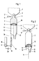
- the lock chamber 2 Under the pressurized container 1 of FIGS. 1 and 2 there is the lock chamber 2, which is connected to the container 1 via the outlet 3.
- the Container 1 can be, for example, a reactor in which there is constant overpressure.
- the closure body 4 belonging to the outlet 3 is opened, see FIG. 1, so that the solids can run through the outlet 3 into the lock chamber 2.
- the expansion valve 5 in line 6 is closed.
- the valve 5 is located at the upper end of the lock chamber.
- the lock chamber 2 has a displaceable base which consists of a ring 8 with seals 9 and a displaceable cover 10 sitting on the ring 8.
- a push rod 11 is connected to the cover.
- a plurality of guide rods 12, 13 are attached to the ring 8 and are slidably guided in the funnel-shaped wall part 2a of the lock chamber 2. Such a sliding guide is also available for the push rod 11 in the wall part 2a.
- Fig. 1 is shown schematically how the energy released when moving the lock chamber floor, which consists of the ring 8, the seals 9 and the cover 10, can be stored and at least partially recovered.
- the guide rod 12 cooperates with a hydraulic cylinder 16, the liquid of which is pressed through the line 17 into the pressure accumulator 18 when the ring 8 is moved downward.
- the pressure in the pressure accumulator 18 increases. If the ring 8 is to be moved upwards again towards the outlet 3, the pressure in the pressure accumulator 18 is returned to the hydraulic cylinder 16 via the line 19, in which a pump 20 is also located.
- the energy recovery is shown in a very simplified manner and it goes without saying in practice that all the guide rods 12, 13 would be provided with coupled hydraulic cylinders 16. In the drawing, however, such a representation has been omitted for the sake of clarity.
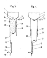
- the lock chamber 2a of FIGS. 3 and 4 has an up and down movable inner container 20 with a bottom valve 21, through which the solids after relaxation, cf. Fig. 4 flow away.
- the inner container 20 is in the filling position, cf. Fig. 3, directly below the off let 3a through which the solids leak down with the closure body 4 open.
- Seals 22 and 23 are arranged between the inner container 20 and the inner wall of the lock chamber 2a. Since the inner wall of the lock chamber 2a does not come into contact with solids in the area in which the seals move, the seals are protected during operation.
- the device for partially recovering the kinetic energy of the inner container 20 can be designed in the same way as in FIGS. 1 and 2 and is only partially shown in FIGS. 3 and 4. The explanations for FIGS. 1 and 2 apply analogously.
Landscapes
- Engineering & Computer Science (AREA)
- Mechanical Engineering (AREA)
- Filling Or Emptying Of Bunkers, Hoppers, And Tanks (AREA)
- Devices And Processes Conducted In The Presence Of Fluids And Solid Particles (AREA)
- Auxiliary Methods And Devices For Loading And Unloading (AREA)
- Air Transport Of Granular Materials (AREA)
Abstract
Der Behälter steht über einen verschließbaren Auslaß mit einer entleerbaren Schleusenkammer, die ein Entspannungsventil aufweist, in Verbindung. Um die Schleusenkammer zu entleeren, wird zunächst das dem Gas in der Schleusenkammr zur Verfügung stehende Volumen vergrößert, wobei sich der Druck in der Schleusenkammer verringert. Danach wird die Schleusenkammer geöffnet. 
Description
Die Erfindung betrifft ein Verfahren zum Austragen pulvriger oder körniger Feststoffe aus einem unter Überdruck stehenden Behälter, der über einen verschließbaren Auslaß mit einer entleerbaren Schleusenkammer in Verbindung steht, sowie eine Vorrichtung hierzu.The invention relates to a method for discharging powdery or granular solids from a pressurized container, which is connected via a closable outlet to an emptying lock chamber, and a device therefor.
Beim Ausschleusen feinkörniger oder pulverförmiger Schüttgüter aus unter Überdruck stehenden Behältern, z.B. Reaktoren, wird beim Entspannen der Schleusenkammer durch das ausströmende Entspannungsgas feines Material mitgerissen. Um dieses unerwünschte Austragen der Feststoffe zu verhindern, kann man beispielsweise die Schleusenkammer nur teilweise füllen, um so einen Beruhigungsraum oberhalb der Schüttung zum Abscheiden von aus der Schüttung mitgerissenen Feststoffen beim Entspannen zu schaffen. Eine andere Möglichkeit besteht darin, die Schleusenkammer sehr langsam zu entspannen, um die Strömungsgeschwindigkeit des Gases in der Kammer niedrig zu halten.When discharging fine-grained or powdery bulk goods from pressurized containers, e.g. Reactors, fine material is entrained by the escaping expansion gas when the lock chamber is released. In order to prevent this undesired discharge of the solids, the lock chamber, for example, can only be partially filled in order to create a calming space above the bed for separating solids entrained from the bed when relaxing. Another possibility is to relax the lock chamber very slowly in order to keep the flow rate of the gas in the chamber low.
Der Erfindung liegt die Aufgabe zugrunde, auch bei einer gefüllten Schleusenkammer zu vermeiden, daß beim Entspan nen der Kammer unerwünschte Mengen an Feststoffen mit dem Entspannungsgas ausgetragen werden.The invention has for its object to avoid even with a filled lock chamber that the expansion NEN unwanted amounts of solids are discharged into the chamber with the flash gas.
Erfindungsgemäß geschieht dies beim eingangs genannten Verfahren dadurch, daß man das dem Gas in der Schleusenkammer zur Verfügung stehende Volumen nach Einfüllen der Feststoffe und Verschließen des Behälter-Auslasses vergrößert, wobei sich der Druck in der Schleusenkammer verringert. Für die Volumenvergrößerung besteht technisch keine Grenze, so daß man auf diese Weise den Druck in der Schleusenkammer beliebig absenken kann, falls gewünscht, bis zu einem Restdruck von etwa 1 bar.According to the invention, this is done in the method mentioned at the outset by increasing the volume available to the gas in the lock chamber after filling in the solids and closing the container outlet, the pressure in the lock chamber decreasing. There is technically no limit to the volume increase, so that the pressure in the lock chamber can be reduced as desired, if desired, up to a residual pressure of about 1 bar.
Eine Ausgestaltungsmöglichkeit des Verfahrens besteht darin, daß man den Druck in der Schleusenkammer durch Vergrößern des dem Gas zur Verfügung stehenden Volumens bis auf einen restlichen Überdruck verringert und den restlichen Überdruck über ein Entspannungsventil beseitigt. Da nunmehr über das Entspannungsventil nicht mehr der gesamte Überdruck entspannt wird und die aus der Schüttung über das Ventil abzuführende Gasmenge verringert ist, kann man die Strömungsgeschwindigkeit des die Schüttung verlassenden Gases auf dem gewünscht niedrigen Wert halten. Auch steht durch die bereits erfolgte Volumenvergrößerung der Schleusenkammer ein Beruhigungsraum zur Verfügung, so daß mit dem Entspannungsgas mitgerissene Feststoffe noch in der Schleusenkammer wieder abgeschieden werden.One possible embodiment of the method is that the pressure in the lock chamber is reduced to a residual overpressure by increasing the volume available to the gas and the remaining overpressure is eliminated via an expansion valve. Now that the entire excess pressure is no longer released via the expansion valve and the amount of gas to be discharged from the bed via the valve is reduced, the flow rate of the gas leaving the bed can be kept at the desired low value. Due to the increase in volume of the lock chamber, a calming space is also available so that solids entrained with the expansion gas are still separated out in the lock chamber.
Die erfindungsgemäße Schleusenkammer zum Austragen pulvriger oder körniger Feststoffe aus einem unter Überdruck stehenden Behälter, der über einen verschließbaren Auslaß mit der Schleusenkammer in Verbindung steht, ist durch eine verschiebbare, abgedichtet geführte Kammerwand gekennzeichnet. Üblicherweise ist der Boden der Schleusen kammer verschiebbar ausgebildet. Zweckmäßigerweise besitzt der Boden der Schleusenkammer einen Auslauf mit einem verschiebbaren Deckel, durch welchen die Feststoffe nach der Entspannung die Schleusenkammer verlassen.The lock chamber according to the invention for discharging powdery or granular solids from a pressurized container which is connected to the lock chamber via a closable outlet is characterized by a displaceable, sealed guided chamber wall. Usually the bottom of the locks chamber designed slidably. The bottom of the lock chamber expediently has an outlet with a sliding cover, through which the solids leave the lock chamber after relaxation.
Eine Weiterbildung der Schleusenkammer besteht darin, daß die verschiebbare Wand bzw. der verschiebbare Boden mit einer Vorrichtung zur Rückgewinnung von Energie gekoppelt ist. Hierbei wird die Verschiebebewegung beim Entspannen der Schleuse benutzt, um außerhalb der Schleusenkammer Energie zu speichern, die dann zum Komprimieren der Gase in der Schleusenkammer wieder zur Verfügung steht. Für diese Energie-Rückgewinnung eignen sich besonders mechanische oder hydraulische Vorrichtungen.A further development of the lock chamber consists in the fact that the displaceable wall or the displaceable floor is coupled with a device for the recovery of energy. Here, the displacement movement is used when relaxing the lock to store energy outside the lock chamber, which is then available again for compressing the gases in the lock chamber. Mechanical or hydraulic devices are particularly suitable for this energy recovery.
Einzelheiten des Verfahrens und der Vorrichtung werden mit Hilfe der Zeichnung erläutert, in der in schematischer Darstellung jeweils ein Längsschnitt durch die Schleusenkammer zu sehen ist. Es zeigt:
- Fig. 1 eine erste Ausführungsform der Schleusenkammer in gefülltem Zustand,
- Fig. 2 die Schleusenkammer der Fig. 1 im entleerten Zustand,
- Fig. 3 eine zweite Ausführungsform der Schleusenkammer in gefülltem Zustand und
- Fig. 4 die Schleusenkammer der Fig. 3 nach der Entleerung.
- 1 shows a first embodiment of the lock chamber in the filled state,
- 2 the lock chamber of FIG. 1 in the emptied state,
- Fig. 3 shows a second embodiment of the lock chamber in the filled state and
- Fig. 4 shows the lock chamber of Fig. 3 after emptying.
Unter dem unter Überdruck stehenden Behälter 1 der Fig. 1 und 2 befindet sich die Schleusenkammer 2, die mit dem Behälter 1 über den Auslaß 3 in Verbindung steht. Beim Behälter 1 kann es sich z.B um einen Reaktor handeln, in welchem ständiger Überdruck herrscht. Zum Ausschleusen der im Behälter 1 befindlichen pulvrigen oder körnigen Feststoffe wird der zum Auslaß 3 gehörende Verschlußkörper 4 geöffnet, vergl. Fig. 1, so daß die Feststoffe durch den Auslaß 3 in die Schleusenkammer 2 laufen können. Dabei ist das Entspannungsventil 5 in der Leitung 6 geschlossen. Das Ventil 5 befindet sich am oberen Ende der Schleusenkammer.Under the pressurized
Die Schleusenkammer 2 besitzt einen verschiebbaren Boden, der aus einem Ring 8 mit Dichtungen 9 und einem auf dem Ring 8 sitzenden, verschiebbaren Deckel 10 besteht. Mit dem Deckel verbunden ist eine Schubstange 11. Am Ring 8 sind mehrere Führungsstangen 12,13 befestigt, die im trichterförmigen Wandteil 2a der Schleusenkammer 2 gleitend geführt sind. Eine solche Gleitführung ist auch für die Schubstange 11 im Wandteil 2a vorhanden.The
Wenn die Schleusenkammer 2 mit Feststoffen aus dem Behälter 1 gefüllt ist, vergl. Figur 1, wird der Auslaß 3 mit dem Verschlußkörper 4 verschlossen. In der Schleusenkammer 2 herrscht dann zunächst der gleiche Überdruck wie im Behälter 1. Nun wird der Ring 8 mit dem Deckel 10 nach unten bewegt und so das Volumen der Schleusenkammer 2 vergrößert. Dadurch reduziert sich der Druck in der Schleusenkammer 2 in der durch die Volumenverhältnisse vorgegebenen Weise. Hat der Ring 8 seine untere Endlage erreicht und beträgt der restliche Überdruck in der vergrößerten Schleusenkammer zwischen 0 und etwa 1 bar, so kann man durch Öffnen des Deckels 10, vergl. Fig. 2, eine geringe restliche Entspannung durch den Schleusenboden vornehmen. Die Feststoffe fließen dann am geöffneten Deckel 10 vorbei durch den Ring 8 nach unten aus der Schleusenkammer ab (Pfeil 15), wobei das Entspannungsventil 5 geschlossen bleiben kann.When the
Ist der restliche Überdruck bei nach unten ausgefahrenem Boden in der Schleusenkammer noch beträchtlich, so empfiehlt sich zunächst die Entspannung auf 1 bar durch das geöffnete Ventil 5. Diese Entspannung kann alternativ auch gleichzeitig mit der Bewegung des Bodens nach unten erfolgen.If the remaining overpressure in the lock chamber is still considerable when the floor is extended downwards, it is advisable to first relax to 1 bar through the
In Fig. 1 ist schematisch dargestellt, wie die beim Bewegen des Schleusenkammerbodens, der aus dem Ring 8, den Dichtungen 9 und dem Deckel 10 besteht, freigesetzte Energie gespeichert und mindestens teilweise wieder zurückgewonnen werden kann. Hierzu wirkt die Führungsstange 12 mit einem Hydraulikzylinder 16 zusammen, dessen Flüssigkeit beim Bewegen des Rings 8 nach unten durch die Leitung 17 in den Druckspeicher 18 gepreßt wird. Dabei erhöht sich der Druck im Druckspeicher 18. Will man den Ring 8 wieder nach oben zum Auslaß 3 hin bewegen, gibt man den Druck im Druckspeicher 18 über die Leitung 19, in welcher sich auch eine Pumpe 20 befindet, zurück in den Hydraulikzylinder 16. Die Energie-Rückgewinnung ist sehr vereinfacht dargestellt und es versteht sich für die Praxis von selbst, daß man sämtliche Führungsstangen 12,13 mit gekoppelten Hydraulikzylindern 16 versehen würde. In der Zeichnung wurde aber der besseren Übersichtigkeit wegen von einer derartigen Darstellung abgesehen.In Fig. 1 is shown schematically how the energy released when moving the lock chamber floor, which consists of the
Die Schleusenkammer 2a der Fig. 3 und 4 weist einen auf und ab bewegbaren Innenbehälter 20 mit Bodenventil 21 auf, durch das die Feststoffe nach der Entspannung, vgl. Fig. 4, abfließen. Der Innenbehälter 20 befindet sich in der Befüllungslage, vgl. Fig. 3, direkt unterhalb des Aus lasses 3a, durch den die Feststoffe bei geöffnetem Verschlußkörper 4 nach unten auslaufen. Zwischen dem Innenbehälter 20 und der Innenwand der Schleusenkammer 2a sind Dichtungen 22 und 23 angeordnet. Da die Innenwand der Schleusenkammer 2a in dem Bereich, in dem sich die Dichtungen bewegen, mit Feststoffen nicht in Kontakt kommt, werden die Dichtungen während des Betriebs geschont. Die Vorrichtung zum teilweisen Wiedergewinnen der Bewegungsenergie des Innenbehälters 20 kann genauso wie in Fig. 1 und 2 ausgebildet sein und ist in Fig. 3 und 4 nur zum Teil dargestellt. Die Erläuterungen zu den Fig. 1 und 2 gelten sinngemäß.The
Claims (6)
Applications Claiming Priority (2)
| Application Number | Priority Date | Filing Date | Title |
|---|---|---|---|
| DE19853526968 DE3526968A1 (en) | 1985-07-27 | 1985-07-27 | METHOD AND DEVICE FOR DISCHARGING SOLIDS FROM A CONTAINER UNDER RBERPRESSURE |
| DE3526968 | 1985-07-27 |
Publications (2)
| Publication Number | Publication Date |
|---|---|
| EP0210673A1 true EP0210673A1 (en) | 1987-02-04 |
| EP0210673B1 EP0210673B1 (en) | 1989-04-19 |
Family
ID=6276972
Family Applications (1)
| Application Number | Title | Priority Date | Filing Date |
|---|---|---|---|
| EP86200999A Expired EP0210673B1 (en) | 1985-07-27 | 1986-06-10 | Air lock device for removing solid materials from a pressure vessel |
Country Status (6)
| Country | Link |
|---|---|
| US (1) | US4753565A (en) |
| EP (1) | EP0210673B1 (en) |
| JP (1) | JPS6227227A (en) |
| AU (1) | AU581331B2 (en) |
| DE (2) | DE3526968A1 (en) |
| ZA (1) | ZA865570B (en) |
Families Citing this family (4)
| Publication number | Priority date | Publication date | Assignee | Title |
|---|---|---|---|---|
| DE3911752C1 (en) * | 1989-04-11 | 1990-06-21 | Metallgesellschaft Ag, 6000 Frankfurt, De | |
| DE19633674C2 (en) | 1996-08-21 | 1998-07-16 | Hamburger Gaswerke Gmbh | In-line gas preheating |
| US6220791B1 (en) * | 1999-03-11 | 2001-04-24 | Board Of Trustees Of The University Of Arkansas | Apparatus and method for the aerosolization of powders |
| GB201610848D0 (en) * | 2016-06-21 | 2016-08-03 | Syngas Products Ltd | A system for pyrolysing material |
Citations (4)
| Publication number | Priority date | Publication date | Assignee | Title |
|---|---|---|---|---|
| CH470307A (en) * | 1965-07-06 | 1969-03-31 | Nat Eng Co | Pneumatic conveyor |
| DE1911485A1 (en) * | 1968-03-06 | 1969-10-09 | Mitsuzo Ogino | vice |
| DE2353288A1 (en) * | 1972-10-27 | 1974-05-09 | Metodgolv Ab | METHOD AND DEVICE FOR TRANSPORTING BULK GOODS |
| DE2625263A1 (en) * | 1976-06-04 | 1977-12-08 | Waeschle Maschf Gmbh | DEVICE FOR INPUTING BULK MATERIAL INTO A PNEUMATIC CONVEYOR LINE |
Family Cites Families (8)
| Publication number | Priority date | Publication date | Assignee | Title |
|---|---|---|---|---|
| US2151514A (en) * | 1934-03-17 | 1939-03-21 | Kali Forschungsanstalt Gmbh | Method of and apparatus for conveying material containing at least one expansible constituent |
| US2667280A (en) * | 1949-04-01 | 1954-01-26 | Standard Oil Dev Co | Handling finely divided solid materials |
| US3001652A (en) * | 1958-10-24 | 1961-09-26 | Fossil Fuels Inc | Apparatus for feeding finely divided solids |
| BE633729A (en) * | 1962-08-10 | |||
| FR2287277A1 (en) * | 1974-10-09 | 1976-05-07 | Air Ind | POWDER FEEDING DEVICE |
| US4273156A (en) * | 1980-03-28 | 1981-06-16 | Borodin Alexandr A | Shutoff device |
| US4398852A (en) * | 1980-04-21 | 1983-08-16 | Hri, Inc. | Process and apparatus for adding and removing particles from pressurized reactors |
| US4400125A (en) * | 1981-06-12 | 1983-08-23 | Chevron Research Company | Method of and apparatus for charging ground hydrocarbonaceous material to a pressurized gasification system |
-
1985
- 1985-07-27 DE DE19853526968 patent/DE3526968A1/en not_active Withdrawn
-
1986
- 1986-06-10 DE DE8686200999T patent/DE3662865D1/en not_active Expired
- 1986-06-10 EP EP86200999A patent/EP0210673B1/en not_active Expired
- 1986-07-01 JP JP61154923A patent/JPS6227227A/en active Pending
- 1986-07-07 US US06/882,277 patent/US4753565A/en not_active Expired - Fee Related
- 1986-07-25 AU AU60563/86A patent/AU581331B2/en not_active Ceased
- 1986-07-25 ZA ZA865570A patent/ZA865570B/en unknown
Patent Citations (4)
| Publication number | Priority date | Publication date | Assignee | Title |
|---|---|---|---|---|
| CH470307A (en) * | 1965-07-06 | 1969-03-31 | Nat Eng Co | Pneumatic conveyor |
| DE1911485A1 (en) * | 1968-03-06 | 1969-10-09 | Mitsuzo Ogino | vice |
| DE2353288A1 (en) * | 1972-10-27 | 1974-05-09 | Metodgolv Ab | METHOD AND DEVICE FOR TRANSPORTING BULK GOODS |
| DE2625263A1 (en) * | 1976-06-04 | 1977-12-08 | Waeschle Maschf Gmbh | DEVICE FOR INPUTING BULK MATERIAL INTO A PNEUMATIC CONVEYOR LINE |
Also Published As
| Publication number | Publication date |
|---|---|
| AU581331B2 (en) | 1989-02-16 |
| ZA865570B (en) | 1988-03-30 |
| EP0210673B1 (en) | 1989-04-19 |
| JPS6227227A (en) | 1987-02-05 |
| AU6056386A (en) | 1987-01-29 |
| DE3662865D1 (en) | 1989-05-24 |
| US4753565A (en) | 1988-06-28 |
| DE3526968A1 (en) | 1987-01-29 |
Similar Documents
| Publication | Publication Date | Title |
|---|---|---|
| DE3926591A1 (en) | DEVICE FOR FILLING CONTAINERS | |
| DE2604383C2 (en) | Device for introducing granular material into a pressure reactor | |
| EP0210673A1 (en) | Air lock device for removing solid materials from a pressure vessel | |
| DE2556162C2 (en) | Device and method for introducing fine-grained to pulverulent fuels into a gasification device under increased pressure | |
| DD140756A6 (en) | SOLID PUMP AND METHOD FOR GASIFICATION OF FINE-CORNIC TO DUST-FUEL FUELS | |
| DE2444377B2 (en) | METHOD AND DEVICE FOR MANUFACTURING MOLDED PARTS FOR FOUNDRY | |
| DE4010638C2 (en) | ||
| EP0167052B1 (en) | Device for feeding a kiln, in particular a rotary drum furnace, with materials to be burned, in particular refuse | |
| DE3616990C1 (en) | Air blast device for resolving material build-up in storage silos for bulk material | |
| DE1767453A1 (en) | Method and device for the pneumatic injection of solid particles into a high pressure zone | |
| EP0903440B1 (en) | Method and device for ground improvement with a powder binder | |
| DE3340007C2 (en) | ||
| DE3502999A1 (en) | Apparatus for emptying the residue from a tank for containing liquid | |
| DE2537817A1 (en) | DEVICE FOR CAPTURING GASES EMISSED WHEN FILLING A TANK | |
| DE483728C (en) | Weight machine | |
| DE157971C (en) | ||
| DE895083C (en) | Device for feeding a pressure lubrication system | |
| DE1432386A1 (en) | Method and device for the even filling of bottles | |
| DE1237948B (en) | Procedures for storing and disposing of garbage | |
| DE1531769C (en) | Garbage storage device on garbage trucks or trailers | |
| DE565130C (en) | Pan mill with bunkers and measuring vessels | |
| CH629720A5 (en) | Method for gassing a receiving and dispensing container for liquids and pastes under pressure and internal container for carrying out this method | |
| DE3813899A1 (en) | Conveying device for solids into or out of process spaces at different pressures | |
| DE3921762A1 (en) | Contaminated bulk material transfer - in barrels by hopper and measurement containers | |
| DE1049830B (en) | Central lock for pressure vessel lid |
Legal Events
| Date | Code | Title | Description |
|---|---|---|---|
| PUAI | Public reference made under article 153(3) epc to a published international application that has entered the european phase |
Free format text: ORIGINAL CODE: 0009012 |
|
| AK | Designated contracting states |
Kind code of ref document: A1 Designated state(s): AT BE DE FR GB IT NL SE |
|
| 17P | Request for examination filed |
Effective date: 19870505 |
|
| 17Q | First examination report despatched |
Effective date: 19880208 |
|
| GRAA | (expected) grant |
Free format text: ORIGINAL CODE: 0009210 |
|
| AK | Designated contracting states |
Kind code of ref document: B1 Designated state(s): BE DE FR GB IT NL |
|
| PGFP | Annual fee paid to national office [announced via postgrant information from national office to epo] |
Ref country code: FR Payment date: 19890421 Year of fee payment: 4 |
|
| REF | Corresponds to: |
Ref document number: 3662865 Country of ref document: DE Date of ref document: 19890524 |
|
| PGFP | Annual fee paid to national office [announced via postgrant information from national office to epo] |
Ref country code: BE Payment date: 19890612 Year of fee payment: 4 |
|
| ET | Fr: translation filed | ||
| PGFP | Annual fee paid to national office [announced via postgrant information from national office to epo] |
Ref country code: NL Payment date: 19890630 Year of fee payment: 4 |
|
| ITF | It: translation for a ep patent filed |
Owner name: STUDIO JAUMANN |
|
| GBT | Gb: translation of ep patent filed (gb section 77(6)(a)/1977) | ||
| PLBE | No opposition filed within time limit |
Free format text: ORIGINAL CODE: 0009261 |
|
| STAA | Information on the status of an ep patent application or granted ep patent |
Free format text: STATUS: NO OPPOSITION FILED WITHIN TIME LIMIT |
|
| 26N | No opposition filed | ||
| PG25 | Lapsed in a contracting state [announced via postgrant information from national office to epo] |
Ref country code: GB Effective date: 19900610 |
|
| ITTA | It: last paid annual fee | ||
| PG25 | Lapsed in a contracting state [announced via postgrant information from national office to epo] |
Ref country code: BE Effective date: 19900630 |
|
| BERE | Be: lapsed |
Owner name: METALLGESELLSCHAFT A.G. Effective date: 19900630 |
|
| PG25 | Lapsed in a contracting state [announced via postgrant information from national office to epo] |
Ref country code: NL Effective date: 19910101 |
|
| GBPC | Gb: european patent ceased through non-payment of renewal fee | ||
| NLV4 | Nl: lapsed or anulled due to non-payment of the annual fee | ||
| PG25 | Lapsed in a contracting state [announced via postgrant information from national office to epo] |
Ref country code: FR Effective date: 19910228 |
|
| REG | Reference to a national code |
Ref country code: FR Ref legal event code: ST |
|
| PGFP | Annual fee paid to national office [announced via postgrant information from national office to epo] |
Ref country code: DE Payment date: 19930708 Year of fee payment: 8 |
|
| PG25 | Lapsed in a contracting state [announced via postgrant information from national office to epo] |
Ref country code: DE Effective date: 19950301 |
|
| PG25 | Lapsed in a contracting state [announced via postgrant information from national office to epo] |
Ref country code: IT Free format text: LAPSE BECAUSE OF NON-PAYMENT OF DUE FEES;WARNING: LAPSES OF ITALIAN PATENTS WITH EFFECTIVE DATE BEFORE 2007 MAY HAVE OCCURRED AT ANY TIME BEFORE 2007. THE CORRECT EFFECTIVE DATE MAY BE DIFFERENT FROM THE ONE RECORDED. Effective date: 20050610 |