EP0210404B1 - Transmission train for motor vehicles - Google Patents
Transmission train for motor vehicles Download PDFInfo
- Publication number
- EP0210404B1 EP0210404B1 EP86108244A EP86108244A EP0210404B1 EP 0210404 B1 EP0210404 B1 EP 0210404B1 EP 86108244 A EP86108244 A EP 86108244A EP 86108244 A EP86108244 A EP 86108244A EP 0210404 B1 EP0210404 B1 EP 0210404B1
- Authority
- EP
- European Patent Office
- Prior art keywords
- electronic
- unit
- gearbox
- regulating
- engine
- Prior art date
- Legal status (The legal status is an assumption and is not a legal conclusion. Google has not performed a legal analysis and makes no representation as to the accuracy of the status listed.)
- Expired
Links
- 230000005540 biological transmission Effects 0.000 title description 43
- 230000001105 regulatory effect Effects 0.000 claims description 22
- 238000002485 combustion reaction Methods 0.000 claims description 20
- 239000000446 fuel Substances 0.000 claims description 18
- 230000008859 change Effects 0.000 claims description 12
- 230000006870 function Effects 0.000 claims description 11
- 238000012545 processing Methods 0.000 claims description 6
- 238000002347 injection Methods 0.000 claims description 5
- 239000007924 injection Substances 0.000 claims description 5
- 230000003111 delayed effect Effects 0.000 claims 1
- 238000002360 preparation method Methods 0.000 claims 1
- 230000001276 controlling effect Effects 0.000 description 5
- 238000012937 correction Methods 0.000 description 5
- 238000010586 diagram Methods 0.000 description 5
- 238000000034 method Methods 0.000 description 4
- 238000005457 optimization Methods 0.000 description 4
- 239000000243 solution Substances 0.000 description 4
- 230000001133 acceleration Effects 0.000 description 3
- 230000000694 effects Effects 0.000 description 3
- 238000004146 energy storage Methods 0.000 description 3
- 238000005259 measurement Methods 0.000 description 3
- 230000008569 process Effects 0.000 description 3
- 238000013461 design Methods 0.000 description 2
- 230000007613 environmental effect Effects 0.000 description 2
- 239000003921 oil Substances 0.000 description 2
- 238000003860 storage Methods 0.000 description 2
- 241000237536 Mytilus edulis Species 0.000 description 1
- 230000009471 action Effects 0.000 description 1
- 230000006978 adaptation Effects 0.000 description 1
- 230000000712 assembly Effects 0.000 description 1
- 238000000429 assembly Methods 0.000 description 1
- 230000006399 behavior Effects 0.000 description 1
- 230000008901 benefit Effects 0.000 description 1
- 230000000903 blocking effect Effects 0.000 description 1
- 230000003750 conditioning effect Effects 0.000 description 1
- 238000006073 displacement reaction Methods 0.000 description 1
- 238000005516 engineering process Methods 0.000 description 1
- 238000003912 environmental pollution Methods 0.000 description 1
- 230000002349 favourable effect Effects 0.000 description 1
- 230000002706 hydrostatic effect Effects 0.000 description 1
- 230000006872 improvement Effects 0.000 description 1
- 230000003993 interaction Effects 0.000 description 1
- 238000004519 manufacturing process Methods 0.000 description 1
- 230000004048 modification Effects 0.000 description 1
- 238000012986 modification Methods 0.000 description 1
- 239000010705 motor oil Substances 0.000 description 1
- 235000020638 mussel Nutrition 0.000 description 1
- 230000000630 rising effect Effects 0.000 description 1
Images

Classifications
-
- B—PERFORMING OPERATIONS; TRANSPORTING
- B60—VEHICLES IN GENERAL
- B60W—CONJOINT CONTROL OF VEHICLE SUB-UNITS OF DIFFERENT TYPE OR DIFFERENT FUNCTION; CONTROL SYSTEMS SPECIALLY ADAPTED FOR HYBRID VEHICLES; ROAD VEHICLE DRIVE CONTROL SYSTEMS FOR PURPOSES NOT RELATED TO THE CONTROL OF A PARTICULAR SUB-UNIT
- B60W10/00—Conjoint control of vehicle sub-units of different type or different function
- B60W10/04—Conjoint control of vehicle sub-units of different type or different function including control of propulsion units
- B60W10/06—Conjoint control of vehicle sub-units of different type or different function including control of propulsion units including control of combustion engines
-
- B—PERFORMING OPERATIONS; TRANSPORTING
- B60—VEHICLES IN GENERAL
- B60K—ARRANGEMENT OR MOUNTING OF PROPULSION UNITS OR OF TRANSMISSIONS IN VEHICLES; ARRANGEMENT OR MOUNTING OF PLURAL DIVERSE PRIME-MOVERS IN VEHICLES; AUXILIARY DRIVES FOR VEHICLES; INSTRUMENTATION OR DASHBOARDS FOR VEHICLES; ARRANGEMENTS IN CONNECTION WITH COOLING, AIR INTAKE, GAS EXHAUST OR FUEL SUPPLY OF PROPULSION UNITS IN VEHICLES
- B60K31/00—Vehicle fittings, acting on a single sub-unit only, for automatically controlling vehicle speed, i.e. preventing speed from exceeding an arbitrarily established velocity or maintaining speed at a particular velocity, as selected by the vehicle operator
- B60K31/02—Vehicle fittings, acting on a single sub-unit only, for automatically controlling vehicle speed, i.e. preventing speed from exceeding an arbitrarily established velocity or maintaining speed at a particular velocity, as selected by the vehicle operator including electrically actuated servomechanism including an electric control system or a servomechanism in which the vehicle velocity affecting element is actuated electrically
-
- B—PERFORMING OPERATIONS; TRANSPORTING
- B60—VEHICLES IN GENERAL
- B60W—CONJOINT CONTROL OF VEHICLE SUB-UNITS OF DIFFERENT TYPE OR DIFFERENT FUNCTION; CONTROL SYSTEMS SPECIALLY ADAPTED FOR HYBRID VEHICLES; ROAD VEHICLE DRIVE CONTROL SYSTEMS FOR PURPOSES NOT RELATED TO THE CONTROL OF A PARTICULAR SUB-UNIT
- B60W10/00—Conjoint control of vehicle sub-units of different type or different function
- B60W10/04—Conjoint control of vehicle sub-units of different type or different function including control of propulsion units
-
- B—PERFORMING OPERATIONS; TRANSPORTING
- B60—VEHICLES IN GENERAL
- B60W—CONJOINT CONTROL OF VEHICLE SUB-UNITS OF DIFFERENT TYPE OR DIFFERENT FUNCTION; CONTROL SYSTEMS SPECIALLY ADAPTED FOR HYBRID VEHICLES; ROAD VEHICLE DRIVE CONTROL SYSTEMS FOR PURPOSES NOT RELATED TO THE CONTROL OF A PARTICULAR SUB-UNIT
- B60W10/00—Conjoint control of vehicle sub-units of different type or different function
- B60W10/10—Conjoint control of vehicle sub-units of different type or different function including control of change-speed gearings
- B60W10/101—Infinitely variable gearings
- B60W10/103—Infinitely variable gearings of fluid type
-
- B—PERFORMING OPERATIONS; TRANSPORTING
- B60—VEHICLES IN GENERAL
- B60W—CONJOINT CONTROL OF VEHICLE SUB-UNITS OF DIFFERENT TYPE OR DIFFERENT FUNCTION; CONTROL SYSTEMS SPECIALLY ADAPTED FOR HYBRID VEHICLES; ROAD VEHICLE DRIVE CONTROL SYSTEMS FOR PURPOSES NOT RELATED TO THE CONTROL OF A PARTICULAR SUB-UNIT
- B60W10/00—Conjoint control of vehicle sub-units of different type or different function
- B60W10/10—Conjoint control of vehicle sub-units of different type or different function including control of change-speed gearings
- B60W10/11—Stepped gearings
-
- B—PERFORMING OPERATIONS; TRANSPORTING
- B60—VEHICLES IN GENERAL
- B60W—CONJOINT CONTROL OF VEHICLE SUB-UNITS OF DIFFERENT TYPE OR DIFFERENT FUNCTION; CONTROL SYSTEMS SPECIALLY ADAPTED FOR HYBRID VEHICLES; ROAD VEHICLE DRIVE CONTROL SYSTEMS FOR PURPOSES NOT RELATED TO THE CONTROL OF A PARTICULAR SUB-UNIT
- B60W30/00—Purposes of road vehicle drive control systems not related to the control of a particular sub-unit, e.g. of systems using conjoint control of vehicle sub-units
- B60W30/18—Propelling the vehicle
- B60W30/188—Controlling power parameters of the driveline, e.g. determining the required power
- B60W30/1882—Controlling power parameters of the driveline, e.g. determining the required power characterised by the working point of the engine, e.g. by using engine output chart
-
- B—PERFORMING OPERATIONS; TRANSPORTING
- B60—VEHICLES IN GENERAL
- B60W—CONJOINT CONTROL OF VEHICLE SUB-UNITS OF DIFFERENT TYPE OR DIFFERENT FUNCTION; CONTROL SYSTEMS SPECIALLY ADAPTED FOR HYBRID VEHICLES; ROAD VEHICLE DRIVE CONTROL SYSTEMS FOR PURPOSES NOT RELATED TO THE CONTROL OF A PARTICULAR SUB-UNIT
- B60W2710/00—Output or target parameters relating to a particular sub-units
- B60W2710/06—Combustion engines, Gas turbines
- B60W2710/0616—Position of fuel or air injector
-
- B—PERFORMING OPERATIONS; TRANSPORTING
- B60—VEHICLES IN GENERAL
- B60W—CONJOINT CONTROL OF VEHICLE SUB-UNITS OF DIFFERENT TYPE OR DIFFERENT FUNCTION; CONTROL SYSTEMS SPECIALLY ADAPTED FOR HYBRID VEHICLES; ROAD VEHICLE DRIVE CONTROL SYSTEMS FOR PURPOSES NOT RELATED TO THE CONTROL OF A PARTICULAR SUB-UNIT
- B60W2710/00—Output or target parameters relating to a particular sub-units
- B60W2710/10—Change speed gearings
- B60W2710/1005—Transmission ratio engaged
-
- F—MECHANICAL ENGINEERING; LIGHTING; HEATING; WEAPONS; BLASTING
- F16—ENGINEERING ELEMENTS AND UNITS; GENERAL MEASURES FOR PRODUCING AND MAINTAINING EFFECTIVE FUNCTIONING OF MACHINES OR INSTALLATIONS; THERMAL INSULATION IN GENERAL
- F16H—GEARING
- F16H61/00—Control functions within control units of change-speed- or reversing-gearings for conveying rotary motion ; Control of exclusively fluid gearing, friction gearing, gearings with endless flexible members or other particular types of gearing
- F16H2061/0015—Transmission control for optimising fuel consumptions
-
- F—MECHANICAL ENGINEERING; LIGHTING; HEATING; WEAPONS; BLASTING
- F16—ENGINEERING ELEMENTS AND UNITS; GENERAL MEASURES FOR PRODUCING AND MAINTAINING EFFECTIVE FUNCTIONING OF MACHINES OR INSTALLATIONS; THERMAL INSULATION IN GENERAL
- F16H—GEARING
- F16H61/00—Control functions within control units of change-speed- or reversing-gearings for conveying rotary motion ; Control of exclusively fluid gearing, friction gearing, gearings with endless flexible members or other particular types of gearing
- F16H2061/0018—Transmission control for optimising exhaust emissions
-
- F—MECHANICAL ENGINEERING; LIGHTING; HEATING; WEAPONS; BLASTING
- F16—ENGINEERING ELEMENTS AND UNITS; GENERAL MEASURES FOR PRODUCING AND MAINTAINING EFFECTIVE FUNCTIONING OF MACHINES OR INSTALLATIONS; THERMAL INSULATION IN GENERAL
- F16H—GEARING
- F16H2306/00—Shifting
- F16H2306/40—Shifting activities
- F16H2306/48—Synchronising of new gear
Definitions
- the invention relates to a regulating and control system for a motor vehicle drive train with features according to the preamble of claim 1.
- the invention is based on a regulating and control system known from DE-A-2 811 574.
- the internal combustion engine is assigned its own motor electronics to regulate its output, and the gearbox is adapted to have its own gearbox electronics for its adapted switching.
- the positions of the accelerator pedal and gear selector which transmit the driver's wish to the electronics are not passed on directly to the internal combustion engine or the transmission, but are first fed to the electronics, processed there and only then passed on as corresponding setpoint signals.
- the electronics mentioned it is possible to vary the (proportional in conventional systems) influence of the operating elements on the actuators, for example the accelerator pedal on the throttle valve of the carburetor or the control rod of an injection pump, outside the proportionality.
- additional electronics are thus connected between the operating elements, such as the accelerator pedal, brake pedal, gear selector, and the unit-specific electronics, such as engine electronics, transmission electronics and the like, whereby the limits of operational optimization compared to the previously electronically controlled vehicle drive trains are noticeable can be expanded.
- the optimization of the regulation and control of the drive train can thus take place simultaneously taking into account the economy, the efficiency and the environmental impact, by the appropriate design and programming of the control units (engine electronics, transmission electronics and similar electronics) and the functionally higher-level electronics (host computer) Drivetrain can be controlled coordinated.
- the invention is based on the finding that the characteristics and / or the operation of a component of a drive train can be influenced or changed by another component, and by external influences (weight, temperature, terrain, etc.), and that by taking these factors into account Optimization of the regulation and control of a drive train is extensible. For example, it was previously not possible to control the internal combustion engine and the transmission depending on the operating state of the drive train and at the same time on the outside environment.
- the external environment is, for example, the terrain (driving uphill, driving on the motorway, loading the vehicle, etc.).
- the third electronics functionally superior to the engine electronics and transmission electronics is referred to only as the master computer.
- the master computer now offers the possibility of processing the driver's requests transmitted via the operating elements (accelerator pedal, brake pedal, gear selector and the like) in such a way that an adjustment of the corresponding drive train-side actuators does not follow the operating elements more or less directly, but in such a way that it does so
- An economical and comfortable operation of the drive train or the vehicle is given which takes wear and the environment into account.
- An uncontrolled operation of the pedals does not result in an uncontrolled driving style (if the steering is disregarded). The effect of a so-called "lead foot” does not appear.
- a speed post function can also be included, including the engine and transmission controls. So that Adherence to the target speed can also be carried out on a hill or downhill by automatically changing gears at the given time. Due to the simultaneous and coordinated control of the engine and transmission, it is also possible to take into account a changed torque ratio in the transmission when changing gears by adapting the engine torque in such a way that a tensile force compensation takes place. The coordinated control also avoids unnecessary shifts (upshifts).
- self-sufficient engine electronics and transmission electronics ensures the functionality of the vehicle in the event of a failure of the host computer, to which they are only functionally subordinate to the extent that they only receive setpoints from the host computer. If a setpoint to be calculated by the host computer fails, the control element signal is sent directly to it as a setpoint.
- the electronics and the host computer are preferably separate components; this enables a good adaptation to different drive systems by combining the individual components according to the respective application. It is therefore not necessary to change all control units (electronics) and drive train elements for each concept.
- the master computer essentially consists of at least one signal processing unit, input / output units as well as storage units and a microprocessor.
- the input signals from the operating elements are processed and fed to the input unit of the host computer.
- At least some of the processed signals are also simultaneously supplied to the electronics (electronic controller).
- the host computer receives the signals of the accelerator pedal positions, as well as actual values such as fuel supply position, transmission status, brake pressure and the like, as well as further measured values, such as engine torque, transmission drive speed, the pump settings and pressure of a hydraulic transmission and, if applicable, the load, engine temperature, exhaust gas values, etc. and changes these signals, referred to globally as measured values.
- the characteristic curves of the respective internal combustion engine as well as the transmission and the brake system are also stored in the master computer.
- a program is entered into the master computer, which is used to calculate setpoint signals for the engine electronics and transmission electronics using the measured values, the stored drive-specific values and an optimization criterion.
- centrally calculated target values can thus be matched to the entire drive train and the vehicle, so that not only the engine-specific data and the command variables specified by the driver via the accelerator pedal, but also the data from other drive train components and from the control unit for controlling the fuel supply to the internal combustion engine Outdoor environment should be considered. This data can then be used for coordinated influencing of all components of the drive train, so that a control of the drive unit that optimizes all these factors is possible between efficiency, wear and tear, environmental protection and driving comfort.
- the master computer is designed in such a way that it stores measured values from the past and processes them to determine the current operating mode of the vehicle. Due to the previous driving style, e.g. largely constant speed, which suggests a trip on a freeway, or heavily interrupted trips, which can be traced back to a trip within a city, the current operating mode can be determined with appropriate programming of the host computer and included in the determination of the target values.
- the software and thus the entire control unit group can be adjusted to different vehicle regulations, namely, cars or buses, garbage trucks or trucks, by means of only software changes.
- Sensors provided in the drive train record the current state of the elements of the drive train or the vehicle.
- the actual value signals can preferably be fed to the corresponding electronic parts, from where they are passed on to the master computer.
- This has the advantage that already existing components (engine plus engine electronics, transmission plus transmission electronics) can be integrated unchanged into the drive system according to the invention.
- the position of the control lever for the fuel injection quantity is supplied to the engine electronics as the actual injection quantity value.
- the actual value is compared with a target value specified by the host computer and the control signal is generated from it, which acts on the corresponding actuator.
- the drive system according to the invention can be expanded in that one or more additional electronics, such as, for example, electronics for regulating an energy store or the braking system, can be controlled via the master computer. In this way, these functions can also be controlled in a coordinated manner with the others.
- additional electronics such as, for example, electronics for regulating an energy store or the braking system
- the brake pedal it will be expedient for the brake pedal to interact mechanically / hydraulically with the brakes in the usual manner and at the same time to generate a signal for the master computer, which, in cooperation with the brake electronics, acts on the braking process in order to influence it favorably, for example blocking to avoid the brakes.
- a braking system can also optimize the braking process while maintaining a safe braking activity.
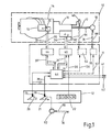
- the drive system shown in Fig. 1 consists of a drive train 10, further assigned to the components of the drive train, in the dash-dotted box 11 summarized control units and combined in box 12 controls that act on the control units.
- An internal combustion engine 14 with an associated fuel supply system 15, a transmission 16 with an associated output axle 17, and the drive wheel axle 18, a braking energy store 40 and the braking system 52 form the drive train 10.
- the driver uses, as usual, an accelerator pedal 20, a brake pedal 21 and a shift lever 22.
- the pedal travel or angle ag, a b is measured in each case by a travel sensor 26 or 27, which output the corresponding signals 28, 29 .
- the shift lever 22 indicates the respectively desired operating mode (forward, reverse travel V, R, idle N or level, rising, falling Fart 1, 2, 3) via corresponding signals 30.
- the signals 27, 29, 30 represent the driver's desire to drive.
- sensors, not shown in greater detail, assigned to the energy store 40 and the brake system 52 are provided, which deliver corresponding actual signals 33 to 36.
- Sensors 41, 42 provide further measured values or vehicle data, such as Acceleration, oil pressure, engine temperature, exhaust gas, vehicle weight, etc.
- control units drawn within the border 11 consist of motor electronics 44 for regulating the fuel supply for the internal combustion engine 14, transmission electronics 45 for regulating the transmission ratio of the transmission 16, and a master computer 46 functionally superordinate to the two electronics parts 44 and 45, which consists of the
- the aforementioned measured values 27, 29, 41, 42, 33, 34 or 33 'and 34' are used to calculate target values 50 and 51 for the motor electronics 44 or gear electronics 45.
- the accelerator pedal 20 acts exclusively on the master computer 46 in the case of FIG. 1, while the brake pedal 21 actuates the brakes 52 in the usual manner and additionally outputs the signal 29 to the master computer 46.
- the signals 30 of the gear switch 22 are input directly to the transmission electronics 45. However, it is also possible to feed this signal 30 and the brake pedal signal 29 directly to the host computer 46.
- control units can easily be expanded by additional electronics 54, 55, which also receive target signals 56, 57 from the host computer 46 and are used to control further functional units or elements of the drive train 10.
- additional electronics 54, 55 which also receive target signals 56, 57 from the host computer 46 and are used to control further functional units or elements of the drive train 10.
- the energy store 40 can be controlled with the additional electronics 54 and the braking system can be controlled with the second additional electronics 55.
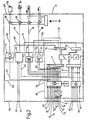
- control unit 2 shows a block diagram of the control units (electronics 44, 45, 46, 54, 55) integrated in a structural unit 11, which on the left with an interface 58 for the input signals, ie the measurement signals, and on the right with an interface 59 for the output signals that control the powertrain are limited.
- control devices electronics 44, 45, 46, 54, 55
- the motor electronics 44 and the transmission electronics 45 and any further electronics 54, 55 and the host computer 46 are to be designed and manufactured separately from one another and are only connected in the vehicle by signal supply lines.
- the master computer 46 (FIG. 2) consists of a signal processor 60 for the measured values, a microprocessor 73, a memory 74 and input-output units 71, 72, 75 and 76.
- the additional electronics 54 and 55 and the motor electronics 44, the transmission electronics 45 and associated power units 80 for controlling the actuators are integrated.
- the characteristic curves (functions of the power, the torque and the fuel consumption as a function of the engine speed) of the internal combustion engine 14, the characteristic curve for the optimal operation of the transmission 16, and the characteristic diagrams of any drive operating components are stored in the memory 74.
- the measurement data and output data of the host computer 46 are also stored over a predetermined, immediately past period.
- the driver's request regarding the driving speed is initiated by the accelerator pedal position ag and consequently the corresponding signal 27 in the signal processing 60.
- the signal 27 measured by the displacement sensor 26 is processed in the signal conditioning 60 according to a method known in control engineering and converted in an analog / digital converter 71 for a signal that can be processed in the microprocessor 73.
- the processed signal 27 ' is simultaneously fed directly to the engine electronics 44 as a setpoint specification, while the microprocessor 73 uses this signal 27', the actual value 33 and other measurement signals, namely engine speed n m , engine oil temperature t oil , gear position ap, output speed n a of the transmission 16, outside temperature, exhaust gas properties, any energy storage data, and stored data, such as the drive characteristics, a setpoint correction signal 50 'is determined.
- the setpoint correction signal 50 ' the setpoint 27' specified and processed by the accelerator pedal 20 is modified with a view to optimum operation not only of the internal combustion engine 14, but of the entire drive train 10.
- the modified, ie optimized, setpoint value 50 ′ for the adjustment angle of the fuel supply actuator 25 is measured and processed in the engine electronics 44
- the instantaneous actual value 33 ' is compared, which corresponds to the instantaneous adjustment angle of the fuel supply actuator 25.
- the comparison signal namely the control signal 90 for the fuel supply
- the actuator 25 of the fuel supply system 15 is finally actuated via an amplifier 81 of the power electronics 80.
- the actual signal 33 of the fuel supply system 15, contrary to the example according to FIG. 1, is fed directly to the host computer 46, in which the actual signal 33 is processed with the signal processing 60 provided in the host computer 46 and sent to the microprocessor 73 and the engine electronics 44 can be passed on, which ensures the emergency function in the event of failure of the host computer 46.
- the correction signal 50 ' is not generated. In such a case, there is no need to correct the predetermined target value 27 ′, which is therefore compared to the actual signal 33 ′ for generating the control signal 90 without modification in the motor electronics 44.
- the internal combustion engine 14 is therefore continued to be operated in a conventional manner.
- the internal combustion engine control can also be carried out in such a way that the setpoint correction is carried out in the master computer 46 and that the motor electronics 44 directly receive the optimized setpoint signal 50, as is provided in the example according to FIG. 1. In the event of a failure of the master computer 46, the uncorrected, predetermined target value 27, 27 'is then transmitted.
- the host computer 46 uses the current state 34 (ap) (actual value) of the hydrostats 91 (FIG. 2), for example a hydrostatic transmission 16, the accelerator pedal signal 27, the characteristic maps of the internal combustion engine 14 and the transmission 16, of the current transmission ratio , the engine speed n m , the vehicle load, any energy storage data, the preselected operating mode V, N, R, 1 ... using the gear switch 22 calculates a target value 51 which represents the optimal gear of the transmission 16 for the current operating state of the vehicle. From this setpoint 51 and the prepared actual value 34 'and taking into account the selected operating mode 30, the corresponding gear is engaged by the transmission electronics 45.
- the information is exchanged between the internal combustion engine 14 and the transmission 16 via the control computer 46, so that the other component is also taken into account when controlling one component.
- any other factors that affect the operation can be taken into account in the determination of the setpoint values to be optimized, in order to also consider aspects such as Comfort to include environmental pollution.
- the minimum configuration of the control unit 11 contains the components described so far, namely the master computer 46, the motor electronics 44 and transmission electronics 45 and the linkage of the motor and transmission data when determining the respective target values.
- additional electronics 54 can be connected, with which an energy store 40 taking into account the engine speed n m , the pedal positions ag, a b , the operating mode signal 30, the output and an auxiliary output speed n a or n e , and characteristics of the Energy storage 40 is controlled.
- the tilting device of a refuse collection truck or a truck could also be controlled with additional electronics by measuring the corresponding pressure signals P m or P of the associated hydraulic lifting systems and processing them into control signals 56 or actuating signals 94, taking into account signals 94, 95 of associated actuating elements.
- a changeover switch 97 is provided in brake electronics 55, with which the change in brake pressure can be effected either directly in proportion to brake pedal signal 29 or via a setpoint 57 determined by master computer 46.
- the target value 57 output by the master computer 46 is determined taking into account the driving speed, the gear engaged, the actual value (brake pressure) 36 'of the brake pedal action a b , and external circumstances (rain, wind).
- the control signal 98 for the brake system 52 is calculated from the setpoint 57, the actual value 36 'and the brake pedal signal 29'.
- the control electronics 44, 45, 54, 55 can be designed according to the previously known control devices.
- the master computer 46 is then equipped so that it also takes into account the functioning of the respective control electronics.
- the control computer 46 will generally be a component separate from the control electronics 44, 45, 54, 55, which is equipped with sufficient inputs and outputs in order to obtain a universal device that can be adapted to all possible control device concepts.
- Appropriate storage of data and functions and programming of the host computer 46 optimize the driving behavior of a vehicle beyond the possibility of the individual control electronics.
- the master computer 46 recognizes when a gear shift is to be carried out. By appropriate pro the master computer 46 will output a setpoint 50 or a setpoint correction 51 which causes the addition of intermediate gas during the gear shift. However, this part of the program is only intended for vehicles or the aisles that require double-declutching.
- Another example of the higher-level coordination effect by the master computer 46 is the fulfillment of the wish to keep the driving speed constant, even on the mountain or downhill. Contrary to driving on a level route, not only the fuel supply, but also the gear ratio of the transmission must be changed.
- the computer will use the power curve and the current operating state of the internal combustion engine 14 to recognize when a gear change has to be carried out and, accordingly, outputs the signal 51 at the appropriate time to carry out the gear change.
- the control computer 46 can therefore be programmed with the function of a tempo constant.
- the host computer 46 When optimizing the control of the engine 14 and the transmission 16 according to their efficiencies and the fuel consumption, the host computer 46 is at the intersection, for example with an engaged gear x and the current engine power L and engine rotation n m, from the shell diagram of the fuel consumption, see FIG. 3 A determine the consumption. Before the master computer 46 initiates a gear change x ⁇ 1, it first determines the consumption or working point B, which results from a gear change and the subsequent change in speed along the power line L. If this point is outside of a possible business or on a mussel line of higher consumption, the gear change is not carried out.
- the host computer 46 determines the current acceleration. If this is very small, the gear change is carried out.
Landscapes
- Engineering & Computer Science (AREA)
- Chemical & Material Sciences (AREA)
- Combustion & Propulsion (AREA)
- Transportation (AREA)
- Mechanical Engineering (AREA)
- Automation & Control Theory (AREA)
- Control Of Driving Devices And Active Controlling Of Vehicle (AREA)
- Control Of Vehicle Engines Or Engines For Specific Uses (AREA)
- Combined Controls Of Internal Combustion Engines (AREA)
Description
Die Erfindung betrifft ein Regel- und Steuersystem für einen Kraftfahrzeug-Antriebsstrang mit Merkmalen entsprechend dem Oberbegriff des Anspruches 1.The invention relates to a regulating and control system for a motor vehicle drive train with features according to the preamble of
Die Erfindung geht aus von einem aus der DE-A-2 811 574 bekannten Regel- und Steuersystem. Dabei ist der Brennkraftmaschine zu deren Leistungsregelung eine eigene Motorelektronik und dem Getriebe zu dessen angepaßter Schaltung eine eigene Getriebeelektronik zugeordnet. Bei solchermaßen ausgerüsteten und elektronisch gesteuerten Fahrzeugen werden die den Wunsch des Fahrers an die Elektroniken übermittelnden Stellungen des Fahrpedals und Gangwahlorgans nicht unmittelbar an die Brennkraftmaschine bzw. das Getriebe weitergegeben, sondern zunächst den Elektroniken zugeführt, dort entsprechend verarbeitet und erst dann weitergeleitet als entsprechende Sollwertsignale. Mit den besagten Elektroniken ist es möglich, die (in konventionellen Systemen proportionale) Einwirkung der Bedienungselemente auf die Stellglieder, beispielsweise des Fahrpedals auf die Drosselklappe des Vergasers oder die Regelstange einer Einspritzpumpe, in gewissen Grenzen außerhalb der Proportionalität zu variieren. Mit dieser Art der Motorleistungs- und Getriebeschaltsbetriebsregelung läßt sich schon ein gewisser Komfort mit gegenüber konventionellen Systemen verbessertem Wirkungsgrad erreichen. Im übrigen sind diesen erreichbaren Werten insofern Grenzen gesetzt, weil äußere sich ändernde Einflüsse, die auf das Fahrzeug wirken und dessen Fahrbetrieb ganz wesentlich beeinflussen können, unberücksichtigt bleiben.The invention is based on a regulating and control system known from DE-A-2 811 574. The internal combustion engine is assigned its own motor electronics to regulate its output, and the gearbox is adapted to have its own gearbox electronics for its adapted switching. In vehicles equipped and electronically controlled in this way, the positions of the accelerator pedal and gear selector which transmit the driver's wish to the electronics are not passed on directly to the internal combustion engine or the transmission, but are first fed to the electronics, processed there and only then passed on as corresponding setpoint signals. With the electronics mentioned, it is possible to vary the (proportional in conventional systems) influence of the operating elements on the actuators, for example the accelerator pedal on the throttle valve of the carburetor or the control rod of an injection pump, outside the proportionality. With this type of engine power and gear shift mode control, a certain level of comfort can be achieved with an improved efficiency compared to conventional systems. For the rest, these achievable values are limited because external changing influences that affect the vehicle and can have a significant impact on its driving are not taken into account.
Des weiteren ist aus der GB-A-1 085 572 ein Regel- und Steuersystem mit einer einzigen Elektronik für die Steuerung von Motorleistung, Kupplung und Getriebeeinstellung bekannt. Auch dieses System berücksichtigt nur die üblichen Regelungsparameter und erscheint deshalb verbesserungsfähig.Furthermore, from GB-A-1 085 572 a regulating and control system with a single electronics for the control of engine power, clutch and gear adjustment is known. This system also only takes into account the usual control parameters and therefore appears to be in need of improvement.
Es ist daher Aufgabe der Erfindung, aufbauend auf einem Regel- und Steuersystem der eingangs genannten Art ein Konzept für die Regelung und Steuerung eines Kraftfahrzeug-Antriebsstranges zu schaffen, das fertigungstechnisch einfach realisierbar, hinsichtlich seiner Funktion flexibel und ausbaufähig ist und eine günstigere Einflußnahme auf die Antriebsstrangkomponenten bewirkt.It is therefore an object of the invention, based on a regulating and control system of the type mentioned, to provide a concept for regulating and controlling a motor vehicle drive train which is easy to implement in terms of production technology, is flexible and expandable with regard to its function and has a more favorable influence on the Drivetrain components caused.
Diese Aufgabe wird erfindungsgemäß durch ein Regel- und Steuersystem mit den im Kennzeichen des Anspruches 1 angegebenen Merkmalen gelöst.This object is achieved by a regulation and control system with the features specified in the characterizing part of
Die erfindungsgemäße Lösung besteht im einzelnen darin, daß der Motorelektronik und der Getriebeelektronik eine zusätzliche dritte Elektronik (Leitrechner) funktionell übergeordnet ist, die zur Optimierung des Betriebes des Antriebsstranges die Regelungsfunktionen der Motorelektronik und der Getriebeelektronik koordiniert. Diese dritte Elektronik (Leitrechner) errechnet auf der Basis von
- - gespeicherten Kennlinien der Brennkraftmaschine, des Getriebes und der Bremsanlage,
- - den elektrischen Steuersignalen wenigstens des Gas-bzw. Fahrpedals und des Bremspedals, und
- - Betriebszustands-Istwerten der Komponenten des Antriebsstranges, nämlich Brennstoffeinspritzmenge, Getriebeeinstellung, Motordrehzahl, Getriebeabtriebsdrehzahl und diversen Druck- und Temperaturwerten,
unter Berücksichtigung von Bauart, Einsatzart und Beladung des Kraftfahrzeugs Sollwerte, die der Motorelektronik und Getriebeelektronik als übergeordnete Leitsignale für entsprechende Regelung der Komponenten des Antriebsstranges zugeführt werden.
- stored characteristic curves of the internal combustion engine, the transmission and the brake system,
- - The electrical control signals of at least the gas or. Accelerator pedal and brake pedal, and
- - Actual operating state values of the components of the drive train, namely fuel injection quantity, transmission setting, engine speed, transmission output speed and various pressure and temperature values,
taking into account the type, type of use and loading of the motor vehicle, setpoints which are supplied to the engine electronics and transmission electronics as superordinate control signals for corresponding control of the components of the drive train.
Aufgrund dieser Lösung ist somit zwischen die Bedienungselemente, wie Fahrpedal, Bremspedal, Gangwahlorgan, und die aggregatspezifischen Elektroniken, wie Motorelektronik, Getriebeelektronik und dergleichen, eine weitere Elektronik (Leitrechner) geschaltet, wodurch die Grenzen der Betriebsoptimierung gegenüber den bisherigen elektronisch gesteuerten Fahrzeug-Antriebssträngen merklich erweitert werden können. Die Optimierung der Regelung und Steuerung des Antriebsstranges kann somit gleichzeitig unter Berücksichtigung der Wirtschaftlichkeit, des Wirkungsgrades und der Umweltbelastung geschehen, indem durch entsprechende Auslegung und Programmierung der Steuergeräte (Motorelektronik, Getriebeelektronik und dergleichen Elektronik) und der funktionell übergeordneten Elektronik (Leitrechner) die Komponenten des Antriebsstranges koordiniert angesteuert werden.Because of this solution, additional electronics (host computers) are thus connected between the operating elements, such as the accelerator pedal, brake pedal, gear selector, and the unit-specific electronics, such as engine electronics, transmission electronics and the like, whereby the limits of operational optimization compared to the previously electronically controlled vehicle drive trains are noticeable can be expanded. The optimization of the regulation and control of the drive train can thus take place simultaneously taking into account the economy, the efficiency and the environmental impact, by the appropriate design and programming of the control units (engine electronics, transmission electronics and similar electronics) and the functionally higher-level electronics (host computer) Drivetrain can be controlled coordinated.
Der Erfindung liegt die Erkenntnis zugrunde, daß die Charakteristiken und/oder der Betrieb einer Komponente eines Antriebsstranges durch eine andere Komponente, sowie durch äußere Einflüsse (Gewicht, Temperatur, Geländebeschaffenheit usw.) beeinflußt oder verändert werden kann, und daß durch Berücksichtigung dieser Faktoren die Optimierung der Regelung und Steuerung eines Antriebsstranges weit ausbaufähig ist. Beispielsweise war es bisher nicht möglich, die Verbrennungsmaschine und das Getriebe in Abhängigkeit vom Betriebszustand des Antriebsstranges und gleichzeitig vom Außenumfeld zu steuern. Außenumfeld ist beispielsweise das Gelände (Bergfahrt, Autobahnfahrt, die Beladung des Fahrzeugs usw.).The invention is based on the finding that the characteristics and / or the operation of a component of a drive train can be influenced or changed by another component, and by external influences (weight, temperature, terrain, etc.), and that by taking these factors into account Optimization of the regulation and control of a drive train is extensible. For example, it was previously not possible to control the internal combustion engine and the transmission depending on the operating state of the drive train and at the same time on the outside environment. The external environment is, for example, the terrain (driving uphill, driving on the motorway, loading the vehicle, etc.).
Im folgenden ist die der Motorelektronik und Getriebeelektronik funktionell übergeordnete dritte Elektronik nur noch als Leitrechner bezeichnet.In the following, the third electronics functionally superior to the engine electronics and transmission electronics is referred to only as the master computer.
Durch den Leitrechner ist nun die Möglichkeit gegeben, die über die Bedienungselemente (Fahrpedal, Bremspedal, Gangwahlorgan und dergleichen) übermittelten Fahrerwünsche so aufzuarbeiten, daß eine Verstellung der entsprechenden antriebsstrangseitigen Stellglieder nicht etwa den Bedienungselementen mehr oder weniger direkt folgt, sondern so erfolgt, daß dabei ein wirtschaftlicher und komfortabler, den Verschleiß und die Umwelt berücksichtigender Betrieb des Antriebsstranges bzw. des Fahrzeugs gegeben ist. Eine unkontrollierte Bedienungsweise der Pedale hat damit keine unkontrollierte Fahrweise (wenn die Lenkung außer Betracht gezogen wird) zur Folge. Die Wirkung eines sogenannten «Bleifußes» bleibt aus.The master computer now offers the possibility of processing the driver's requests transmitted via the operating elements (accelerator pedal, brake pedal, gear selector and the like) in such a way that an adjustment of the corresponding drive train-side actuators does not follow the operating elements more or less directly, but in such a way that it does so An economical and comfortable operation of the drive train or the vehicle is given which takes wear and the environment into account. An uncontrolled operation of the pedals does not result in an uncontrolled driving style (if the steering is disregarded). The effect of a so-called "lead foot" does not appear.
Es kann ferner durch entsprechende Programmierung des Leitrechners eine Tempostatfunktion unter Einbeziehung der Motor- und gleichzeitig Getriebesteuerung eingeschlossen werden. Damit kann die Einhaltung von Sollgeschwindigkeit auch am Berg oder Gefälle durchgeführt werden, indem zusätzlich Gangwechsel zur gegebenen Zeit automatisch vorgenommen werden. Durch die gleichzeitige und koordinierte Ansteuerung von Motor und Getriebe ist es ferner möglich, eine veränderte Momentenübersetzung im Getriebe beim Gangwechsel durch eine Anpassung des Motormomentes so zu berücksichtigen, daß ein Zugkraftausgleich erfolgt. Durch die koordinierte Ansteuerung werden außerdem unnötige Schaltungen (Hochschaltungen) vermieden.By programming the master computer appropriately, a speed post function can also be included, including the engine and transmission controls. So that Adherence to the target speed can also be carried out on a hill or downhill by automatically changing gears at the given time. Due to the simultaneous and coordinated control of the engine and transmission, it is also possible to take into account a changed torque ratio in the transmission when changing gears by adapting the engine torque in such a way that a tensile force compensation takes place. The coordinated control also avoids unnecessary shifts (upshifts).
Die Verwendung je einer autark arbeitenden Motorelektronik sowie Getriebeelektronik (elektronischer Regler) sichert die Funktionsfähigkeit des Fahrzeugs, bei Ausfall des Leitrechners, dem sie nur soweit funktionell unterlagert sind, als sie vom Leitrechner lediglich Sollwerte erhalten. Bei Ausfall eines vom Leitrechner zu errechnenden Sollwertes erhalten sie direkt das Bedienungselementsignal als Sollwert.The use of self-sufficient engine electronics and transmission electronics (electronic controller) ensures the functionality of the vehicle in the event of a failure of the host computer, to which they are only functionally subordinate to the extent that they only receive setpoints from the host computer. If a setpoint to be calculated by the host computer fails, the control element signal is sent directly to it as a setpoint.
Die Elektroniken und der Leitrechner sind vorzugsweise getrennte Bauelemente; dadurch ist eine gute Anpassung an verschiedene Antriebssysteme möglich, indem die einzelnen Bauelemente entsprechend dem jeweiligen Anwendungsfall kombiniert werdenkönnen. Es müssen also nicht für jedes Konzept alle Steuergeräte (Elektroniken) und Elemente des Antriebsstranges geändert werden.The electronics and the host computer are preferably separate components; this enables a good adaptation to different drive systems by combining the individual components according to the respective application. It is therefore not necessary to change all control units (electronics) and drive train elements for each concept.
Der Leitrechner besteht bekannterweise im wesentlichen aus mindestens einer Signalaufbereitung, Eingabe-Ausgabeeinheiten sowie Speichereinheiten und einem Mikroprozessor. Die eingegebenen Signale der Bedienungselemente (Fahrpedal, Bremspedal, Gangwahlorgan und dergleichen) werden dabei aufbereitet und der Eingabeeinheit des Leitrechners zugeführt.As is known, the master computer essentially consists of at least one signal processing unit, input / output units as well as storage units and a microprocessor. The input signals from the operating elements (accelerator pedal, brake pedal, gear selector and the like) are processed and fed to the input unit of the host computer.
Gemäß einer weiteren Ausgestaltung der Erfindung wird zumindest ein Teil der aufbereiteten Signale gleichzeitig auch den Elektroniken (elektronischer Regler) zugeführt.According to a further embodiment of the invention, at least some of the processed signals are also simultaneously supplied to the electronics (electronic controller).
Auf die Weise ist sichergestellt, daß die eingegebenen Signale auch direkt auf andere Steuergeräte (Elektroniken) einwirken können, wenn der Leitrechner, insbesondere dessen Prozessor, ausfällt.This ensures that the signals entered can also act directly on other control units (electronics) if the master computer, in particular its processor, fails.
Im normalen Betrieb erhält der Leitrechner die Signale der Fahrpedalstellungen, sowie Istwerte wie Brennstoffzufuhrstellung, Getriebezustand, Bremsdruck und dergleichen, sowie weitere Meßwerte, wie Motordrehdrahl, Getriebeantriebsdrehzahl, die Pumpenstellungen und Druck eines hydraulischen Getriebes und gegebenenfalls die Beladung, Motortemperatur, Abgaswerte, usw. und verändert diese, global als Meßwerte bezeichneten Signale. Im Leitrechner werden ferner die Kennkurven der jeweiligen Verbrennungsmaschine sowie des Getriebes und der Bremsanlage gespeichert. Schließlich wird dem Leitrechner ein Programm eingegeben, mit dem unter Verwendung der Meßwerte, der eingespeicherten antriebsspezifischen Werte und einem Optimierungskriterium, Sollwertsignale für die Motorelektronik und Getriebeelektronik errechnet werden.In normal operation, the host computer receives the signals of the accelerator pedal positions, as well as actual values such as fuel supply position, transmission status, brake pressure and the like, as well as further measured values, such as engine torque, transmission drive speed, the pump settings and pressure of a hydraulic transmission and, if applicable, the load, engine temperature, exhaust gas values, etc. and changes these signals, referred to globally as measured values. The characteristic curves of the respective internal combustion engine as well as the transmission and the brake system are also stored in the master computer. Finally, a program is entered into the master computer, which is used to calculate setpoint signals for the engine electronics and transmission electronics using the measured values, the stored drive-specific values and an optimization criterion.
Diese zentral errechneten Sollwerte können somit auf den gesamten Antriebsstrang und das Fahrzeug abgestimmt werden, so daß für die Regelung der Brennstoffzufuhr zum Verbrennungsmotor beispielsweise nicht nur die motorspezifischen Daten und die vom Fahrer über das Fahrpedal vorgegebenen Führgrößen, sondern auch die Daten von anderen Antriebsstrangkomponenten sowie vom Außenumfeld in Betracht gezogen werden. Diese Daten können dann zur koordinierten Beeinflussung sämtlicher Komponenten des Antriebsstranges eingesetzt werden, so daß zwischen Wirkungsgrad, Abnutzungsminderung, Umweltschonung und Fahrkomfort eine alle diese Faktoren möglichst optimierende Steuerung der Antriebseinheit möglich ist.These centrally calculated target values can thus be matched to the entire drive train and the vehicle, so that not only the engine-specific data and the command variables specified by the driver via the accelerator pedal, but also the data from other drive train components and from the control unit for controlling the fuel supply to the internal combustion engine Outdoor environment should be considered. This data can then be used for coordinated influencing of all components of the drive train, so that a control of the drive unit that optimizes all these factors is possible between efficiency, wear and tear, environmental protection and driving comfort.
Gemäß einer weiteren Ausgestaltung der Erfindung ist der Leitrechner so konzipiert, daß er zeitlich zurückliegende Meßwerte speichert und sie zur Ermittlung der aktuellen Betriebsart des Fahrzeugs verarbeitet. Aufgrund der vorangegangenen Fahrweise, z.B. weitgehend konstante Geschwindigkeit, was auf eine Fahrt auf einer Autobahn schließen läßt, oder stark unterbrochene Fahrten, die auf eine Fahrt innerhalb einer Stadt zurückzuführen sind, kann bei entsprechender Einprogrammierung des Leitrechners die momentane Betriebsart festgestellt und in die Ermittlung der Sollwerte mit einbezogen werden. Durch nur softwaremäßige Änderungen kann der Leitrechner und damit die ganze Steuergeräte-Gruppe auf unterschiedliche Fahrzeugbestimmungen, nämlich, Pkw oder Bus, Müllwagen oder Lkw eingestellt werden.According to a further embodiment of the invention, the master computer is designed in such a way that it stores measured values from the past and processes them to determine the current operating mode of the vehicle. Due to the previous driving style, e.g. largely constant speed, which suggests a trip on a freeway, or heavily interrupted trips, which can be traced back to a trip within a city, the current operating mode can be determined with appropriate programming of the host computer and included in the determination of the target values. The software and thus the entire control unit group can be adjusted to different vehicle regulations, namely, cars or buses, garbage trucks or trucks, by means of only software changes.
Im Antriebsstrang vorgesehene Sensoren erfassen den momentanen Zustand der Elemente des Antriebsstranges bzw. des Fahrzeugs. Die Istwert-Signale können vorzugsweise den entsprechenden Elektronikteilen zugeleitet werden, von wo aus sie an den Leitrechner weitergeleitet werden. Dieses hat den Vorteil, daß bereits bestehende Komponenten (Motor plus Motorelektronik, Getriebe plus Getriebeelektronik) unverändert in das erfindungsgemäße Antriebssystem integriert werden können. Hierbei wird beispielsweise die Stellung des Stellhebels für die Brennstoffeinspritzmenge der Motorelektronik als Einspritzmengen-Istwert zugeführt. In der Motorelektronik wird der Istwert mit einem vom Leitrechner angegebenen Sollwert verglichen und daraus das Stellsignal erzeugt, das auf das entsprechende Stellglied einwirkt.Sensors provided in the drive train record the current state of the elements of the drive train or the vehicle. The actual value signals can preferably be fed to the corresponding electronic parts, from where they are passed on to the master computer. This has the advantage that already existing components (engine plus engine electronics, transmission plus transmission electronics) can be integrated unchanged into the drive system according to the invention. For example, the position of the control lever for the fuel injection quantity is supplied to the engine electronics as the actual injection quantity value. In the engine electronics, the actual value is compared with a target value specified by the host computer and the control signal is generated from it, which acts on the corresponding actuator.
Es ist aber auch möglich, die Istwerte dem Leitrechner einzugeben, und über diesen als aufbereitetes Signal an die Elektronik weiterzuleiten, wenn beispielsweise in einem neuen Antriebssystem alle Steuergeräte mit dem Leitrechner in einer Baueinheit integriert sind.However, it is also possible to input the actual values to the master computer and to forward them to the electronics as a processed signal if, for example, all control units are integrated with the master computer in one unit in a new drive system.
Das erfindungsgemäße Antriebssystem ist ausbaufähig, indem über den Leitrechner ein oder mehrere Zusatzelektroniken angesteuert werden können, wie z.B. eine Elektronik zur Regelung eines Energiespeichers oder des Bremssystems. Auf diese Weise können auch diese Funktionen mit den übrigen koordiniert gesteuert werden. Bei der Bremsanlage wird es zweckmäßig sein, daß das Bremspedal in üblicher Weise mechanisch/hydraulisch mit den Bremsen zusammenwirkt und gleichzeitig ein Signal für den Leitrechner erzeugt, der in Zusammenwirkung mit der Bremselektronik auf den Bremsvorgang einwirkt, um diesen günstig zu beeinflussen, z.B. ein Blockieren der Bremsen zu vermeiden. Mit einem derartigen Bremssystem kann unter Beibehaltung einer sicheren Bremstätigkeit auch der Bremsvorgang optimiert werden.The drive system according to the invention can be expanded in that one or more additional electronics, such as, for example, electronics for regulating an energy store or the braking system, can be controlled via the master computer. In this way, these functions can also be controlled in a coordinated manner with the others. In the brake system, it will be expedient for the brake pedal to interact mechanically / hydraulically with the brakes in the usual manner and at the same time to generate a signal for the master computer, which, in cooperation with the brake electronics, acts on the braking process in order to influence it favorably, for example blocking to avoid the brakes. With a Such a braking system can also optimize the braking process while maintaining a safe braking activity.
Die Erfindung ist nachfolgend anhand von in der Zeichnung schematisch dargestellten Ausführungsbeispielen näher erläutert.
- Fig. 1 zeigt einen Antriebsstrang mit den Steuergeräten (Elektroniken) und den Bedienungselementen,
- Fig. 2 zeigt ein detaillierteres Schaltbild einer alternativen Lösung, und
- Fig. 3 zeigt ein Motorkennfeld-Diagramm.
- 1 shows a drive train with the control units (electronics) and the operating elements,
- Fig. 2 shows a more detailed circuit diagram of an alternative solution, and
- 3 shows an engine map diagram.
Das in Fig. 1 dargestellte Antriebssystem besteht aus einem Antriebsstrang 10, ferner den Komponenten des Antriebsstranges zugeordneten, im strichpunktierten Kasten 11 zusammengefaßten Steuergeräten sowie im Kasten 12 zusammengefaßten Bedienungselemten, die auf die Steuergeräte einwirken. Eine Verbrennungsmaschine 14 mit zugehörigem Brennstoffzufuhrsystem 15, ein Getriebe 16 mit zugehöriger Abtriebsachse 17 sowie die Antriebsradachse 18, ein Bremsenergiespeicher 40 und das Bremssystem 52 bilden den Antriebsstrang 10.The drive system shown in Fig. 1 consists of a
Zur Steuerung des Antriebsstranges 10 bedient sich der Fahrer wie üblich eines Fahrpedals 20, eines Bremspedals 21 und eines Schalthebels 22. Der Pedalweg bzw. Winkel ag, ab wird jeweils von einem Wegsensor 26 bzw. 27 gemessen, die entsprechende Signale 28, 29 ausgeben.To control the
Der Schalthebel 22 zeigt die jeweilig gewünschte Betriebsart (Vorwärts-, Rückwärtsfahrt V, R, Leerlauf N bzw. ebene, steigende, fallende Fart 1, 2, 3) über entsprechende Signale 30 an. Die Signale 27, 29, 30 stellen den Fahrwunsch des Fahrers dar. Ferner sind nicht näher dargestellte, dem Energiespeicher 40 und dem Bremssystem 52 zugeordnete Sensoren vorgesehen, die entsprechende Istsignale 33 bis 36 liefern.The
Sensoren 41, 42 liefern weitere Meßwerte bzw. Fahrzeugdaten, wie z.B. Fahrbeschleunigung, Öldruck, Motortemperatur, Abgas, Fahrzeuggewicht, usw.
Im Grundaufbau bestehen die innerhalb der Umrandung 11 gezeichneten Steuergeräte aus einer Motorelektronik 44 zur Regelung der Brennstoffzufuhr für den Verbrennungsmotor 14, einer Getriebeelektronik 45 zur Regelung des Übersetzungsverhältnisses des Getriebes 16 sowie aus einem den beiden Elektronikteilen 44 und 45 funktionell übergeordneten Leitrechner 46, der aus den vorgenannten Meßwerten 27, 29, 41, 42, 33, 34 bzw. 33' und 34' Sollwerte 50 und 51 für die Motorelektronik 44 bzw. Getriebeelektronik 45 errechnet. Hierbei wirkt das Fahrpedal 20 im Fall von Fig. 1 ausschließlich auf den Leitrechner 46, während das Bremspedal 21 in üblicher Weise die Bremsen 52 betätigt und dabei zusätzlich das Signal 29 an den Leitrechner 46 abgibt.In the basic structure, the control units drawn within the
Die Signale 30 des Gangschalters 22 werden direkt der Getriebeelektronik 45 eingegeben. Es ist aber auch möglich, dieses Signal 30 und das Bremspedalsignal 29 direkt dem Leitrechner 46 zuzuführen.The
Die Steuergeräte (Elektroniken 44, 45) können ohne weiteres durch Zusatzelektroniken 54, 55 erweitert werden, die ebenfalls Sollsignale 56, 57 vom Leitrechner 46 empfangen und zur Steuerung weiterer Funktionseinheiten bzw. Elemente des Antriebsstranges 10 eingesetzt werden. So kann beispielsweise mit der Zusatzelektronik 54 der Energiespeicher 40 und mit der zweiten Zusatzelektronik 55 das Bremssystem gesteuert werden.The control units (
Fig. 2 zeigt ein Blockschaltbild der in einer Baueinheit 11 integrierten Steuergeräte (Elektroniken 44, 45, 46, 54, 55), die links mit einer Schnittstelle 58 für die Eingangssignale, also die Meßsignale, und an der rechten Seite mit einer Schnittstelle 59 für die Ausgangssignale, die den Antriebsstrang steuern, begrenzt ist.2 shows a block diagram of the control units (
Es ist natürlich auch möglich, die Steuergeräte (Elektroniken 44, 45, 46, 54, 55) als getrennte Baugruppen auszubilden, d.h. die Motorelektronik 44 sowie die Getriebeelektronik 45 und etwaige weitere Elektroniken 54, 55 und den Leitrechner 46 getrennt voneinander auszubilden und herzustellen und im Fahrzeug lediglich durch Signalzufuhrleitungen zu verbinden.It is of course also possible to design the control devices (
Der Leitrechner 46 (Fig. 2) besteht aus einer Signalaufbereitung 60 für die Meßwerte, einem Mikroprozessor 73, einem Speicher 74 sowie Eingabe-Ausgabeeinheiten 71, 72, 75 und 76. Im Ausführungsbeispiel sind in die Baueinheit 11 ferner die Zusatzelektroniken 54 und 55 sowie die Motorelektronik 44, die Getriebeelektronik 45 und zugehörige Leistungsteile 80 zur Ansteuerung der Stellglieder integriert. Im Speicher 74 werden die Kennlinien (Funktionen der Leistung, des Drehmoments und des Kraftstoffverbrauchs in Abhängigkeit der Motordrehzahl) der Verbrennungsmaschine 14, die Kennlinie für den optimalen Betrieb des Getriebes 16, sowie die Kennfelder etwaiger Antriebs-Betriebskomponenten gespeichert. Ferner werden auch die Meßdaten und Ausgangsdaten des Leitrechners 46 über eine vorbestimmte, unmittelbar zurückliegende Zeitspanne gespeichert.The master computer 46 (FIG. 2) consists of a
Der Fahrerwunsch hinsichtlich der Fahrgeschwindigkeit wird durch die Fahrpedalstellung ag und folglich dem entsprechenden Signal 27 in die Signalaufbereitung 60 eingeleitet. Das vom Wegsensor 26 gemessene Signal 27 wird in der Signalaufbereitung 60 nach einem in der Regelungstechnik bekannten Verfahren aufbereitet und in einem Analog/Digital-Wandler 71 für ein im Mikroprozessor 73 verarbeitbares Signal umgewandelt.The driver's request regarding the driving speed is initiated by the accelerator pedal position ag and consequently the
Das aufbereitete Signal 27' wird gleichzeitig auch direkt der Motorelektronik 44 als Sollwertvorgabe zugeleitet, während der Mikroprozessor 73 aus diesem Signal 27', dem Istwert 33 und weiteren Meßsignalen, nämlich Motordrehzahl nm, Motoröltemperatur töl, Getriebestellung ap, Abtriebsdrehzahl na des Getriebes 16, Außentemperatur, Abgaseigenschaften, etwaigen Energiespeicherdaten, sowie gespeicherten Daten, wie die Antriebskennfelder, ein Sollwert-Korrektursignal 50' ermittelt. Mit dem Sollwert-Korrektursignal 50' wird der durch das Fahrpedal 20 vorgegebene und aufbereitete Sollwert 27' im Hinblick auf einen optimalen Betrieb nicht nur der Verbrennungsmaschine 14, sondern des gesamten Antriebsstranges 10 modifiziert. Der modifizierte, d.h. optimierte Sollwert 50' für den Verstellwinkel des Brennstoffzufuhr-Stellglieds 25 wird in der Motorelektronik 44 mit dem gemessenen und aufbereiteten momentanen Istwert 33' verglichen, der dem momentanen Verstellwinkel des Brennstoffzufuhr-Stellglieds 25 entspricht. Mit dem Vergleichssignal, nämlich dem Stellsignal 90 für die Brennstoffzufuhr wird über einen Verstärker 81 der Leistungselektronik 80 schließlich des Stellglied 25 des Brennstoffzufuhrsystems 15 betätigt.The processed signal 27 'is simultaneously fed directly to the
Bei dem Beispiel gemäß Fig. 2 wird das Istsignal 33 des Brennstoffzufuhrsystems 15 entgegen dem Beispiel nach Fig. 1 direkt dem Leitrechner 46 zugeführt, in dem das Istsignal 33 mit der ohnehin im Leitrechner 46 vorgesehenen Signalaufbereitung 60 aufbereitet und an den Mikroprozessor 73 sowie die Motorelektronik 44 weitergegeben werden kann, wodurch die Notfunktion bei Ausfall des Leitrechners 46 gewährleistet ist.In the example according to FIG. 2, the
Wenn die Eingabe- oder Ausgabeeinheit 71, 72, 75, 76, der Mikroprozessor 73 oder der Datenspeicher 74 ausfällt, wird das Korrektursignal 50' nicht erzeugt. In so einem Fall entfällt eine Korrektur des vorgegebenen Sollwertes 27', der demzufolge ohne eine Modifizierung in der Motorelektronik 44 mit dem Istsignal 33' zur Erzeugung des Stellsignals 90 verglichen wird. Die Verbrennungsmaschine 14 wird daher in konventioneller Art weiterbetrieben.If the input or
Die Verbrennungsmaschinen-Regelung kann aber auch so erfolgen, daß die Sollwertkorrektur im Leitrechner 46 durchgeführt wird und daß direkt die Motorelektronik 44 das optimierte Sollsignal 50 erhält, wie es im Beispiel nach Fig. 1 vorgesehen ist. Bei einem Ausfall des Leitrechners 46 wird dann der unkorrigierte, vorgegebene Sollwert 27, 27' durchgegeben.The internal combustion engine control can also be carried out in such a way that the setpoint correction is carried out in the
Für die Getriebeelektronik 45 wird mit dem Leitrechner 46 aus dem momentanen Zustand 34 (ap) (Istwert) der Hydrostaten 91 (Fig. 2) beispielsweise eines Hydrostatgetriebes 16, dem Fahrpedalsignal 27, der Kennfelder der Verbrennungsmaschine 14 und des Getriebes 16, des momentanen Übersetzungsverhältnisses, der Motordrehzahl nm, der Fahrzeugbeladung, etwaigen Energiespeicherdaten, der mit dem Gangschalter 22 vorgewählten Betriebsart V, N, R, 1 ... ein Sollwert 51 errechnet, der für den momentanen Betriebszustand des Fahrzeugs den optimalen Gang des Getriebes 16 darstellt. Aus diesem Sollwert 51 und dem aufbereiteten Istwert 34' und unter Berücksichtigung der eingelegten Betriebsart 30 wird von der Getriebeelektronik 45 der entsprechende Gang eingelegt.For the
Über den Leitrechner 46 werden auf diese Weise die Informationen zwischen der Verbrennungsmaschine 14 und dem Getriebe 16 ausgetauscht, so daß bei der Steuerung der einen Komponente die andere Komponente mitberücksichtigt wird. Zudem können beliebige weitere Faktoren, die den Betrieb (Bremse, Temperatur/Abgas), das Fahrzeug selber (Beladung), oder Außenumstände (Wind) betreffen, in der Ermittlung der zu optimierenden Sollwerte ihre Berücksichtigung finden, um bei der Optimierung auch Gesichtspunkte, wie Komfort, Umweltbelastung einzuschließen.In this way, the information is exchanged between the
Die Mindestausgestaltung der Steuergeräte-Baueinheit 11 enthält die bis hier beschriebenen Komponenten, nämlich den Leitrechner 46, die Motorelektronik 44 und Getriebeelektronik 45 sowie die Verknüpfung der Motor- und Getriebedaten bei der Ermittlung der jeweiligen Sollwerte.The minimum configuration of the
Des weiteren sind dem System in bezug auf dessen Erweiterung mit weiteren Dateneingängen und Regelungselektroniken keine Grenzen gesetzt.Furthermore, there are no limits to the system's expansion with additional data inputs and control electronics.
So kann beispielsweise eine Zusatzelektronik 54 angeschlossen werden, mit der ein Energiespeicher 40 unter Berücksichtigung der Motordrehzahl nm, der Pedalstellungen ag, ab, des Betriebsart-Signals 30, der Abtriebs- und einer Nebenabtriebsdrehzahl na bzw. ne, sowie Kennlinien des Energiespeichers 40 gesteuert wird.For example,
Auch ließe sich mit einer Zusatzelektronik die Kippeinrichtung eines Müllabfuhrwagens oder eines Lastwagens steuern, indem die entsprechenden Drucksignale Pm bzw. P, der zugehörigen Hydraulikhebesysteme gemessen und unter Berücksichtigung von Signalen 94, 95 zugehöriger Betätigungselemente zu Steuersignalen 56 bzw. Stellsignalen 94 verarbeitet werden.The tilting device of a refuse collection truck or a truck could also be controlled with additional electronics by measuring the corresponding pressure signals P m or P of the associated hydraulic lifting systems and processing them into
In einer Bremselektronik 55 ist ein Umschalter 97 vorgesehen, mit dem die Veränderung des Bremsdruckes entweder direkt proportional zum Bremspedalsignal 29 oder über einen durch den Leitrechner 46 ermittelten Sollwert 57 erfolgen kann. Der vom Leitrechner 46 ausgegebene Sollwert 57 wird unter Berücksichtigung der Fahrgeschwindigkeit, des eingelegten Ganges, dem Istwert (Bremsdruck) 36' der Bremspedalwirkung ab, sowie äußeren Umständen (Regen, Wind) ermittelt. In der Bremselektronik 55 wird aus dem Sollwert 57, dem Istwert 36' und dem Bremspedalsignal 29' das Stellsignal 98 für das Bremssystem 52 errechnet.A
Die Regelelektroniken 44,45, 54, 55 können nach den bisher bekannten Steuergeräten ausgebildet werden.The
Der Leitrechner 46 wird danach so ausgestattet, daß er die Funktionsweise der jeweiligen Regelelektronik entsprechend mitberücksichtigt.The
Der Leitrechner 46 wird in der Regel ein von den Regelelektroniken 44, 45, 54, 55 getrenntes Bauteil sein, das mit ausreichenden Eingängen sowie Ausgängen bestückt wird, um ein an alle möglichen Steuergerätekonzepte anpaßbares Universalgerät zu erhalten.The
Durch entsprechende Speicherung von Daten und Funktionen und Programmierung des Leitrechners 46 wird die über die Möglichkeit der einzelnen Regelelektroniken hinausgehende Optimierung des Fahrverhaltens eines Fahrzeugs durchgeführt.Appropriate storage of data and functions and programming of the
Die bisher bekannten Regelelektroniken haben gewisse Zusammenwirkungen, die zuvor bei den rein mechanisch/hydraulisch betriebenen Fahrzeugen vom Fahrer durchgeführt wurden, nicht mehr berücksichtigen können. Bei schweren Fahrzeugen ist es beispielsweise zweckmäßig, bei einer Gangschaltung Zwischengas zu geben. Dieses entfiel bei der Einführung einer Motorelektronik, da diese einen Gangwechsel nicht erkennen kann.The previously known control electronics have no longer been able to take into account certain interactions which the driver previously carried out in the purely mechanically / hydraulically operated vehicles. In the case of heavy vehicles, for example, it is advisable to apply intermediate gas in a gear shift. This was not the case with the introduction of engine electronics, since it cannot recognize a gear change.
Dagegen sind nun alle diese und sogar noch zusätzliche Kooordinierungen bzw. Berücksichtigungen bei der Steuerung der einzelnen Elemente des Antriebsstranges möglich.In contrast, all of these and even additional coordinations or considerations are now possible when controlling the individual elements of the drive train.
Der Leitrechner 46 erkennt, wenn eine Gangschaltung durchzuführen ist. Durch entsprechende Programmierung wird der Leitrechner 46 einen Sollwert 50 bzw. eine Sollwertkorrektur 51 ausgeben, die bei der Gangschaltung die Zugabe von Zwischengas veranlaßt. Dieser Programmteil wird allerdings nur für solche Fahrzeuge bzw. für die Gänge vorgesehen, bei denen Zwischengas erforderlich ist.The
Ein weiteres Beispiel für die übergeordnete Koordinationswirkung durch den Leitrechner 46 ist die Erfüllung des Wunsches auf Konstanthaltung der Fahrgeschwindigkeit auch am Berg oder Gefälle. Hier ist entgegen einer Fahrt auf ebener Strecke nicht nur die Brennstoffzufuhr, sondern auch das Übersetzungsverhältnis des Getriebes zu ändern. Der Rechner wird anhand der Leistungskurve und des aktuellen Betriebszustandes der Verbrennungsmaschine 14 erkennen, wann ein Gangwechsel durchgeführt werden muß und gibt demzufolge zum entsprechenden Zeitpunkt Signal 51 zur Durchführung des Gangwechsels aus. Dem Leitrechner 46 kann also die Funktion eines Tempostanten einprogrammiert werden.Another example of the higher-level coordination effect by the
Bei der Optimierung der Steuerung des Motors 14 und des Getriebes 16 nach deren Wirkungsgraden und des Brennstoffverbrauchs wird der Leitrechner 46 beispielsweise bei einem eingelegten Gang x und der aktuellen Motorleistung L und Motordrehung nm aus dem Muscheldiagramm des Brennstoffverbrauchs, siehe Fig. 3, im Schnittpunkt A den Verbrauch ermitteln. Bevor der Leitrechner 46 einen Gangwechsel x ± 1 veranlaßt, ermittelt er erst den Verbrauch bzw. Arbeitspunkt B, der sich durch einen Gangwechsel und der diesem folgenden Drehzahländerung entlang der Leistungslinie L ergibt. Ist dieser Punkt außerhalb eines möglichen Betriebes oder auf einer Muschellinie höheren Verbrauchs, so wird der Gangwechsel nicht durchgeführt.When optimizing the control of the
Wenn der Punkt B, wie in Fig. 3, innerhalb eines möglichen Betriebs ist und auf einer Linie geringeren Verbrauchs, so ermittelt der Leitrechner 46 dann die aktuelle Beschleunigung. Ist diese sehr klein, so wird der Gangwechsel durchgeführt.If point B, as in FIG. 3, is within a possible operation and on a line of lower consumption, the
Bei großer Beschleunigung würde der Gangwechsel trotz günstigerem Verbrauch nicht durchgeführt werden, wenn kurz darauffolgend eine Rückschaltung zu erwarten ist.At high acceleration, the gear change would not be carried out despite cheaper consumption if a downshift is expected shortly afterwards.
Hierbei wird nicht nur der Brennstoffverbrauch optimiert, sondern es werden auch unnötige Schaltvorgänge (die oft bei Bergfahrten erfolgen) vermieden.This not only optimizes fuel consumption, it also avoids unnecessary gear changes (which often occur when driving uphill).
Claims (11)
in consideration of type, nature of use and loading of the motor-4pehicle, calculates desired values which are fed to the electronic engine unit and electronic gearbox unit as superior guide signals for a corresponding control of the components of the drive line.
Applications Claiming Priority (2)
| Application Number | Priority Date | Filing Date | Title |
|---|---|---|---|
| DE19853526671 DE3526671A1 (en) | 1985-07-25 | 1985-07-25 | DRIVELINE FOR MOTOR VEHICLES |
| DE3526671 | 1985-07-25 |
Publications (2)
| Publication Number | Publication Date |
|---|---|
| EP0210404A1 EP0210404A1 (en) | 1987-02-04 |
| EP0210404B1 true EP0210404B1 (en) | 1989-07-26 |
Family
ID=6276774
Family Applications (1)
| Application Number | Title | Priority Date | Filing Date |
|---|---|---|---|
| EP86108244A Expired EP0210404B1 (en) | 1985-07-25 | 1986-06-16 | Transmission train for motor vehicles |
Country Status (4)
| Country | Link |
|---|---|
| US (1) | US4866622A (en) |
| EP (1) | EP0210404B1 (en) |
| JP (1) | JPS6226344A (en) |
| DE (2) | DE3526671A1 (en) |
Families Citing this family (37)
| Publication number | Priority date | Publication date | Assignee | Title |
|---|---|---|---|---|
| DE3624456C2 (en) * | 1986-07-19 | 1994-11-10 | Bayerische Motoren Werke Ag | Electronic system for a motor vehicle |
| DE3724070A1 (en) * | 1987-07-21 | 1989-02-02 | Teves Gmbh Alfred | METHOD AND DEVICE FOR MANUFACTURING A VEHICLE |
| DE3866113D1 (en) * | 1987-08-17 | 1991-12-12 | Zahnradfabrik Friedrichshafen | CONTROL DEVICE FOR AUTOMATIC SWITCHING OF STEPPING GEARBOXES. |
| EP0380564B1 (en) * | 1987-10-12 | 1991-08-14 | Auto Polly Gesellschaft M.B.H. | Process and device for controlling a motor vehicle transmission line |
| JPH07117151B2 (en) * | 1988-04-20 | 1995-12-18 | 日産自動車株式会社 | Shift control device for automatic transmission |
| DE3815625A1 (en) * | 1988-05-07 | 1989-11-16 | Koelner Verkehrs Betriebe Ag | METHOD FOR AUTOMATICALLY PRESENTING DRIVE PARAMETERS IN THE DRIVETRAIN OF A LINE BUS WITH AN AUTOMATIC TRANSMISSION, AND DEVICE FOR IMPLEMENTING THE METHOD |
| DE3831449A1 (en) * | 1988-09-16 | 1990-03-22 | Man Nutzfahrzeuge Ag | Electronic operational control system for a drive train of a motor vehicle |
| JP2507563B2 (en) * | 1988-11-10 | 1996-06-12 | 日産自動車株式会社 | Traffic jam recognition device |
| DE3922051A1 (en) * | 1989-07-05 | 1991-01-24 | Porsche Ag | METHOD AND DEVICE FOR CONTROLLING AN AUTOMATIC GEARBOX |
| JPH03135853A (en) * | 1989-10-20 | 1991-06-10 | Hitachi Ltd | Control device and method for automobile |
| US5105923A (en) * | 1990-09-27 | 1992-04-21 | Jatco Corporation | Engine braking control system for automotive automatic transmissions |
| DE4120566C2 (en) * | 1991-06-21 | 1995-04-13 | Porsche Ag | Control device for an automatically shifting transmission of a motor vehicle |
| DE4134668A1 (en) * | 1991-10-19 | 1993-04-22 | Fichtel & Sachs Ag | Vehicle manual controller idle setting determination system, e.g. of accelerator - has sensors to determine controller settings, and data storage for controller idle conditions when control unit has detected specific conditions |
| DE19519703B4 (en) * | 1994-06-04 | 2006-06-08 | Volkswagen Ag | Drive device for a motor vehicle and method for operating the same |
| US5489007A (en) * | 1994-07-15 | 1996-02-06 | Caterpillar Inc. | Dynamic braking on an all wheel drive machine |
| JPH08318765A (en) * | 1995-05-25 | 1996-12-03 | Hitachi Ltd | Controlling device and method for intelligent automobile |
| DE19637209B4 (en) * | 1996-09-12 | 2006-12-14 | Siemens Ag | A method of controlling the powertrain of a motor vehicle and integrated powertrain control |
| DE19637210B4 (en) * | 1996-09-12 | 2007-05-24 | Siemens Ag | Powertrain control for a motor vehicle |
| DE19704841A1 (en) | 1997-02-08 | 1998-08-13 | Itt Mfg Enterprises Inc | Method and device for regulating the longitudinal dynamics of a vehicle |
| DE19722808A1 (en) * | 1997-05-30 | 1998-12-03 | Isad Electronic Sys Gmbh & Co | Drive system, in particular for a motor vehicle, and method for operating a drive system |
| US6167339A (en) * | 1997-05-30 | 2000-12-26 | Continential Isad Electronic Systems Gmbh | Drive system for a vehicle and method for operating a drive system |
| DE19744218C1 (en) * | 1997-10-07 | 1999-04-22 | Zahnradfabrik Friedrichshafen | Drive train controller for motor vehicle |
| ATE259728T1 (en) * | 1999-05-19 | 2004-03-15 | Voith Turbo Kg | RAIL VEHICLE DRIVE COMPONENTS CONTROL SYSTEM |
| DE19935353A1 (en) * | 1999-07-29 | 2001-02-01 | Abb Daimler Benz Transp | Method for energy optimization in a vehicle / train with several drive systems |
| JP2002104023A (en) * | 2000-09-29 | 2002-04-09 | Pioneer Electronic Corp | Information providing method for vehicle and device |
| US20020082138A1 (en) * | 2000-12-22 | 2002-06-27 | Cannon Howard N. | Operator interface system |
| DE10127308A1 (en) * | 2001-06-06 | 2002-12-12 | Wittenstein Ag | Electric motor drive system for use in road vehicle has status sensors that are coupled to external status monitoring system and includes torque, temperature and electric current sensors |
| DE10138119A1 (en) * | 2001-08-03 | 2003-02-13 | Daimler Chrysler Ag | Operating method for electronically-controlled automobile drive train has drive control signals and gearbox control signals modified dependent on driving mode and local position of automobile |
| DE10201365A1 (en) * | 2002-01-16 | 2003-07-24 | Zahnradfabrik Friedrichshafen | Control device for a vehicle's gearbox and power take-off has a gearbox control mechanism and a power take-off controller integrated into the gearbox control mechanism. |
| DE10305871A1 (en) * | 2003-02-13 | 2004-08-26 | Agco Gmbh & Co. | Method for regulating a vehicle drive |
| DE102005038905A1 (en) * | 2005-08-17 | 2007-02-22 | Brueninghaus Hydromatik Gmbh | Method for controlling a drive system and electronic control unit |
| DE102005050544A1 (en) * | 2005-10-21 | 2007-05-03 | Zf Friedrichshafen Ag | Agricultural mobile vehicle |
| DE102006029904A1 (en) * | 2006-06-29 | 2008-01-03 | Brueninghaus Hydromatik Gmbh | Method and control unit for a traction drive |
| DE102006046399A1 (en) * | 2006-09-29 | 2008-04-03 | Robert Bosch Gmbh | Method for error administration in system with number of components, involves displaying error conditions of components by status value |
| JP5337359B2 (en) | 2007-08-03 | 2013-11-06 | 株式会社小森コーポレーション | Drive control method and apparatus for sheet processing machine |
| DE102007047724A1 (en) * | 2007-10-05 | 2009-04-09 | Robert Bosch Gmbh | Method and device for controlling a hydraulic unit |
| US7972239B2 (en) * | 2008-02-12 | 2011-07-05 | Caterpillar Inc. | Dual pump design for hybrid electric automatic transmission |
Citations (5)
| Publication number | Priority date | Publication date | Assignee | Title |
|---|---|---|---|---|
| EP0059426A2 (en) * | 1981-02-24 | 1982-09-08 | Nissan Motor Co., Ltd. | Control system for motor vehicle |
| EP0073475A2 (en) * | 1981-08-27 | 1983-03-09 | Nissan Motor Co., Ltd. | Control apparatus and method for engine-continuously variable transmission |
| EP0108572A1 (en) * | 1982-10-30 | 1984-05-16 | Isuzu Motors Limited | Method and apparatus for controlling electronically controlled transmissions |
| EP0123083A2 (en) * | 1983-03-11 | 1984-10-31 | Nissan Motor Co., Ltd. | Control system and control method for a vehicle |
| WO1985001256A1 (en) * | 1983-09-21 | 1985-03-28 | Robert Bosch Gmbh | Process and circuit for determining the fuel consumption-optimum gear for an engine of a motor vehicle |
Family Cites Families (16)
| Publication number | Priority date | Publication date | Assignee | Title |
|---|---|---|---|---|
| JPS4926929A (en) * | 1972-07-12 | 1974-03-09 | ||
| JPH0156006B2 (en) * | 1978-03-17 | 1989-11-28 | Bosch Gmbh Robert | |
| DE2811574A1 (en) * | 1978-03-17 | 1979-09-27 | Bosch Gmbh Robert | DEVICE FOR THE CONTROL OF A DRIVE MOTOR-GEAR UNIT OF A MOTOR VEHICLE |
| US4232572A (en) * | 1978-07-17 | 1980-11-11 | Sundstrand Corporation | Engine-transmission control system |
| US4262335A (en) * | 1978-08-18 | 1981-04-14 | S.R.M. Hydromekanik | Vehicle transmission control system |
| JPS55164742A (en) * | 1979-06-11 | 1980-12-22 | Hitachi Ltd | Control system for internal combustion engine |
| US4463427A (en) * | 1979-07-18 | 1984-07-31 | Renault Vehicules Industriels | Road transportation vehicle drive assist process and apparatus |
| DE2933075C2 (en) * | 1979-08-16 | 1984-04-19 | Zahnraederfabrik Renk Ag, 8900 Augsburg | Drive and brake systems for motor vehicles |
| JPS56101037A (en) * | 1980-01-18 | 1981-08-13 | Nissan Motor Co Ltd | System for operating vehicle at constant speed |
| US4471437A (en) * | 1980-04-04 | 1984-09-11 | Nippon Soken, Inc. | Overdrive control apparatus |
| DE3101056A1 (en) * | 1981-01-15 | 1982-08-05 | Daimler-Benz Ag, 7000 Stuttgart | METHOD AND DEVICE FOR DETERMINING SWITCHING SIGNALS |
| JPS5872763A (en) * | 1981-10-27 | 1983-04-30 | Nippon Denso Co Ltd | Vehicle traveling controller |
| US4542802A (en) * | 1982-04-02 | 1985-09-24 | Woodward Governor Company | Engine and transmission control system for combines and the like |
| US4541052A (en) * | 1982-12-20 | 1985-09-10 | General Motors Corporation | Motor vehicle power output regulation control system |
| JPS60128031A (en) * | 1983-12-14 | 1985-07-08 | Nissan Motor Co Ltd | Controlling method of power train |
| GB8418749D0 (en) * | 1984-07-23 | 1984-08-30 | Eaton Ltd | Semi-automatic transmission control |
-
1985
- 1985-07-25 DE DE19853526671 patent/DE3526671A1/en not_active Withdrawn
-
1986
- 1986-06-16 DE DE8686108244T patent/DE3664599D1/en not_active Expired
- 1986-06-16 EP EP86108244A patent/EP0210404B1/en not_active Expired
- 1986-06-18 US US06/875,490 patent/US4866622A/en not_active Expired - Fee Related
- 1986-07-16 JP JP61167725A patent/JPS6226344A/en active Pending
Patent Citations (5)
| Publication number | Priority date | Publication date | Assignee | Title |
|---|---|---|---|---|
| EP0059426A2 (en) * | 1981-02-24 | 1982-09-08 | Nissan Motor Co., Ltd. | Control system for motor vehicle |
| EP0073475A2 (en) * | 1981-08-27 | 1983-03-09 | Nissan Motor Co., Ltd. | Control apparatus and method for engine-continuously variable transmission |
| EP0108572A1 (en) * | 1982-10-30 | 1984-05-16 | Isuzu Motors Limited | Method and apparatus for controlling electronically controlled transmissions |
| EP0123083A2 (en) * | 1983-03-11 | 1984-10-31 | Nissan Motor Co., Ltd. | Control system and control method for a vehicle |
| WO1985001256A1 (en) * | 1983-09-21 | 1985-03-28 | Robert Bosch Gmbh | Process and circuit for determining the fuel consumption-optimum gear for an engine of a motor vehicle |
Non-Patent Citations (2)
| Title |
|---|
| Automotive Engineering, March 84, S.79 * |
| Bosch Technische Berichte 7 (1983) 4, S. 164, 165 * |
Also Published As
| Publication number | Publication date |
|---|---|
| DE3526671A1 (en) | 1987-01-29 |
| DE3664599D1 (en) | 1989-08-31 |
| US4866622A (en) | 1989-09-12 |
| EP0210404A1 (en) | 1987-02-04 |
| JPS6226344A (en) | 1987-02-04 |
Similar Documents
| Publication | Publication Date | Title |
|---|---|---|
| EP0210404B1 (en) | Transmission train for motor vehicles | |
| EP0864457B1 (en) | Drive system for a utility device | |
| EP0883510B1 (en) | Drive-train control for a motor vehicle | |
| DE19913620B4 (en) | Device for distance-controlled driving of a motor vehicle | |
| DE19702554B4 (en) | Drive control for a motor vehicle | |
| EP0557299B1 (en) | Method of controlling the operation of a propulsion unit consisting of an internal-combustion engine and an automatic gearbox | |
| DE4239711B4 (en) | Method and device for controlling a vehicle | |
| EP0507072A2 (en) | Electronic system for a vehicle | |
| DE3721605C2 (en) | ||
| DE102004061321A1 (en) | Integrated vehicle control system | |
| DE10133227A1 (en) | System for controlling powertrain components to achieve fuel economy goals | |
| DE10203954A1 (en) | Vehicle travel control device | |
| DE19810656A1 (en) | Braking control method for electric or hybrid vehicles | |
| DE102004058225A1 (en) | Delay control device and deceleration control method for a vehicle | |
| DE112006001019T5 (en) | Driving force control device and method | |
| DE3831449A1 (en) | Electronic operational control system for a drive train of a motor vehicle | |
| DE112006001003T5 (en) | Integrated vehicle control device and integrated vehicle control method | |
| DE112006000911T5 (en) | Integrated vehicle control device and integrated vehicle control method | |
| DE19726214A1 (en) | System for joint control of a servo clutch and a vehicle engine | |
| DE19615806B4 (en) | Method and device for controlling a drive unit of a vehicle | |
| EP1467886B1 (en) | Method for controlling the hybrid drive of a vehicle | |
| DE69516993T2 (en) | Control method for a vehicle drive unit | |
| DE3841386A1 (en) | Constant speed of travel control device | |
| DE4002325A1 (en) | Automatic transmission gear shaft characteristic for motor vehicle - is used to regulate transition to higher gear according to accelerating pedal movement or transverse acceleration | |
| WO2000006410A1 (en) | Method and device for controlling the speed of a vehicle |
Legal Events
| Date | Code | Title | Description |
|---|---|---|---|
| PUAI | Public reference made under article 153(3) epc to a published international application that has entered the european phase |
Free format text: ORIGINAL CODE: 0009012 |
|
| AK | Designated contracting states |
Kind code of ref document: A1 Designated state(s): BE DE FR GB IT NL SE |
|
| 17P | Request for examination filed |
Effective date: 19870317 |
|
| 17Q | First examination report despatched |
Effective date: 19880114 |
|
| ITF | It: translation for a ep patent filed | ||
| GRAA | (expected) grant |
Free format text: ORIGINAL CODE: 0009210 |
|
| AK | Designated contracting states |
Kind code of ref document: B1 Designated state(s): BE DE FR GB IT NL SE |
|
| ET | Fr: translation filed | ||
| REF | Corresponds to: |
Ref document number: 3664599 Country of ref document: DE Date of ref document: 19890831 |
|
| GBT | Gb: translation of ep patent filed (gb section 77(6)(a)/1977) | ||
| RAP2 | Party data changed (patent owner data changed or rights of a patent transferred) |
Owner name: MAN TECHNOLOGIE AKTIENGESELLSCHAFT |
|
| BECN | Be: change of holder's name |
Effective date: 19890726 |
|
| NLT2 | Nl: modifications (of names), taken from the european patent patent bulletin |
Owner name: MAN TECHNOLOGIE AKTIENGESELLSCHAFT TE MUENCHEN, BO |
|
| PLBE | No opposition filed within time limit |
Free format text: ORIGINAL CODE: 0009261 |
|
| STAA | Information on the status of an ep patent application or granted ep patent |
Free format text: STATUS: NO OPPOSITION FILED WITHIN TIME LIMIT |
|
| 26N | No opposition filed | ||
| PGFP | Annual fee paid to national office [announced via postgrant information from national office to epo] |
Ref country code: GB Payment date: 19910503 Year of fee payment: 6 |
|
| PGFP | Annual fee paid to national office [announced via postgrant information from national office to epo] |
Ref country code: SE Payment date: 19910516 Year of fee payment: 6 |
|
| PGFP | Annual fee paid to national office [announced via postgrant information from national office to epo] |
Ref country code: BE Payment date: 19910531 Year of fee payment: 6 |
|
| PGFP | Annual fee paid to national office [announced via postgrant information from national office to epo] |
Ref country code: FR Payment date: 19910627 Year of fee payment: 6 |
|
| ITTA | It: last paid annual fee | ||
| PGFP | Annual fee paid to national office [announced via postgrant information from national office to epo] |
Ref country code: NL Payment date: 19910630 Year of fee payment: 6 |
|
| PGFP | Annual fee paid to national office [announced via postgrant information from national office to epo] |
Ref country code: DE Payment date: 19910711 Year of fee payment: 6 |
|
| PG25 | Lapsed in a contracting state [announced via postgrant information from national office to epo] |
Ref country code: GB Effective date: 19920616 |
|
| PG25 | Lapsed in a contracting state [announced via postgrant information from national office to epo] |
Ref country code: SE Effective date: 19920617 |
|
| PG25 | Lapsed in a contracting state [announced via postgrant information from national office to epo] |
Ref country code: BE Effective date: 19920630 |
|
| BERE | Be: lapsed |
Owner name: MAN TECHNOLOGIE A.G. Effective date: 19920630 |
|
| PG25 | Lapsed in a contracting state [announced via postgrant information from national office to epo] |
Ref country code: NL Effective date: 19930101 |
|
| GBPC | Gb: european patent ceased through non-payment of renewal fee |
Effective date: 19920616 |
|
| NLV4 | Nl: lapsed or anulled due to non-payment of the annual fee | ||
| PG25 | Lapsed in a contracting state [announced via postgrant information from national office to epo] |
Ref country code: FR Effective date: 19930226 |
|
| PG25 | Lapsed in a contracting state [announced via postgrant information from national office to epo] |
Ref country code: DE Effective date: 19930302 |
|
| REG | Reference to a national code |
Ref country code: FR Ref legal event code: ST |
|
| EUG | Se: european patent has lapsed |
Ref document number: 86108244.4 Effective date: 19930109 |
|
| PG25 | Lapsed in a contracting state [announced via postgrant information from national office to epo] |
Ref country code: IT Free format text: LAPSE BECAUSE OF NON-PAYMENT OF DUE FEES;WARNING: LAPSES OF ITALIAN PATENTS WITH EFFECTIVE DATE BEFORE 2007 MAY HAVE OCCURRED AT ANY TIME BEFORE 2007. THE CORRECT EFFECTIVE DATE MAY BE DIFFERENT FROM THE ONE RECORDED. Effective date: 20050616 |