EP0210283B1 - Balise alimentée par cellules solaires - Google Patents
Balise alimentée par cellules solaires Download PDFInfo
- Publication number
- EP0210283B1 EP0210283B1 EP84440036A EP84440036A EP0210283B1 EP 0210283 B1 EP0210283 B1 EP 0210283B1 EP 84440036 A EP84440036 A EP 84440036A EP 84440036 A EP84440036 A EP 84440036A EP 0210283 B1 EP0210283 B1 EP 0210283B1
- Authority
- EP
- European Patent Office
- Prior art keywords
- beacon
- cells
- photo
- housing
- solar cells
- Prior art date
- Legal status (The legal status is an assumption and is not a legal conclusion. Google has not performed a legal analysis and makes no representation as to the accuracy of the status listed.)
- Expired - Lifetime
Links
- 229920000193 polymethacrylate Polymers 0.000 claims description 2
- 125000002496 methyl group Chemical group [H]C([H])([H])* 0.000 claims 1
- 239000012780 transparent material Substances 0.000 claims 1
- 238000009413 insulation Methods 0.000 abstract description 2
- 239000000463 material Substances 0.000 abstract description 2
- 230000005611 electricity Effects 0.000 abstract 1
- 238000009434 installation Methods 0.000 description 2
- 238000005303 weighing Methods 0.000 description 2
- 239000000470 constituent Substances 0.000 description 1
- 238000005538 encapsulation Methods 0.000 description 1
- 238000012423 maintenance Methods 0.000 description 1
- 238000004519 manufacturing process Methods 0.000 description 1
- 230000003287 optical effect Effects 0.000 description 1
- 229920003229 poly(methyl methacrylate) Polymers 0.000 description 1
- 239000004926 polymethyl methacrylate Substances 0.000 description 1
- 238000005086 pumping Methods 0.000 description 1
- 239000013535 sea water Substances 0.000 description 1
- 230000011664 signaling Effects 0.000 description 1
- 239000007921 spray Substances 0.000 description 1
Images
Classifications
-
- F—MECHANICAL ENGINEERING; LIGHTING; HEATING; WEAPONS; BLASTING
- F21—LIGHTING
- F21S—NON-PORTABLE LIGHTING DEVICES; SYSTEMS THEREOF; VEHICLE LIGHTING DEVICES SPECIALLY ADAPTED FOR VEHICLE EXTERIORS
- F21S9/00—Lighting devices with a built-in power supply; Systems employing lighting devices with a built-in power supply
- F21S9/02—Lighting devices with a built-in power supply; Systems employing lighting devices with a built-in power supply the power supply being a battery or accumulator
- F21S9/03—Lighting devices with a built-in power supply; Systems employing lighting devices with a built-in power supply the power supply being a battery or accumulator rechargeable by exposure to light
- F21S9/037—Lighting devices with a built-in power supply; Systems employing lighting devices with a built-in power supply the power supply being a battery or accumulator rechargeable by exposure to light the solar unit and the lighting unit being located within or on the same housing
-
- B—PERFORMING OPERATIONS; TRANSPORTING
- B63—SHIPS OR OTHER WATERBORNE VESSELS; RELATED EQUIPMENT
- B63B—SHIPS OR OTHER WATERBORNE VESSELS; EQUIPMENT FOR SHIPPING
- B63B22/00—Buoys
- B63B22/16—Buoys specially adapted for marking a navigational route
-
- G—PHYSICS
- G12—INSTRUMENT DETAILS
- G12B—CONSTRUCTIONAL DETAILS OF INSTRUMENTS, OR COMPARABLE DETAILS OF OTHER APPARATUS, NOT OTHERWISE PROVIDED FOR
- G12B9/00—Housing or supporting of instruments or other apparatus
- G12B9/08—Supports; Devices for carrying
- G12B9/10—Instruments boards; Panels; Desks; Racks
-
- H—ELECTRICITY
- H01—ELECTRIC ELEMENTS
- H01L—SEMICONDUCTOR DEVICES NOT COVERED BY CLASS H10
- H01L31/00—Semiconductor devices sensitive to infrared radiation, light, electromagnetic radiation of shorter wavelength or corpuscular radiation and specially adapted either for the conversion of the energy of such radiation into electrical energy or for the control of electrical energy by such radiation; Processes or apparatus specially adapted for the manufacture or treatment thereof or of parts thereof; Details thereof
- H01L31/04—Semiconductor devices sensitive to infrared radiation, light, electromagnetic radiation of shorter wavelength or corpuscular radiation and specially adapted either for the conversion of the energy of such radiation into electrical energy or for the control of electrical energy by such radiation; Processes or apparatus specially adapted for the manufacture or treatment thereof or of parts thereof; Details thereof adapted as photovoltaic [PV] conversion devices
- H01L31/042—PV modules or arrays of single PV cells
- H01L31/048—Encapsulation of modules
-
- B—PERFORMING OPERATIONS; TRANSPORTING
- B63—SHIPS OR OTHER WATERBORNE VESSELS; RELATED EQUIPMENT
- B63B—SHIPS OR OTHER WATERBORNE VESSELS; EQUIPMENT FOR SHIPPING
- B63B2209/00—Energy supply or activating means
- B63B2209/18—Energy supply or activating means solar energy
-
- F—MECHANICAL ENGINEERING; LIGHTING; HEATING; WEAPONS; BLASTING
- F21—LIGHTING
- F21W—INDEXING SCHEME ASSOCIATED WITH SUBCLASSES F21K, F21L, F21S and F21V, RELATING TO USES OR APPLICATIONS OF LIGHTING DEVICES OR SYSTEMS
- F21W2111/00—Use or application of lighting devices or systems for signalling, marking or indicating, not provided for in codes F21W2102/00 – F21W2107/00
- F21W2111/04—Use or application of lighting devices or systems for signalling, marking or indicating, not provided for in codes F21W2102/00 – F21W2107/00 for waterways
- F21W2111/047—Use or application of lighting devices or systems for signalling, marking or indicating, not provided for in codes F21W2102/00 – F21W2107/00 for waterways for light-buoys
-
- Y—GENERAL TAGGING OF NEW TECHNOLOGICAL DEVELOPMENTS; GENERAL TAGGING OF CROSS-SECTIONAL TECHNOLOGIES SPANNING OVER SEVERAL SECTIONS OF THE IPC; TECHNICAL SUBJECTS COVERED BY FORMER USPC CROSS-REFERENCE ART COLLECTIONS [XRACs] AND DIGESTS
- Y02—TECHNOLOGIES OR APPLICATIONS FOR MITIGATION OR ADAPTATION AGAINST CLIMATE CHANGE
- Y02E—REDUCTION OF GREENHOUSE GAS [GHG] EMISSIONS, RELATED TO ENERGY GENERATION, TRANSMISSION OR DISTRIBUTION
- Y02E10/00—Energy generation through renewable energy sources
- Y02E10/50—Photovoltaic [PV] energy
-
- Y—GENERAL TAGGING OF NEW TECHNOLOGICAL DEVELOPMENTS; GENERAL TAGGING OF CROSS-SECTIONAL TECHNOLOGIES SPANNING OVER SEVERAL SECTIONS OF THE IPC; TECHNICAL SUBJECTS COVERED BY FORMER USPC CROSS-REFERENCE ART COLLECTIONS [XRACs] AND DIGESTS
- Y10—TECHNICAL SUBJECTS COVERED BY FORMER USPC
- Y10S—TECHNICAL SUBJECTS COVERED BY FORMER USPC CROSS-REFERENCE ART COLLECTIONS [XRACs] AND DIGESTS
- Y10S136/00—Batteries: thermoelectric and photoelectric
- Y10S136/291—Applications
- Y10S136/293—Circuits
Definitions
- the present invention relates to beaconing installations the supply of electric current of which is ensured by photovoltaic solar cells and in particular, but not exclusively, marine beacons.
- a standard marine beacon having a height of approximately 5m and weighing 1.5 tonnes requires for its operation a surface of 1m2 of cells, weighing 100 kg, in order to obtain a 80 watt output. Furthermore, this material is currently relatively expensive.
- This insufficiency is linked to the constitution of said cells, which are joined together in flat external panels which one endeavors to adjust the inclination and the orientation according to the latitude, but without so far one has reached a really satisfactory efficiency. , due to the imprecise and random nature of this setting.
- Document GB-A-2 115915 describes a solar beacon of this type in which the photovoltaic cells are arranged on panels separated from the other constituent elements of the beacon (accumulators, signaling device).
- the present invention makes it possible to avoid all of these limitations and drawbacks. It essentially consists in grouping the solar cells in a compact form, offering a maximum effective surface while not favoring any orientation, that is to say by permanently benefiting from an equally maximum yield with regard to the 'all conditions of use.
- the beacon according to the invention comprises a waterproof box having at its upper part a substantially frustoconical shape, the photovoltaic cells being incorporated in the wall of the substantially frustoconical part of said box which contains inside its batteries intended to accumulate the energy produced by the cells as well as the electronic devices necessary for the operation of the beacon.
- the configuration of the solar cells fitted to a beacon as a whole affects the shape of a surface of revolution with a vertical axis and a generator inclined on this axis by an angle possibly depending on the latitude of the place of use; this surface can be subdivided into small flat sectors, each corresponding to a cell or a group of cells, these sectors being aligned by straight or curved lines, which does not affect said overall configuration and the resulting yield, which remains constantly maximum once the aforementioned angle of inclination has been adjusted.
- the cells are encapsulated in a mass of polymethyl methacrylate, which has the additional advantage of a lower weight and less brittleness; moreover, in this case, all of the cells and of the ancillary elements, namely in particular the batteries and the electronic circuits, are also encapsulated in a single box, which ensures a completely sealed insulation of the whole assembly, eliminating the above problems.
- a so-called “doped" polymethacrylate is used for the encapsulation of the cells, which, thanks to an internal reflection phenomenon, ensures an even higher photo-energy yield.
- a beacon according to the invention having only a bulk of 0.65 m in diameter, and a weight of 25 kg, develops a power of 26 watts for a photosensitive surface of 0.2m2, i.e. a relative power gain of around 25%.
- This beacon can be mounted in the usual way to different types of maritime, river or land buoys; yet another application is the marking of airport runways, optically or electronically.
Description
- La présente invention concerne les installations de balisage dont l'alimentation en courant électrique est assurée par des cellules solaires photovoltaïques et en particulier, mais non exclusivement, les balises marines.
- En dépit de la simplicité et de l'intérêt économique manifestes de ce type de matériel, sa diffusion se trouve encore relativement limitée en raison de son faible rendement énergétique par rapport à son encombrement.
- Ainsi, on peut mentionner à titre d'exemple qu'une balise marine de type usuel, ayant une hauteur d'environ 5m et pesant 1,5 tonne exige pour son fonctionnement une surface de 1m² de cellules, pesant 100 kg, pour obtenir un rendement de 80 watts. Au surplus ce matériel est actuellement relativement coûteux.
- Cette insuffisance se trouve liée à la constitution desdites cellules, qui sont réunies en panneaux plats extérieurs dont on s'efforce de régler l'inclinaison et l'orientation selon la latitude, mais sans que jusqu'ici on soit parvenu à une efficacité réellement satisfaisante, du fait du caractère imprécis et aléatoire de ce réglage.
- Au surplus ces panneaux extérieurs sont constamment exposés aux embruns d'eau de mer, ce qui impose l'installation de traversées étanches et de sérieuses contraintes de maintenance.
- Le document GB-A-2 115915 décrit une balise solaire de ce type dans laquelle les cellules photovoltaïques sont disposées sur des panneaux séparés des autres éléments constitutifs de la balise (accumulateurs, dispositif de signalisation).
- La présente invention permet d'éviter l'ensemble de ces limitations et de ces inconvénients. Elle consiste, pour l'essentiel, à regrouper les cellules solaires sous une forme compacte, offrant une surface efficace maximum en ne privilégiant aucune orientation, c'est-à-dire en bénéficiant en permanence d'un rendement également maximum eu égard à l'ensemble des conditions d'utilisation.
- La balise selon l'invention comporte un caisson étanche présentant à sa partie supérieure une forme sensiblement tronconique, les cellules photovoltaïques étant incorporées dans la paroi de la partie sensiblement tronconique dudit caisson qui renferme à son intérieur les batteries destinées à accumuler l'énergie produite par les cellules ainsi que les dispositifs électroniques nécessaires au fonctionnement de la balise.
- La configuration des cellules solaires équipant une balise affecte dans son ensemble la forme d'une surface de révolution à axe vertical et à génératrice inclinée sur cet axe d'un angle éventuellement fonction de la latitude du lieu d'utilisation ; cette surface peut être subdivisée en secteurs plans de petites dimensions, correspondant chacun à une cellule ou à un groupe de cellules, ces secteurs étant accordés par des lignes droites ou courbes, ce qui n'affecte pas ladite configuration d'ensemble et le rendement qui en résulte, qui demeure constamment maximum dès lors que l'angle d'inclinaison précité a été réglé.
- Une telle configuration peut être adoptée avec des cellules de tout type. Selon une réalisation préférentielle de l'invention, les cellules sont encapsulées dans une masse de polyméthacrylate de méthyle, ce qui présente l'avantage supplémentaire d'un poids moins élevé et d'une moins grande fragilité ; au surplus, dans ce cas, l'ensemble des cellules et des éléments annexes, à savoir notamment les batteries et les circuits électroniques, sont également encapsulés dans un caisson unique, ce qui assure une isolation complètement étanche de tout l'ensemble, en éliminant les problèmes précités.
- Selon une variante particulièrement avantageuse de cette dernière réalisation, on utilise pour l'encapsulation des cellules un polyméthacrylate dit "dopé", qui grâce à un phénomène de réflexion interne, assure un rendement photo-énergétique encore supérieur.
- A titre d'exemple à considérer comparativement avec les indications numériques précédentes, on peut mentionner qu'une balise selon l'invention, n'ayant qu'un encombrement de 0,65 m de diamètre, et un poids de 25 kg, développe une puissance de 26 watts pour une surface photosensible de 0,2m², soit un gain relatif de puissance de l'ordre de 25 %.
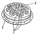
- L'invention sera illustrée plus complètement grâce au dessin annexé qui représente en perspective une balise selon l'invention.
- Sur ce dessin, on voit que l'ensemble des cellules photosensibles 1 sont réparties sur une surface en forme de tronc de cône constituant la face supérieure d'un caisson 2 dans lequel sont enfermés la batterie et les circuits électriques de la balise. Dans l'axe de ce caisson est adapté soit un système optique, tel que 3, soit un système électronique tel qu'une antenne, ou tout autre accessoire, tel que par exemple une mini-station météo dont les renseignements sont transmis à des postes récepteurs fixes, au sol, ou mobiles tel qu'un avion.
- Cette balise peut être montée de manière usuelle aux différents types de bouées maritimes, fluviales ou terrestres ; une autre application encore en est le balisage des pistes d'aéroports, par voie optique ou électronique.
- D'autres réalisations encore pourront être la réalisation de détecteurs d'incendies de forêts et le balisage de stations de pompage notamment dans les pays en voie de développement.
Claims (5)
- Balise dont l'alimentation en courant électrique est assurée par des cellules photovoltaïques (1) fonctionnant avec l'énergie solaire, caractérisée par le fait qu'elle comporte un caisson étanche (2) présentant à sa partie supérieure une forme sensiblement tronconique, les cellules photovoltaïques (1) étant incorporées dans la paroi de la partie sensiblement tronconique dudit caisson qui renferme à son intérieur les batteries destinées à accumuler l'énergie produite par les cellules ainsi que les dispositifs électroniques nécessaires au fonctionnement de la balise.
- Balise selon la revendication 1, caractérisée par le fait qu'elle comporte au centre de sa partie supérieure de forme sensiblement tronconique, un dispositif électronique (3) qui assure le balisage.
- Balise selon l'une quelconque des revendications 1 et 2, caractérisée par le fait que la surface tronconique supérieure du caisson est subdivisée en secteurs plans de petite dimension dans chacun desquels est incorporée une cellule ou un groupe de cellules photovoltaïques (1).
- Balise selon l'une quelconque des revendications 1 et 3, caractérisée par le fait que les cellules photovoltaïques (1) sont incorporées au caisson en étant directement encapsulées dans une masse de matière synthétique transparente telle par exemple que du polyméthacrylate de métyle dopé.
- Balise selon l'une quelconque des revendications précédentes, caractérisée par le fait que la partie supérieure tronconique du caisson a une conicité qui est fonction de la latitude du lieu d'utilisation de la balise.
Priority Applications (1)
| Application Number | Priority Date | Filing Date | Title |
|---|---|---|---|
| AT84440036T ATE64494T1 (de) | 1983-10-24 | 1984-08-08 | Mit sonnenzellen betriebene boje. |
Applications Claiming Priority (2)
| Application Number | Priority Date | Filing Date | Title |
|---|---|---|---|
| FR8317026 | 1983-10-24 | ||
| FR8317026A FR2557369B1 (fr) | 1983-10-24 | 1983-10-24 | Dispositif pour panneaux ou cellules photovoltaiques, groupes en secteurs sur un support en forme de cone, tronc de cone ou tronc de pyramide a n cotes |
Publications (2)
| Publication Number | Publication Date |
|---|---|
| EP0210283A1 EP0210283A1 (fr) | 1987-02-04 |
| EP0210283B1 true EP0210283B1 (fr) | 1991-06-12 |
Family
ID=9293522
Family Applications (1)
| Application Number | Title | Priority Date | Filing Date |
|---|---|---|---|
| EP84440036A Expired - Lifetime EP0210283B1 (fr) | 1983-10-24 | 1984-08-08 | Balise alimentée par cellules solaires |
Country Status (11)
| Country | Link |
|---|---|
| US (1) | US4759735A (fr) |
| EP (1) | EP0210283B1 (fr) |
| JP (1) | JPS60110149A (fr) |
| AT (1) | ATE64494T1 (fr) |
| AU (1) | AU585487B2 (fr) |
| BR (1) | BR8405242A (fr) |
| DE (1) | DE3484714D1 (fr) |
| ES (1) | ES291634Y (fr) |
| FR (1) | FR2557369B1 (fr) |
| PT (1) | PT79395B (fr) |
| ZA (1) | ZA846532B (fr) |
Families Citing this family (39)
| Publication number | Priority date | Publication date | Assignee | Title |
|---|---|---|---|---|
| FR2585182A1 (fr) * | 1985-07-22 | 1987-01-23 | Grands Travaux Urbains Sa | Dispositif autonome, de forme polyedrique, stockant et produisant de l'electricite par l'action de capteurs photovoltoiques a partir de l'irradiation solaire |
| DE3527256A1 (de) * | 1985-07-30 | 1987-02-12 | Norbert Dipl Ing Mosko | Errichtung und bau von statisch feststehenden solaranlagen in pyramidenform |
| JPS62200278A (ja) * | 1986-02-28 | 1987-09-03 | Hitachi Ltd | 路上ビ−コン |
| US5024953A (en) * | 1988-03-22 | 1991-06-18 | Hitachi, Ltd. | Method for producing opto-electric transducing element |
| EP0360892A1 (fr) * | 1988-09-27 | 1990-04-04 | Volker Dipl.-Chem. Genrich | Capteur électronique pour mesurer la quantité de pluie par évacuation de la surface du choc des gouttes uniques |
| US5066256A (en) * | 1989-02-17 | 1991-11-19 | Ward Sr Robert B | Buoy and releasing system for ships in distress |
| US5262756A (en) * | 1991-03-15 | 1993-11-16 | Chien Tseng L | Solar powered warning light |
| FR2674316B1 (fr) * | 1991-03-22 | 1993-07-23 | Pagnol Frederic | Balise alimentee par cellules photovoltauiques. |
| IL98755A (en) * | 1991-07-08 | 1996-01-19 | Chacham Chaim | DEL electronic circuit flashing |
| DE4124075A1 (de) * | 1991-07-19 | 1993-01-21 | Austria Metall | Solarenergievorrichtung |
| US5216972A (en) * | 1991-09-06 | 1993-06-08 | Dufrene John K | Lighted cleat |
| US5121307A (en) * | 1991-09-09 | 1992-06-09 | Moore Charles M | Self contained solar powered strobe light |
| US5225003A (en) * | 1991-12-18 | 1993-07-06 | Ming Che Hong | Multi-purpose solar energy base |
| JPH06350118A (ja) * | 1993-06-11 | 1994-12-22 | Canon Inc | 太陽電池付電子機器 |
| US5453729A (en) * | 1993-07-28 | 1995-09-26 | Chu; Chiu-Tsai | Solar warning light |
| US5537111A (en) * | 1993-10-25 | 1996-07-16 | Martin; John S. | Solar powered aircraft warning device |
| US5785410A (en) * | 1996-05-28 | 1998-07-28 | Branson, Sr.; Michael Del | Electronic road beacon |
| USD386433S (en) * | 1996-11-12 | 1997-11-18 | Regents Of The University Of Minnesota | Buoy with solar cells |
| ATE246387T1 (de) * | 1997-02-19 | 2003-08-15 | Vodafone Holding Gmbh | Vorrichtung zur weiterübermittlung von durch eine zentrale oder erfassungseinheit gesendeten verkehrsinformationen an mindestens ein endgerät |
| US6005517A (en) * | 1997-04-14 | 1999-12-21 | Chrysler Corporation | Test vehicle tracking system |
| FR2762381B1 (fr) * | 1997-04-16 | 1999-10-15 | Laurent Gambourg | Dispositif permettant l'alimentation solaire de balisage lumineux autonome de piste d'atterrissage |
| ES2147159B1 (es) * | 1999-01-07 | 2001-04-16 | Zunibal S L | Boya para la pesca con objeto. |
| US20060076047A1 (en) * | 2001-04-23 | 2006-04-13 | Green David R | Potted domed solar panel capsule and traffic warning lamps incorporating same |
| US20040113817A1 (en) * | 2001-08-07 | 2004-06-17 | Novak Harvey M. | Flashing infrared beacon system |
| WO2003098705A1 (fr) * | 2002-05-17 | 2003-11-27 | Schripsema Jason E | Module photovoltaique comprenant un dissipateur de chaleur reglable, procede de fabrication correspondant |
| KR100555413B1 (ko) * | 2004-12-29 | 2006-03-03 | 서정영 | 태양전지를 이용한 조명 경계석 |
| US9657909B2 (en) | 2005-06-23 | 2017-05-23 | Rsr Sales, Inc. | Self-contained, solar-powered LED illuminator modules and applications thereof |
| US20110292644A1 (en) * | 2005-06-23 | 2011-12-01 | Richard Cohen | Apparatus and method for converting gazing globes and other decorative objects into glow-in-the-dark products |
| ES1062170Y (es) * | 2006-02-10 | 2006-08-16 | Nova Corbyn S A | Poste de señalizacion luminosa. |
| CN200955683Y (zh) * | 2006-09-30 | 2007-10-03 | 徐雪明 | 太阳能围栏发光帽 |
| TW200934978A (en) * | 2008-02-01 | 2009-08-16 | J Touch Corp | Illumination device with energy-conversion module |
| EP2110860A1 (fr) * | 2008-04-17 | 2009-10-21 | National Taiwan University of Science and Technology | Panneau mural et procédé de fabrication |
| US20110005576A1 (en) * | 2009-07-10 | 2011-01-13 | Melvin James Bullen | Personal solar appliance |
| US8531152B2 (en) | 2009-07-10 | 2013-09-10 | Solar Components Llc | Solar battery charger |
| US20110013384A1 (en) * | 2009-07-14 | 2011-01-20 | Maki Solar Technologies Inc. | Maintainable Solar LED Paver/Ground Light, Fixture Thereof, and Installation Method Thereof |
| US8902590B2 (en) | 2012-02-13 | 2014-12-02 | Omnitracs, Llc | Solar powered apparatus having a thermally decoupled solar panel for tracking a portable asset |
| WO2014106179A2 (fr) * | 2012-12-31 | 2014-07-03 | Direct Result Group, LLC | Éclairage en pilier |
| US9458970B2 (en) * | 2014-06-11 | 2016-10-04 | Lazar Izardel | Lamp with LED light bulb |
| US11195390B2 (en) | 2019-07-12 | 2021-12-07 | Federico Crivellaro | Light-signaling device for navigation and a system comprising multiple light-signaling devices for navigation |
Family Cites Families (15)
| Publication number | Priority date | Publication date | Assignee | Title |
|---|---|---|---|---|
| FR1317651A (fr) * | 1963-05-10 | |||
| US3424907A (en) * | 1963-03-04 | 1969-01-28 | Us Navy | Satellite attitude detection system including cosine and spinsate detectors |
| JPS4221820Y1 (fr) * | 1964-07-08 | 1967-12-14 | ||
| US3603952A (en) * | 1969-05-12 | 1971-09-07 | Millard F Smith | Spill sensors |
| US3696286A (en) * | 1970-08-06 | 1972-10-03 | North American Rockwell | System for detecting and utilizing the maximum available power from solar cells |
| US3698025A (en) * | 1970-10-12 | 1972-10-17 | Hitchcock Gas Engine Co Inc Th | Marking buoy |
| JPS5329210B2 (fr) * | 1973-12-22 | 1978-08-19 | ||
| JPS5328751B2 (fr) * | 1974-11-27 | 1978-08-16 | ||
| JPS5299113A (en) * | 1976-02-17 | 1977-08-19 | Hitachi Ltd | Forms inserter |
| GB1592581A (en) * | 1977-06-16 | 1981-07-08 | Bfg Glassgroup | Solar panel |
| FR2450748A1 (fr) * | 1979-03-09 | 1980-10-03 | Centre Nat Etd Spatiales | Procede d'orientation d'un generateur solaire pour satellite geostationnaire et dispositifs pour sa mise en oeuvre |
| FR2469806A1 (fr) * | 1979-11-13 | 1981-05-22 | Stone Platt Crawley Ltd | Agencement de dispositifs photovoltaiques |
| GB2115915A (en) * | 1982-01-13 | 1983-09-14 | Solar Generators Singapore Pte | Self-contained, solar-powered lighting units |
| US4491681A (en) * | 1983-12-08 | 1985-01-01 | The United States Of America As Represented By The United States Department Of Energy | Liquid cooled, linear focus solar cell receiver |
| US4626852A (en) * | 1984-02-01 | 1986-12-02 | Pennwalt Corporation | Buoy lantern system |
-
1983
- 1983-10-24 FR FR8317026A patent/FR2557369B1/fr not_active Expired
-
1984
- 1984-08-08 AT AT84440036T patent/ATE64494T1/de not_active IP Right Cessation
- 1984-08-08 EP EP84440036A patent/EP0210283B1/fr not_active Expired - Lifetime
- 1984-08-08 DE DE8484440036T patent/DE3484714D1/de not_active Expired - Lifetime
- 1984-08-22 ZA ZA846532A patent/ZA846532B/xx unknown
- 1984-10-17 JP JP59218175A patent/JPS60110149A/ja active Pending
- 1984-10-17 BR BR8405242A patent/BR8405242A/pt unknown
- 1984-10-23 ES ES1984291634U patent/ES291634Y/es not_active Expired
- 1984-10-23 PT PT79395A patent/PT79395B/fr not_active IP Right Cessation
- 1984-10-23 AU AU34580/84A patent/AU585487B2/en not_active Ceased
-
1986
- 1986-09-29 US US06/912,499 patent/US4759735A/en not_active Expired - Lifetime
Also Published As
| Publication number | Publication date |
|---|---|
| PT79395B (fr) | 1992-10-30 |
| BR8405242A (pt) | 1985-08-27 |
| JPS60110149A (ja) | 1985-06-15 |
| AU3458084A (en) | 1985-05-09 |
| ES291634Y (es) | 1987-08-01 |
| EP0210283A1 (fr) | 1987-02-04 |
| FR2557369B1 (fr) | 1987-11-06 |
| ES291634U (es) | 1986-12-16 |
| AU585487B2 (en) | 1989-06-22 |
| DE3484714D1 (de) | 1991-07-18 |
| ZA846532B (en) | 1985-04-24 |
| PT79395A (fr) | 1984-11-01 |
| FR2557369A1 (fr) | 1985-06-28 |
| ATE64494T1 (de) | 1991-06-15 |
| US4759735A (en) | 1988-07-26 |
Similar Documents
| Publication | Publication Date | Title |
|---|---|---|
| EP0210283B1 (fr) | Balise alimentée par cellules solaires | |
| Rosa-Clot et al. | Submerged and floating photovoltaic systems: modelling, design and case studies | |
| US9909566B2 (en) | Vertical axis wind turbines | |
| Jenkins et al. | High-bandgap solar cells for underwater photovoltaic applications | |
| US20090129067A1 (en) | Marine lantern controlled by GPS signals | |
| FR2832867A1 (fr) | Systeme spatial de generation photovoltaique | |
| CN106870267A (zh) | 一种能量自供给海上网络通信热点浮动平台 | |
| KR101637911B1 (ko) | 파력 및 온도차 발전장치 | |
| US10418505B2 (en) | Aerodynamic solar pods | |
| JPH11301578A (ja) | 水上浮体装置 | |
| FR2926611A1 (fr) | Aerogenerateur et systeme d'eclairage tel que l'eclairage urbain ou analogue comportant un tel aerogenerateur | |
| CH637584A5 (en) | Craft powered by solar energy | |
| KR20120130810A (ko) | 수상태양광 발전장치의 전도방지 부력체 | |
| CN210979660U (zh) | 磁吸式太阳能遥测遥控航标灯 | |
| CN210327149U (zh) | 一种基于vsat卫星通讯技术的远程电力监控系统 | |
| Treble | Solar cells | |
| Badhoutiya | Advancements in PV Technology-Floating Photovoltaics | |
| US20200300219A1 (en) | Hybrid Kite With Integrated Wind Turbine Generator | |
| FR2561719A1 (fr) | Aerogenerateur aerosustente dit " aerolienne " | |
| FR2479568A1 (fr) | Procede de reglage de la puissance delivree par un systeme de capteurs de rayonnement et dispositifs pour la mise en oeuvre du procede | |
| JPS5934670A (ja) | 太陽光による発電装置の防雪方法 | |
| RU2183351C2 (ru) | Sos-система для автомагистралей | |
| CN107651117A (zh) | 半潜式光学浮标平台 | |
| JPS57371A (en) | Sky wind-driven electric power generator | |
| FR2795569A1 (fr) | Generateur solaire photovoltaique monobloc portatif |
Legal Events
| Date | Code | Title | Description |
|---|---|---|---|
| PUAI | Public reference made under article 153(3) epc to a published international application that has entered the european phase |
Free format text: ORIGINAL CODE: 0009012 |
|
| AK | Designated contracting states |
Kind code of ref document: A1 Designated state(s): AT BE CH DE GB IT LI LU NL SE |
|
| 17P | Request for examination filed |
Effective date: 19870727 |
|
| 17Q | First examination report despatched |
Effective date: 19880905 |
|
| GRAA | (expected) grant |
Free format text: ORIGINAL CODE: 0009210 |
|
| DIN1 | Information on inventor provided before grant (deleted) | ||
| RAP1 | Party data changed (applicant data changed or rights of an application transferred) |
Owner name: PAGNOL, FREDERIC |
|
| AK | Designated contracting states |
Kind code of ref document: B1 Designated state(s): AT BE CH DE GB IT LI LU NL SE |
|
| REF | Corresponds to: |
Ref document number: 64494 Country of ref document: AT Date of ref document: 19910615 Kind code of ref document: T |
|
| REF | Corresponds to: |
Ref document number: 3484714 Country of ref document: DE Date of ref document: 19910718 |
|
| GBT | Gb: translation of ep patent filed (gb section 77(6)(a)/1977) | ||
| ITF | It: translation for a ep patent filed |
Owner name: JACOBACCI & PERANI S.P.A. |
|
| PLBE | No opposition filed within time limit |
Free format text: ORIGINAL CODE: 0009261 |
|
| STAA | Information on the status of an ep patent application or granted ep patent |
Free format text: STATUS: NO OPPOSITION FILED WITHIN TIME LIMIT |
|
| 26N | No opposition filed | ||
| EPTA | Lu: last paid annual fee | ||
| EAL | Se: european patent in force in sweden |
Ref document number: 84440036.6 |
|
| PGFP | Annual fee paid to national office [announced via postgrant information from national office to epo] |
Ref country code: LU Payment date: 19960701 Year of fee payment: 13 |
|
| PGFP | Annual fee paid to national office [announced via postgrant information from national office to epo] |
Ref country code: SE Payment date: 19960702 Year of fee payment: 13 |
|
| PGFP | Annual fee paid to national office [announced via postgrant information from national office to epo] |
Ref country code: AT Payment date: 19960704 Year of fee payment: 13 |
|
| PGFP | Annual fee paid to national office [announced via postgrant information from national office to epo] |
Ref country code: GB Payment date: 19960729 Year of fee payment: 13 |
|
| PGFP | Annual fee paid to national office [announced via postgrant information from national office to epo] |
Ref country code: BE Payment date: 19960829 Year of fee payment: 13 |
|
| PGFP | Annual fee paid to national office [announced via postgrant information from national office to epo] |
Ref country code: NL Payment date: 19960831 Year of fee payment: 13 |
|
| PGFP | Annual fee paid to national office [announced via postgrant information from national office to epo] |
Ref country code: CH Payment date: 19960902 Year of fee payment: 13 |
|
| PGFP | Annual fee paid to national office [announced via postgrant information from national office to epo] |
Ref country code: DE Payment date: 19961028 Year of fee payment: 13 |
|
| PG25 | Lapsed in a contracting state [announced via postgrant information from national office to epo] |
Ref country code: LU Free format text: LAPSE BECAUSE OF NON-PAYMENT OF DUE FEES Effective date: 19970808 Ref country code: GB Free format text: LAPSE BECAUSE OF NON-PAYMENT OF DUE FEES Effective date: 19970808 Ref country code: AT Free format text: LAPSE BECAUSE OF NON-PAYMENT OF DUE FEES Effective date: 19970808 |
|
| PG25 | Lapsed in a contracting state [announced via postgrant information from national office to epo] |
Ref country code: SE Free format text: LAPSE BECAUSE OF NON-PAYMENT OF DUE FEES Effective date: 19970809 |
|
| PG25 | Lapsed in a contracting state [announced via postgrant information from national office to epo] |
Ref country code: LI Free format text: LAPSE BECAUSE OF NON-PAYMENT OF DUE FEES Effective date: 19970831 Ref country code: CH Free format text: LAPSE BECAUSE OF NON-PAYMENT OF DUE FEES Effective date: 19970831 Ref country code: BE Free format text: LAPSE BECAUSE OF NON-PAYMENT OF DUE FEES Effective date: 19970831 |
|
| BERE | Be: lapsed |
Owner name: PAGNOL FREDERIC Effective date: 19970831 |
|
| PG25 | Lapsed in a contracting state [announced via postgrant information from national office to epo] |
Ref country code: NL Free format text: LAPSE BECAUSE OF NON-PAYMENT OF DUE FEES Effective date: 19980301 |
|
| GBPC | Gb: european patent ceased through non-payment of renewal fee |
Effective date: 19970808 |
|
| REG | Reference to a national code |
Ref country code: CH Ref legal event code: PL |
|
| PG25 | Lapsed in a contracting state [announced via postgrant information from national office to epo] |
Ref country code: DE Free format text: LAPSE BECAUSE OF NON-PAYMENT OF DUE FEES Effective date: 19980501 |
|
| EUG | Se: european patent has lapsed |
Ref document number: 84440036.6 |
|
| NLV4 | Nl: lapsed or anulled due to non-payment of the annual fee |
Effective date: 19980301 |