EP0210276B1 - Openable dome roof and method of constructing same - Google Patents
Openable dome roof and method of constructing same Download PDFInfo
- Publication number
- EP0210276B1 EP0210276B1 EP86900282A EP86900282A EP0210276B1 EP 0210276 B1 EP0210276 B1 EP 0210276B1 EP 86900282 A EP86900282 A EP 86900282A EP 86900282 A EP86900282 A EP 86900282A EP 0210276 B1 EP0210276 B1 EP 0210276B1
- Authority
- EP
- European Patent Office
- Prior art keywords
- roof
- beams
- swing
- units
- stationary
- Prior art date
- Legal status (The legal status is an assumption and is not a legal conclusion. Google has not performed a legal analysis and makes no representation as to the accuracy of the status listed.)
- Expired - Lifetime
Links
- 238000000034 method Methods 0.000 title claims description 13
- 230000006835 compression Effects 0.000 claims description 7
- 238000007906 compression Methods 0.000 claims description 7
- 230000007613 environmental effect Effects 0.000 abstract 1
- 238000004804 winding Methods 0.000 abstract 1
- 230000007246 mechanism Effects 0.000 description 13
- 238000010276 construction Methods 0.000 description 9
- 230000008569 process Effects 0.000 description 3
- 230000000386 athletic effect Effects 0.000 description 1
- 238000005452 bending Methods 0.000 description 1
- 230000002301 combined effect Effects 0.000 description 1
- 230000008602 contraction Effects 0.000 description 1
- 230000003247 decreasing effect Effects 0.000 description 1
- 238000007689 inspection Methods 0.000 description 1
- 238000012423 maintenance Methods 0.000 description 1
- 239000000463 material Substances 0.000 description 1
- 230000004048 modification Effects 0.000 description 1
- 238000012986 modification Methods 0.000 description 1
- -1 polytetrafluoroethylene Polymers 0.000 description 1
- 229920001343 polytetrafluoroethylene Polymers 0.000 description 1
- 239000004810 polytetrafluoroethylene Substances 0.000 description 1
- 230000002265 prevention Effects 0.000 description 1
- 230000009467 reduction Effects 0.000 description 1
Images




Classifications
-
- E—FIXED CONSTRUCTIONS
- E04—BUILDING
- E04B—GENERAL BUILDING CONSTRUCTIONS; WALLS, e.g. PARTITIONS; ROOFS; FLOORS; CEILINGS; INSULATION OR OTHER PROTECTION OF BUILDINGS
- E04B7/00—Roofs; Roof construction with regard to insulation
- E04B7/18—Special structures in or on roofs, e.g. dormer windows
-
- E—FIXED CONSTRUCTIONS
- E04—BUILDING
- E04B—GENERAL BUILDING CONSTRUCTIONS; WALLS, e.g. PARTITIONS; ROOFS; FLOORS; CEILINGS; INSULATION OR OTHER PROTECTION OF BUILDINGS
- E04B7/00—Roofs; Roof construction with regard to insulation
- E04B7/16—Roof structures with movable roof parts
- E04B7/166—Roof structures with movable roof parts characterised by a translation movement of the movable roof part, with or without additional movements
-
- E—FIXED CONSTRUCTIONS
- E04—BUILDING
- E04B—GENERAL BUILDING CONSTRUCTIONS; WALLS, e.g. PARTITIONS; ROOFS; FLOORS; CEILINGS; INSULATION OR OTHER PROTECTION OF BUILDINGS
- E04B1/00—Constructions in general; Structures which are not restricted either to walls, e.g. partitions, or floors or ceilings or roofs
- E04B1/32—Arched structures; Vaulted structures; Folded structures
- E04B1/3211—Structures with a vertical rotation axis or the like, e.g. semi-spherical structures
-
- E—FIXED CONSTRUCTIONS
- E04—BUILDING
- E04B—GENERAL BUILDING CONSTRUCTIONS; WALLS, e.g. PARTITIONS; ROOFS; FLOORS; CEILINGS; INSULATION OR OTHER PROTECTION OF BUILDINGS
- E04B1/00—Constructions in general; Structures which are not restricted either to walls, e.g. partitions, or floors or ceilings or roofs
- E04B1/343—Structures characterised by movable, separable, or collapsible parts, e.g. for transport
- E04B1/346—Rotary buildings; Buildings with rotary units, e.g. rooms
-
- E—FIXED CONSTRUCTIONS
- E04—BUILDING
- E04B—GENERAL BUILDING CONSTRUCTIONS; WALLS, e.g. PARTITIONS; ROOFS; FLOORS; CEILINGS; INSULATION OR OTHER PROTECTION OF BUILDINGS
- E04B7/00—Roofs; Roof construction with regard to insulation
- E04B7/08—Vaulted roofs
- E04B7/10—Shell structures, e.g. of hyperbolic-parabolic shape; Grid-like formations acting as shell structures; Folded structures
- E04B7/105—Grid-like structures
-
- E—FIXED CONSTRUCTIONS
- E04—BUILDING
- E04B—GENERAL BUILDING CONSTRUCTIONS; WALLS, e.g. PARTITIONS; ROOFS; FLOORS; CEILINGS; INSULATION OR OTHER PROTECTION OF BUILDINGS
- E04B1/00—Constructions in general; Structures which are not restricted either to walls, e.g. partitions, or floors or ceilings or roofs
- E04B1/32—Arched structures; Vaulted structures; Folded structures
- E04B2001/3217—Auxiliary supporting devices used during erection of the arched structures
-
- E—FIXED CONSTRUCTIONS
- E04—BUILDING
- E04B—GENERAL BUILDING CONSTRUCTIONS; WALLS, e.g. PARTITIONS; ROOFS; FLOORS; CEILINGS; INSULATION OR OTHER PROTECTION OF BUILDINGS
- E04B1/00—Constructions in general; Structures which are not restricted either to walls, e.g. partitions, or floors or ceilings or roofs
- E04B1/32—Arched structures; Vaulted structures; Folded structures
- E04B2001/3235—Arched structures; Vaulted structures; Folded structures having a grid frame
-
- E—FIXED CONSTRUCTIONS
- E04—BUILDING
- E04B—GENERAL BUILDING CONSTRUCTIONS; WALLS, e.g. PARTITIONS; ROOFS; FLOORS; CEILINGS; INSULATION OR OTHER PROTECTION OF BUILDINGS
- E04B1/00—Constructions in general; Structures which are not restricted either to walls, e.g. partitions, or floors or ceilings or roofs
- E04B1/32—Arched structures; Vaulted structures; Folded structures
- E04B2001/3235—Arched structures; Vaulted structures; Folded structures having a grid frame
- E04B2001/3241—Frame connection details
-
- E—FIXED CONSTRUCTIONS
- E04—BUILDING
- E04B—GENERAL BUILDING CONSTRUCTIONS; WALLS, e.g. PARTITIONS; ROOFS; FLOORS; CEILINGS; INSULATION OR OTHER PROTECTION OF BUILDINGS
- E04B1/00—Constructions in general; Structures which are not restricted either to walls, e.g. partitions, or floors or ceilings or roofs
- E04B1/32—Arched structures; Vaulted structures; Folded structures
- E04B2001/3235—Arched structures; Vaulted structures; Folded structures having a grid frame
- E04B2001/3252—Covering details
Definitions
- JP-B-44-15346 discloses an openable dome-shaped roof structure for covering an enclosure defined by a side wall constructed on the ground. Roof units of a movable roof section are provided on the side wall in such a way that the roof units can be pulled out in radial direction to close a central opening. An intermediate support beam is provided between each roof unit and the side wall for supporting and guiding the roof units.
- JP-B-44 15345 shows similar structure of an openable dome-shaped roof.
- the invention uses swing beams for the movable beams supporting the roof units of the movable roof section.
- a preferred arrangement of such swing beams is shown in Figs. 1 through 4.
- This arrangement includes, by way of example, eight swing beams 50a to 50h pivotably joined at each one end to the annular beam 18 of the stationary roof section 12 at points P 1 to Pg which are distributed on the annular beam 18 at regular angular intervals, so that these beams 50a to 50h are swingable in a horizontal plane.
- the slidable joining mechanism need not necessarily include the rollers 55 and 56 and the wire 63, but may include a driving shaft extended within the frame 53 and a wormgear for transmitting the rotary driving force of the driving shaft to the adjacent swing beam, or include a chain and sprockets.
- a semicircular guide member as shown in Fig. 7A around the base end of the swing beam for the stable motion of the swing beam.
- the guide member shown in Fig. 7A is a semicircular guide rail 80 properly protruding for guiding the swing motion of the beam 50 from the inner surface of the annular beam 18.
- the guide rail 80 is provided on a substantially U-shaped guide rail supporting frame 82 fixed to the annular beam 18 and the girder 81 of the stationary roof section 12.
- the guide rail 80 supports and guides the swing beam 50 for sliding-swing motion through an angle of 90 degrees between a position where the swing beam 50 is located near the annular beam 18 and a position where the same is located substantially at right angles to the annular beam 18.
- the sliding surface of the guide rail 80 is formed of a material having a small coefficient of friction, such as a polytetrafluoroethylene.
- knuckles fixed to the annular beam 18 and the swing beam 50, respectively.
- the swing beam 50 is pivotably joined to the annular beam 18 by joining the knuckles 83 and 84 with a pin 85.
- Indicated at 86 is a guide rail extending on the upper surface of the swing beam 50.
- the guide rail 86 is continuous with a guide rail 88 extending on the upper surface of a radial girder 87 of the stationary roof section 12.
- the guide rails 86 and 88 guide the roof units of the movable roof section 16 for sliding movement.
- the swing beam 50 is driven for sliding-swing motion along the guide rail 80 by suitable driving means.
- the central opening 14 When the central opening 14 is fully opened, the outer end of the swing beam 50 comes into abutment with the inner surface of the annular beam 18.
- the load is not concentrated only on the pin 85, but is distributed to the pin 85 and the guide rail supporting frame 82. Therefore, the swing beam 50 is supported rigidly, the bending of the swing beam 50 is reduced and the swing beam 50 is able to swing stably and safely.
- the swing beam 50 can be automatically and correctly located at a position as illustrated in Fig. 7A by providing a stopper at an appropriate position on the guide rail 80 and by making the outer end surface of the swing beam 50 come into abutment with the inner surface of the annular beam 18.
- the driving means comprises a hydraulic jack 90.
- the base end 90a of a cylinder of the hydraulic jack 90 is joined pivotably to a strut 91 extending between the annular beam 18 and the girder 81 of the stationary roof section 12, while the free end 90b of a piston rod is connected to the swing beam 50 at a predetermined position by a connecting member 92.
- the hydraulic jack 90 is extended or contracted to turn the swing beam 50 along the guide rail 80.
- the driving means for driving the swing beam 50 need not necessarily be limited to the hydraulic jack but may be any suitable means such as a device including a wire for controlling the swing beam 50.
- the swing beam 50 is driven individually for swing motion, which is different from the preceding embodiments.
- the swing beam 50 is retractable and is extended after being turned to a position indicated by continuous lines in Fig. 7B to engage the interlocking heads of the adjacent swing beams for obtaining the strength enough to support the roof units.
- a construction method according to the present invention will be described hereinafter.
- the method is mainly directed to the construction of the stationary roof section of the above-described openable dome-shaped roof structure.
- the processes of a preferred embodiment of the method are shown in Figs. 8, 9 and 10.
- a numeral 102 denotes a practically circular structure constructed around the ground 100
- the structure 102 has an external wall (a side wall) and stands declining in steps from the external wall toward the ground 100.
- the above-mentioned stationary roof section 12 is built on the external wall.
- the stationary roof section comprises a plurality of frame members 104 arranged around the center O of the structure 102.
- An outer or base end of each frame member 104 is secured pivotably with a pin 108 on a fixed annular beam 106 fixedly disposed along the upper end of the external wall of the structure 102.
- An arcuate compression beam 110 is attached to each frame member 104 to define the inner side, namely, the side facing the central opening.
- Each frame 104 is assembled with the outer side being supported on the annular beam 106 by the pin 108 and the inner side being placed in the ground 100.
- the components of a roofing structure such as struts, principal rafters, purlins and common rafters, and roofing plates or films are assembled on the frame 104 to complete a roof unit for the stationary roof section 12.
- the tension members 116 are wound to turn the frames (stationary roof units) 104 on the corresponding pins 108 so that the respective inner sides of the units 104 are lifted up.
- the clearances between the adjacent compression beams 110 are decreased, which is absorbed by the contraction of the expansion joints 112.
- the clearances decrease until the units 104 are turned to a horizontal position, and then increase again as the units 104 are turned further upward.
- the expansion joints are fastened rigidly to complete a stationary roof section having a central opening. Thereafter, the swing beams 50 are turned until the free ends thereof are interlocked at the center O of the central opening to complete the dome-shaped roof structure as illustrated in Fig. 10.
- areas A shaded with dots correspond to the roofing extended over the roof units 104.
- Triangular areas B between the adjacent areas A may be roofed by extending the roofing over the units 104 or may be roofed separately after fixing the units 104 in place.
- the temporary posts may be removed after the stationary roof section has been completed or may be reserved for use as supports or as maintenance facilities.
- the stationary roof units are assembled with the annular beam 106 being fixed on the external wall, however, the annular beam 106 need not necessarily be secured to the external wall in advance but it is also possible to lift up the annular beam 106 onto the external wall and to fix the same at a predetermined position after assembling the stationary roof section entirely on the ground.
Landscapes
- Engineering & Computer Science (AREA)
- Architecture (AREA)
- Physics & Mathematics (AREA)
- Electromagnetism (AREA)
- Civil Engineering (AREA)
- Structural Engineering (AREA)
- Conveying And Assembling Of Building Elements In Situ (AREA)
- Tents Or Canopies (AREA)
Abstract
Description
- The invention relates to an openable dome-shaped roof structure according to the preamble of
claim 1 as well as a method of constructing the same. - JP-B-44-15346 discloses an openable dome-shaped roof structure for covering an enclosure defined by a side wall constructed on the ground. Roof units of a movable roof section are provided on the side wall in such a way that the roof units can be pulled out in radial direction to close a central opening. An intermediate support beam is provided between each roof unit and the side wall for supporting and guiding the roof units. JP-B-44 15345 shows similar structure of an openable dome-shaped roof.
- If a stadium of large diameter should be covered by such a known structure, it is difficult to provide a large extension of the roof units.
- It is an object of the present invention to provide an openable dome-shaped roof structure according to the preamble of
claim 1 in such a way that it can be used for large diameter stadiums. This object is achieved according to the invention by the features in the characterizing part ofclaim 1. - It is another object of the present invention to provide a method of securely and efficiently constructing such an openable dome-shaped roof structure.
- This is achieved by the features in claim 3.
- Thus, according to the present invention, since the stationary roof units are assembled substantially on the ground level, they can be assembled safely and only the least preparatory work is required. Furthermore, since the roof units of the stationary roof section can be assembled individually, the roof can be efficiently constructed.
- The above and other objects, features and advantages of the present invention will become more apparent from the following description of the preferred embodiments thereof when taken in conjunction with the accompanying drawings.
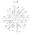
- Fig. 1 is a plan view of exemplary swing beams;
- Fig. 2 is an enlarged plan view of the swing beams of Fig. 1;
- Figs. 3A, 3B and 3C are a sectional view, a side elevation and a plan view, respectively, of a sliding-pivot mechanism of the swing beams;
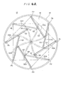
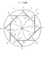
- Figs. 4A and 4B are plan views of the swing beams during swing motion and at the completion of the swing motion, respectively;
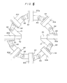
- Fig. 5 is an enlarged fragmentary view showing another example of swing beams;
- Fig. 6 is a plan view illustrating the swing motion of the swing beams of Fig. 5;
- Fig. 7A is a perspective view of a swing beam supporting mechanism;
- Fig. 7B is a plan view showing an example of a swing beam driving mechanism;
- Figs. 8, 9 and 10 are a sectional view, an enlarged fragmentary plan view and a plan view, respectively, of assistance in explaining a construction method according to an embodiment of the present invention, in which Fig. 10 the construction is completed; and
- Fig. 11 is an illustration of assistance in explaining a construction method according to another embodiment of the present invention.
- The invention uses swing beams for the movable beams supporting the roof units of the movable roof section. A preferred arrangement of such swing beams is shown in Figs. 1 through 4. This arrangement includes, by way of example, eight
swing beams 50a to 50h pivotably joined at each one end to theannular beam 18 of thestationary roof section 12 at points P1 to Pg which are distributed on theannular beam 18 at regular angular intervals, so that thesebeams 50a to 50h are swingable in a horizontal plane. - When the
central opening 14 is closed with the roof units as shown in Fig. 1, theswing beams 50a to 50h extend radially outward from the center of thecentral opening 14 and, as illustrated in Fig. 2, the diametricallyopposite swing beams link device 51. Theswing beam 50a and the circumferentiallyadjacent swing beam 50b in a clockwise direction are joined together by acircumferential link device 52. Similarly, theswing beams device 52. Theselink devices - The circumferentially adjacent swing beams are paired, that is, the
swing beams - The mechanism for slidably and pivotably connecting the
swing beam 50h to thebeam 50a, for instance, is shown in Figs. 3A to 3C. Theswing beam 50a is fixedly provided on one side wall thereof facing theswing beam 50h with aframe 53 having a longitudinal slit 53a and extending from the free end of theswing beam 50a to a position near the point P1 on theannular beam 18, within which frame 53 aguide rail 54 having an I-shaped cross section extends longitudinally over the entire length thereof. A pair oflarger rollers 55 and a pair ofsmaller rollers 56 are provided so as to roll along the opposite surfaces of the flange of theguide rail 54, respectively. Therollers spindles 58 on a pair ofholding plates 57 extending through the slit 53a outside theframe 53. - Three
rotary sheaves 61 are supported byspindles 58 on supportingarms 60 attached to the outer surfaces of theholding plates 57, respectively, so as to roll along the side surface of the flange of theguide rail 54. Awire 63 fixed at one end thereof to theframe 53 by ananchor 62, is wound around thesheaves 61 andsheaves 64 which are mounted on the free end of theframe 53. The other end ofwire 63 extends, viasmall sheaves 65 disposed at suitable intervals within theframe 53, toward the pivoted end or base of theswing beam 50a. - A connecting
arm 68 fastened by abolt 67 to theswing beam 50h at a position near the free end thereof, is pivotably joined to the outer end of theholding plates 57 by means of a connectingpin 66. The connectingarm 68 may be joined to theswing beam 50h by, for example, a dovetail joint so as to be slidable perpendicularly to theswing beam 50h. - When the
wires 63 are pulled by a winch or the like after disengaging thelink devices swing beams swing beams annular beam 18 within a plane containing thecentral opening 14. Consequently, as is best seen from Fig. 4A showing the swing beams in the process of opening swing motion and Fig. 4B showing the disposition of the swing beams at the completion of the opening motion thereof, a substantially octagonal space defined by thebeams 50a to 50h and within thecentral opening 14 expands gradually. Upon the alignment of theswing beams 50a to 50h with axes passing the alternate pivotal points P1 to Pa on theannular beam 18, the swing motion of thebeams 50a to 50h is terminated. - When the
wires 63 are loosened, theswing beams 50a to 50h turn in the opposite direction to return to the position shown in Fig. 1 in which they extend radially from the center of theopening 14. - Each swing beam is provided with guide means, not shown, such as a guide rail, for movably supporting the roof units of the movable roof section 16.
- Figs. 5 and 6 show a swing beam mechanism in a modification of the above-mentioned structure. The modified swing beam mechanism will be described only in respects different from the above-mentioned one to avoid duplication.
Retractable members 70 are built in theswing beams link device 51 provided between theswing beams link devices 52 provided between thebeams swing beams Brackets 71 are provided on the respective free ends of theretractable members 70. Slidable joining mechanisms each including aframe 53 are provided on the side walls of theswing beams plates 57 of the slidable joining mechanisms are pivotably connected to thebrackets 71 bypins 66, respectively. - Thus, in this modified swing beam mechanism, the two diametrically
opposite swing beams retractable members 70 and all theswing beams 50a to 50h are connected pivotably one to another for relative sliding motion. - As shown in Fig. 6, all the
swing beams 50a to 50h are always connected to the adjacent ones as they are turned on the pivotal points with theretractable members 70 retracting or extending, to expand or to contract a substantially octagonal space in the central area of theopening 14. Since all theswing beams 50a to 50h swing in an integral linkage to open or to close thecentral opening 14, this modified swing beam mechanism is more stable and more advantageous in respect of structural reliability than the swing beam mechanism of the preceding embodiment. - The slidable joining mechanism need not necessarily include the
rollers wire 63, but may include a driving shaft extended within theframe 53 and a wormgear for transmitting the rotary driving force of the driving shaft to the adjacent swing beam, or include a chain and sprockets. - When the above-mentioned swing beam is employed for supporting the roof units of the movable roof section 16, it is preferable to provide a semicircular guide member as shown in Fig. 7A around the base end of the swing beam for the stable motion of the swing beam. The guide member shown in Fig. 7A is a
semicircular guide rail 80 properly protruding for guiding the swing motion of thebeam 50 from the inner surface of theannular beam 18. Theguide rail 80 is provided on a substantially U-shaped guiderail supporting frame 82 fixed to theannular beam 18 and thegirder 81 of thestationary roof section 12. Theguide rail 80 supports and guides theswing beam 50 for sliding-swing motion through an angle of 90 degrees between a position where theswing beam 50 is located near theannular beam 18 and a position where the same is located substantially at right angles to theannular beam 18. In order to reduce the frictional resistance of the sliding surface of theguide rail 80 to the least possible extent, the sliding surface of theguide rail 80 is formed of a material having a small coefficient of friction, such as a polytetrafluoroethylene. - In Fig. 7A, indicated at 83 and 84 are knuckles fixed to the
annular beam 18 and theswing beam 50, respectively. Theswing beam 50 is pivotably joined to theannular beam 18 by joining theknuckles pin 85. Indicated at 86 is a guide rail extending on the upper surface of theswing beam 50. Theguide rail 86 is continuous with aguide rail 88 extending on the upper surface of aradial girder 87 of thestationary roof section 12. The guide rails 86 and 88 guide the roof units of the movable roof section 16 for sliding movement. - The
swing beam 50 is driven for sliding-swing motion along theguide rail 80 by suitable driving means. When thecentral opening 14 is fully opened, the outer end of theswing beam 50 comes into abutment with the inner surface of theannular beam 18. During the swing motion of thebeam 50, the load is not concentrated only on thepin 85, but is distributed to thepin 85 and the guiderail supporting frame 82. Therefore, theswing beam 50 is supported rigidly, the bending of theswing beam 50 is reduced and theswing beam 50 is able to swing stably and safely. - The
swing beam 50 can be automatically and correctly located at a position as illustrated in Fig. 7A by providing a stopper at an appropriate position on theguide rail 80 and by making the outer end surface of theswing beam 50 come into abutment with the inner surface of theannular beam 18. - An exemplary driving means for driving the
swing beam 50 for sliding-swing movement is shown in Fig. 7B. The driving means comprises ahydraulic jack 90. The base end 90a of a cylinder of thehydraulic jack 90 is joined pivotably to astrut 91 extending between theannular beam 18 and thegirder 81 of thestationary roof section 12, while thefree end 90b of a piston rod is connected to theswing beam 50 at a predetermined position by a connectingmember 92. Thehydraulic jack 90 is extended or contracted to turn theswing beam 50 along theguide rail 80. The driving means for driving theswing beam 50 need not necessarily be limited to the hydraulic jack but may be any suitable means such as a device including a wire for controlling theswing beam 50. - In the embodiment shown in Figs. 7A and 7B, the
swing beam 50 is driven individually for swing motion, which is different from the preceding embodiments. Preferably, theswing beam 50 is retractable and is extended after being turned to a position indicated by continuous lines in Fig. 7B to engage the interlocking heads of the adjacent swing beams for obtaining the strength enough to support the roof units. - A construction method according to the present invention will be described hereinafter. The method is mainly directed to the construction of the stationary roof section of the above-described openable dome-shaped roof structure. The processes of a preferred embodiment of the method are shown in Figs. 8, 9 and 10.
- Referring to Figs. 8 to 10, indicated at 100 is the ground of an athletic stadium such as a baseball ground, and a numeral 102 denotes a practically circular structure constructed around the
ground 100, Thestructure 102 has an external wall (a side wall) and stands declining in steps from the external wall toward theground 100. The above-mentionedstationary roof section 12 is built on the external wall. - The stationary roof section comprises a plurality of
frame members 104 arranged around the center O of thestructure 102. An outer or base end of eachframe member 104 is secured pivotably with apin 108 on a fixedannular beam 106 fixedly disposed along the upper end of the external wall of thestructure 102. Anarcuate compression beam 110 is attached to eachframe member 104 to define the inner side, namely, the side facing the central opening. - The
adjacent compression beams 110 are joined together by hydraulic or mechanical expansion joints, respectively. The base end ofswing beam 50 is pivotably secured to thecompression beam 110 at the middle of the inner surface thereof so as to be swingable along thesemicircular guide rail 80 fixed to the inner surface of thecompression beam 110. Although the openable dome-shaped roof structure is explained herein as employing the swing beams for convenience sake, naturally, the roof structure may employ any one of the above-mentioned movable beams or fixed beams. - A temporary post is set up for every
frame member 104 at a position near the outer end thereof. Atension member 116 having one end connected to the inner side of theframe 104 is extended via the top of thetemporary post 114. - Each
frame 104 is assembled with the outer side being supported on theannular beam 106 by thepin 108 and the inner side being placed in theground 100. After theframe 104 has been assembled, the components of a roofing structure, such as struts, principal rafters, purlins and common rafters, and roofing plates or films are assembled on theframe 104 to complete a roof unit for thestationary roof section 12. - After all stationary roof units have been completed, the
tension members 116 are wound to turn the frames (stationary roof units) 104 on the correspondingpins 108 so that the respective inner sides of theunits 104 are lifted up. As theunits 104 are turned upward, the clearances between theadjacent compression beams 110 are decreased, which is absorbed by the contraction of the expansion joints 112. The clearances decrease until theunits 104 are turned to a horizontal position, and then increase again as theunits 104 are turned further upward. After theunits 104 have been disposed at a predetermined pitch, the expansion joints are fastened rigidly to complete a stationary roof section having a central opening. Thereafter, the swing beams 50 are turned until the free ends thereof are interlocked at the center O of the central opening to complete the dome-shaped roof structure as illustrated in Fig. 10. - In Fig. 10, areas A shaded with dots correspond to the roofing extended over the
roof units 104. Triangular areas B between the adjacent areas A may be roofed by extending the roofing over theunits 104 or may be roofed separately after fixing theunits 104 in place. The temporary posts may be removed after the stationary roof section has been completed or may be reserved for use as supports or as maintenance facilities. - Another method according to the present invention is shown in Fig. 11. In this embodiment, the
stationary roof units 104 are lifted up by acrane 120 installed on theground 100. The use of a lifting machine in combination with thecrane 120 will enable theunits 104 to be lifted up more securely. - According to the embodiments described hereinbefore, the stationary roof units are assembled with the
annular beam 106 being fixed on the external wall, however, theannular beam 106 need not necessarily be secured to the external wall in advance but it is also possible to lift up theannular beam 106 onto the external wall and to fix the same at a predetermined position after assembling the stationary roof section entirely on the ground. - As is apparent from the foregoing description, according to the present invention, the processes of constructing the frame members and finishing the roof units are carried out practically on the ground level with the frames being supported on the ground, and hence large-scale timbering including temporary standards is unnecessary and temporary works including the construction of scaffolding and preventions of danger can be reduced greatly. Furthermore, the reduction of construction work on an elevated level effectively reduces labor. Since the method according to the present invention greatly reduces preparatory works including timbering, the work for constructing the roof structure can be started at an early time. Still further, since the plural frame members and roof units can be simultaneously fabricated, the period of the construction work can be curtailed. Moreover, assembling the stationary roof units practically on the ground level facilitates inspection and eliminates the danger of work on an elevated level. The combined effect of the above-mentioned advantages reduces the construction cost, and hence the method according to the present invention is particularly suitable for an openable dome-shaped roof structure which, in general, is costly.
Claims (4)
Applications Claiming Priority (12)
| Application Number | Priority Date | Filing Date | Title |
|---|---|---|---|
| JP9136/85 | 1985-01-23 | ||
| JP9137/85 | 1985-01-23 | ||
| JP60009136A JPS61169540A (en) | 1985-01-23 | 1985-01-23 | Openable dome roof |
| JP60009137A JPS61169541A (en) | 1985-01-23 | 1985-01-23 | Openable dome roof |
| JP13165785A JP2693751B2 (en) | 1985-06-19 | 1985-06-19 | Openable roof movable beam |
| JP131657/85 | 1985-06-19 | ||
| JP12396185U JPH0510086Y2 (en) | 1985-08-14 | 1985-08-14 | |
| JP123961/85U | 1985-08-14 | ||
| JP17361385U JPH0510087Y2 (en) | 1985-11-13 | 1985-11-13 | |
| JP173613/85U | 1985-11-13 | ||
| JP60257638A JPS62117956A (en) | 1985-11-19 | 1985-11-19 | Construction of dome shaped roof |
| JP257638/85 | 1985-11-19 |
Publications (3)
| Publication Number | Publication Date |
|---|---|
| EP0210276A1 EP0210276A1 (en) | 1987-02-04 |
| EP0210276A4 EP0210276A4 (en) | 1987-05-13 |
| EP0210276B1 true EP0210276B1 (en) | 1990-12-05 |
Family
ID=27548183
Family Applications (1)
| Application Number | Title | Priority Date | Filing Date |
|---|---|---|---|
| EP86900282A Expired - Lifetime EP0210276B1 (en) | 1985-01-23 | 1985-12-26 | Openable dome roof and method of constructing same |
Country Status (7)
| Country | Link |
|---|---|
| US (1) | US4751800A (en) |
| EP (1) | EP0210276B1 (en) |
| KR (1) | KR930000119B1 (en) |
| AU (1) | AU577438B2 (en) |
| DE (1) | DE3580846D1 (en) |
| GB (1) | GB2179975B (en) |
| WO (1) | WO1986004371A1 (en) |
Cited By (1)
| Publication number | Priority date | Publication date | Assignee | Title |
|---|---|---|---|---|
| CN104234200A (en) * | 2014-09-24 | 2014-12-24 | 东南大学 | Ring-by-ring lifting mounting method for suspendome cable-bar system |
Families Citing this family (51)
| Publication number | Priority date | Publication date | Assignee | Title |
|---|---|---|---|---|
| WO1986006123A1 (en) * | 1985-04-09 | 1986-10-23 | Ohbayashi-Gumi, Ltd. | Openable dome roof and method of constructing same |
| AU590631B2 (en) * | 1986-04-08 | 1989-11-09 | Ohbayashi-Gumi Ltd. | Retractable roof structure |
| NO160936C (en) * | 1987-02-24 | 1989-06-21 | Arne Martin Lerstoel | BUILDING CONSTRUCTION DEVICE. |
| GB8805183D0 (en) * | 1988-03-04 | 1988-04-07 | Brown G | Three-dimensional structure |
| JPH0765372B2 (en) * | 1988-11-24 | 1995-07-19 | 清水建設株式会社 | Retractable roof |
| US5189851A (en) * | 1989-01-24 | 1993-03-02 | Kajima Corporation | Movable dome-type roof for structure |
| US5257481A (en) * | 1989-01-25 | 1993-11-02 | George S. Reppas | Retractable dome |
| CA2013359C (en) * | 1989-03-30 | 1993-06-08 | Hiroki Muramoto | Openable roof apparatus |
| AU615384B2 (en) * | 1989-04-10 | 1991-09-26 | Ohbayashi Corporation | Openable dome-shaped roof structure |
| US5203125A (en) * | 1989-08-16 | 1993-04-20 | Shimizu Construction Co., Ltd. | Openable roof |
| US5035093A (en) * | 1990-03-05 | 1991-07-30 | Blenkhorn And Sawle Limited | Building structure with fixed center and movable perimeter roof sections |
| JP2885947B2 (en) * | 1991-02-22 | 1999-04-26 | 前田建設工業株式会社 | Retractable roof structure |
| US5373668A (en) * | 1993-06-09 | 1994-12-20 | Shulman; Neil B. | Cottage with removable roof |
| US5778603A (en) * | 1996-10-29 | 1998-07-14 | Reppas; George S. | Retractable dome |
| US6003269A (en) * | 1997-04-07 | 1999-12-21 | Mcree; Richard T. | Retractable covering for spaces |
| US6082054A (en) * | 1998-08-27 | 2000-07-04 | Silberman; Cyril J. | Retractable stadium roofs and transport mechanism therefor |
| GB9918919D0 (en) * | 1999-08-12 | 1999-10-13 | Tomlinson Andrew D | Improvements to retracting roof systems for buildings |
| US6754994B2 (en) | 2000-03-01 | 2004-06-29 | Farahmand Jahanpour | Retractable roof |
| CN1332103C (en) * | 2000-03-01 | 2007-08-15 | 法拉曼德·贾汉波尔 | retractable roof |
| US6415556B1 (en) | 2000-07-03 | 2002-07-09 | Uni-Systems, Inc. | Transport mechanism for large structures such as retractable stadium rooves |
| US6718696B2 (en) | 2001-01-23 | 2004-04-13 | Uni-Systems, Llc | Movable wall for stadium |
| US6789360B2 (en) | 2001-01-23 | 2004-09-14 | Uni-Systems, Llc | Retractable roof system for stadium |
| US6698141B2 (en) | 2001-01-23 | 2004-03-02 | Uni-Systems, Llc | Convertible stadium and method of operating |
| RU2213830C2 (en) * | 2001-07-13 | 2003-10-10 | Глущенко Владимир Федорович | Arched construction of arched structure |
| US7520091B2 (en) * | 2004-07-09 | 2009-04-21 | Friedman Daniel B | Adaptable roof system |
| US20060032156A1 (en) * | 2004-07-22 | 2006-02-16 | Jean Simard | Openable roof |
| US8186107B2 (en) * | 2005-03-09 | 2012-05-29 | Uni-Systems, Llc | Cable drive and control system for movable stadium roof panels |
| US7594360B2 (en) * | 2005-03-09 | 2009-09-29 | Uni-Systems, Llc | Lateral release mechanism for movable roof panels |
| ITRM20050184A1 (en) * | 2005-04-14 | 2006-10-15 | L A S P System Italia S R L | ROOF STRUCTURE WITH DIFFERENT FUNCTIONS, FOR EXAMPLE THE ANTI-SEISMIC STRUCTURE, OF PROTECTION FROM WIND BURST, AND MORE AGAIN. |
| US7559174B2 (en) * | 2006-05-19 | 2009-07-14 | Charles Hoberman | Covering structure having links and stepped overlapping panels both of which are pivotable between extended position and a retracted position in which the panels are stacked |
| CA2768048C (en) * | 2008-07-14 | 2020-07-07 | Delaney Technologies Inc. | Self-supporting pier for a retractable roof system for a large building structure |
| US11063553B2 (en) * | 2008-11-17 | 2021-07-13 | Kbfx Llc | Solar carports, solar-tracking carports, and methods |
| US10277159B2 (en) | 2008-11-17 | 2019-04-30 | Kbfx Llc | Finished multi-sensor units |
| US20140259899A1 (en) * | 2013-03-15 | 2014-09-18 | Alain Poivet | Movable building crown |
| US20110308173A1 (en) * | 2009-09-04 | 2011-12-22 | Forsland Kent H | Movable building structure |
| WO2011088113A1 (en) * | 2010-01-12 | 2011-07-21 | Cabreeco Companies Llc | Movable enclosure |
| US8905054B2 (en) * | 2012-09-20 | 2014-12-09 | EZ as a Drink Productions, Inc. | Protrusive structure apparatus |
| CN103306412B (en) * | 2013-06-25 | 2015-10-21 | 国核工程有限公司 | A kind of Open-type dome steel structure |
| US8978313B1 (en) * | 2014-04-04 | 2015-03-17 | Antonio Pilla | Precipitation deflector |
| CN105275122A (en) * | 2014-07-24 | 2016-01-27 | 冯玉廷 | Large-scale venue instant movable curtain top |
| CN104131639B (en) * | 2014-08-11 | 2016-08-31 | 哈尔滨工业大学 | Inflated type reticulated shell-string structure |
| CN104763053B (en) * | 2015-03-25 | 2017-01-11 | 东南大学 | Foldable and unfoldable connecting rod-inflatable membrane structure |
| US10450746B2 (en) * | 2015-09-30 | 2019-10-22 | George Pul | Folded dome like retractable opening structure and method |
| US12294332B2 (en) | 2015-12-15 | 2025-05-06 | Kbfx Llc | Solar carports, solar-tracking carports, and methods |
| CN105604190B (en) * | 2015-12-18 | 2017-12-05 | 上海交通大学 | A kind of prefabricated assembled air film concrete-shell and preparation method thereof |
| US10487874B2 (en) | 2016-08-31 | 2019-11-26 | Geiger Gossen Campbell Engineers P.C. | Non-linear bearing release for large moveable structures |
| CN106592864B (en) * | 2016-12-30 | 2019-03-12 | 江苏沪宁钢机股份有限公司 | A kind of steel structural roof beam string segmentation installation method |
| CN112031171B (en) * | 2020-08-25 | 2022-04-12 | 广东电网有限责任公司 | Movable maintenance working shed |
| US12492549B2 (en) * | 2022-04-30 | 2025-12-09 | Vasconi Venture LLC | Housing including roof/cover adapted with retractable panels in hinged connection to outwardly movable side walls |
| CN115324260A (en) * | 2022-08-09 | 2022-11-11 | 中建北域建设工程有限公司 | Rotation type is air film structure for roof that opens and shuts |
| CN120331491B (en) * | 2025-06-05 | 2025-09-26 | 北京建工集团有限责任公司 | Spherical self-balancing steel reticulated shell construction method |
Family Cites Families (14)
| Publication number | Priority date | Publication date | Assignee | Title |
|---|---|---|---|---|
| DE235066C (en) * | ||||
| US1193833A (en) * | 1916-08-08 | Octagonal portable summer-house | ||
| CA772349A (en) * | 1967-11-28 | Kabushiki Kaisha Tomoegumi Tekkosho | Structure with skylight opening closable by divisional roof panels | |
| US1240182A (en) * | 1916-10-30 | 1917-09-18 | Frank H Douthitt | Silo-roof. |
| US2716993A (en) * | 1952-06-02 | 1955-09-06 | Thomas H Codrick | Folding tent frame |
| SE320475B (en) * | 1968-06-17 | 1970-02-09 | Kallin R | |
| SU318257A1 (en) * | 1970-03-23 | 1970-11-30 | Одесский ордена Трудового Красного Знамени политехнический институт | Reactor Bolshakov-Tseveleva |
| SE341674B (en) * | 1971-06-11 | 1972-01-10 | Hoeganaes Ab | |
| CA938073A (en) * | 1971-11-22 | 1973-12-11 | W. Tuuri Elmer | Prefabricated and demountable building |
| DE2823500A1 (en) * | 1978-05-30 | 1979-12-13 | Losch Ohg | DEVICE FOR SLIDING A SLIDING ROOF |
| JPS6085137A (en) * | 1983-10-14 | 1985-05-14 | 株式会社匠工務所 | Screen opening and closing method and apparatus |
| JPS6088744A (en) * | 1983-10-18 | 1985-05-18 | 株式会社匠工務所 | Special structure roof wall apparatus |
| JP2690666B2 (en) * | 1992-09-01 | 1997-12-10 | 京セラ株式会社 | Manufacturing method of semiconductor device storage package |
| JPH0688744A (en) * | 1992-09-07 | 1994-03-29 | Fujita Corp | Method for orienting slope rupture position by ae measurement |
-
1985
- 1985-12-26 US US06/882,979 patent/US4751800A/en not_active Expired - Lifetime
- 1985-12-26 WO PCT/JP1985/000725 patent/WO1986004371A1/en not_active Ceased
- 1985-12-26 KR KR1019860700389A patent/KR930000119B1/en not_active Expired - Fee Related
- 1985-12-26 GB GB08613497A patent/GB2179975B/en not_active Expired
- 1985-12-26 AU AU53050/86A patent/AU577438B2/en not_active Ceased
- 1985-12-26 EP EP86900282A patent/EP0210276B1/en not_active Expired - Lifetime
- 1985-12-26 DE DE8686900282T patent/DE3580846D1/en not_active Expired - Lifetime
Cited By (1)
| Publication number | Priority date | Publication date | Assignee | Title |
|---|---|---|---|---|
| CN104234200A (en) * | 2014-09-24 | 2014-12-24 | 东南大学 | Ring-by-ring lifting mounting method for suspendome cable-bar system |
Also Published As
| Publication number | Publication date |
|---|---|
| EP0210276A4 (en) | 1987-05-13 |
| AU577438B2 (en) | 1988-09-22 |
| KR870700114A (en) | 1987-03-14 |
| GB2179975B (en) | 1988-09-01 |
| DE3580846D1 (en) | 1991-01-17 |
| GB2179975A (en) | 1987-03-18 |
| AU5305086A (en) | 1986-08-13 |
| KR930000119B1 (en) | 1993-01-09 |
| EP0210276A1 (en) | 1987-02-04 |
| WO1986004371A1 (en) | 1986-07-31 |
| GB8613497D0 (en) | 1986-07-09 |
| US4751800A (en) | 1988-06-21 |
Similar Documents
| Publication | Publication Date | Title |
|---|---|---|
| US4751800A (en) | Openable dome-shaped roof structure | |
| US5309693A (en) | Frame structure | |
| US5062243A (en) | Openable roof | |
| US5146719A (en) | Space tension chord arch dome reinforced with tension members and method for building same | |
| US5088263A (en) | Construction apparatus and construction method | |
| US4706419A (en) | Openable dome-shaped roof structure | |
| CA1283766C (en) | Openable dome-shaped roof structure and a method of constructing the same | |
| WO1990012167A1 (en) | Frame structure | |
| US4276733A (en) | Method of constructing and erecting a dome-shaped structure | |
| JP3061560B2 (en) | Tent warehouse and its construction method | |
| US5150556A (en) | Chord truss roof structure | |
| JPH0571225A (en) | Temporarily set roof of complete weather type | |
| US4282696A (en) | Method for fabricating and erecting unitary structural elements | |
| JPS5912827B2 (en) | Demolition method for tower-like structures and scaffolding equipment for demolition | |
| JPH09144197A (en) | Method for constructing roof of stadium | |
| JP2836369B2 (en) | Roof structure of temporary beam assembly device for building construction | |
| JPH0776933A (en) | Large roof erection method | |
| JP2858891B2 (en) | Construction method of large span dome roof | |
| CA1279458C (en) | Openable dome-shaped roof structure and a method of constructing the same | |
| JP2863802B2 (en) | Construction method of dome frame | |
| JPH0586651A (en) | Method and apparatus for constructing column and beam | |
| SU1133370A1 (en) | Tent structure | |
| JPS62117956A (en) | Construction of dome shaped roof | |
| JPH06330639A (en) | Temporary tent equipped with opening/closing mechanism | |
| JPH084116A (en) | Traveling method for space truss having curved surface |
Legal Events
| Date | Code | Title | Description |
|---|---|---|---|
| PUAI | Public reference made under article 153(3) epc to a published international application that has entered the european phase |
Free format text: ORIGINAL CODE: 0009012 |
|
| AK | Designated contracting states |
Kind code of ref document: A1 Designated state(s): DE FR IT |
|
| 17P | Request for examination filed |
Effective date: 19870120 |
|
| A4 | Supplementary search report drawn up and despatched |
Effective date: 19870513 |
|
| 17Q | First examination report despatched |
Effective date: 19881130 |
|
| GRAA | (expected) grant |
Free format text: ORIGINAL CODE: 0009210 |
|
| ITF | It: translation for a ep patent filed | ||
| AK | Designated contracting states |
Kind code of ref document: B1 Designated state(s): DE FR IT |
|
| REF | Corresponds to: |
Ref document number: 3580846 Country of ref document: DE Date of ref document: 19910117 |
|
| ET | Fr: translation filed | ||
| PLBE | No opposition filed within time limit |
Free format text: ORIGINAL CODE: 0009261 |
|
| STAA | Information on the status of an ep patent application or granted ep patent |
Free format text: STATUS: NO OPPOSITION FILED WITHIN TIME LIMIT |
|
| 26N | No opposition filed | ||
| ITTA | It: last paid annual fee | ||
| PGFP | Annual fee paid to national office [announced via postgrant information from national office to epo] |
Ref country code: DE Payment date: 19991202 Year of fee payment: 15 |
|
| PGFP | Annual fee paid to national office [announced via postgrant information from national office to epo] |
Ref country code: FR Payment date: 19991216 Year of fee payment: 15 |
|
| PG25 | Lapsed in a contracting state [announced via postgrant information from national office to epo] |
Ref country code: FR Free format text: LAPSE BECAUSE OF NON-PAYMENT OF DUE FEES Effective date: 20010831 |
|
| REG | Reference to a national code |
Ref country code: FR Ref legal event code: ST |
|
| PG25 | Lapsed in a contracting state [announced via postgrant information from national office to epo] |
Ref country code: DE Free format text: LAPSE BECAUSE OF NON-PAYMENT OF DUE FEES Effective date: 20011002 |