EP0210032A2 - Ostomie Vorrichtung - Google Patents
Ostomie Vorrichtung Download PDFInfo
- Publication number
- EP0210032A2 EP0210032A2 EP86305402A EP86305402A EP0210032A2 EP 0210032 A2 EP0210032 A2 EP 0210032A2 EP 86305402 A EP86305402 A EP 86305402A EP 86305402 A EP86305402 A EP 86305402A EP 0210032 A2 EP0210032 A2 EP 0210032A2
- Authority
- EP
- European Patent Office
- Prior art keywords
- bag
- coupling element
- extension
- filter
- wall
- Prior art date
- Legal status (The legal status is an assumption and is not a legal conclusion. Google has not performed a legal analysis and makes no representation as to the accuracy of the status listed.)
- Granted
Links
Images


Classifications
-
- A—HUMAN NECESSITIES
- A61—MEDICAL OR VETERINARY SCIENCE; HYGIENE
- A61F—FILTERS IMPLANTABLE INTO BLOOD VESSELS; PROSTHESES; DEVICES PROVIDING PATENCY TO, OR PREVENTING COLLAPSING OF, TUBULAR STRUCTURES OF THE BODY, e.g. STENTS; ORTHOPAEDIC, NURSING OR CONTRACEPTIVE DEVICES; FOMENTATION; TREATMENT OR PROTECTION OF EYES OR EARS; BANDAGES, DRESSINGS OR ABSORBENT PADS; FIRST-AID KITS
- A61F5/00—Orthopaedic methods or devices for non-surgical treatment of bones or joints; Nursing devices ; Anti-rape devices
- A61F5/44—Devices worn by the patient for reception of urine, faeces, catamenial or other discharge; Colostomy devices
- A61F5/441—Devices worn by the patient for reception of urine, faeces, catamenial or other discharge; Colostomy devices having venting or deodorant means, e.g. filters ; having antiseptic means, e.g. bacterial barriers
Definitions
- the present invention relates to ostomy appliances.
- the invention relates to a bag side coupling element for use on or with an ostomy bag, and to bags including such elements.
- a bag side coupling element for an ostomy bag.
- the bag side coupling element has a flange which will surround a stomal orifice, and it has a coupling portion by means of which the bag side coupling element can be coupled to a body side coupling element of an ostomy bag.
- the body side coupling element of the ostomy bag has a flange which has an extension at an upper part thereof, i.e., towards the top of the bag when the bag is connected to the body mounted coupling element.
- the extension on the bag is capable of serving in use to accommodate a filter, to act as a grip tab, or to stiffen the bag in its upper region.
- the extension also accommodates a gas vent means and a filter.
- the filter is preferably a snap-in filterJ
- the flange and its extension are integrally molded from plastic.
- a disc filter is disposed within a housing whose peripheral wall is formed integrally with the extension.
- the coupling portion has an extension which is formed with a flat surface adapted to receive an adhesive means.
- the coupling portion is formed as a so-called “snap lock coupling" in which an interengaging rib and channel effect a connection between a bag-side and a body side ostomy coupling element.
- the ostomy bag 5 including the present invention may be better understood by firstly considering the bag-side coupling element 7 illustrated in FIGS. 3 and 4.
- the bag-side coupling element 7 comprises a flat annular flange 10 having a stomal orifice 12.
- the flange 10 is integral with an extension 14.
- the extension 14 is substantially circular, as shown in FIG. 4, and has a shallow cylindrical housing 21 having a peripheral wall 16 and a top wall 20.
- a hole 18 is formed in a central region of the top wall 20. The purpose of the hole 18 is to allow exit of gases to the atmosphere as explained more fully hereinafter.
- the ostomy bag 5 illustrated in FIGS. 1 and 2 has front and rear walls 24, 26, respectively, secured together by a peripheral weld 28.
- a perforated sheet 30 extending only over the lower part of the bag 5 is attached to the ostomy bag 5 by the peripheral weld 28.
- the top edge 32 of the perforated sheet 30 is not attached to the front bag wall 24.
- One purpose of the perforated sheet 30 is to provide a surface which is less cold to the touch so that when this portion of the ostomy bag 5 contacts the skin of the wearer comfort is improved.
- the bag-side coupling element 7 includes a flange 10.
- the coupling element 7 is secured by welds 36, 38 to the front wall 24 of the ostomy bag 5.
- Each of these welds 36, 38 is substantially circular.
- the weld 38 surrounds a hole 40 in an upper region of the front wall 24.
- the hole 40 is located within the confines of the wall 16 of the shallow cylindrical 21 portion of the bag-side coupling element 5.
- the coupling element 7 has a flange 10 which presents a flat surface away from the bag 5, that is to say towards the body-side coupling element with which it is intended to cooperate.
- a series of adhesive annuli may be used to connect the bag 5 to a body-side ostomy coupling member.
- the extension 14 of the coupling element 7 is secured to the bag 5 by the weld 38 and it preferably contains a filter pad 42 (see FIG. 2) chosen to be a snug fit within the shallow cylindrical space 21 defined by the walls 16, 20. While reference is being made to separate walls it will be appreciated that the whole bag-side coupling element 7 illustrated in FIG. 3 is made from a single piece of plastic, for example, by injection molding.
- the extension 14 stiffens the upper portion of the bag wall 24 and effectively prevents undesired drooping of the bag 5. It also houses the filter 42.
- the hole 40, the filter 42, and the hole 18 constitute the exit path for any flatus gases which have entered the bag 5 after having been discharged from the stoma of the wearer.
- Another useful feature of the extension 14 is that it provides a tab which can be gripped by the wearer of the bag 5, thereby facilitating removal of the bag 5 to change it. If it is not desired to provide a filter pad 42, then the hole 40 in the upper region of the bag wall 24 could be omitted.
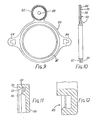
- the illustrated bag-side coupling element 7, shown in front view in FIG. 5 and in a sectional view in FIG. 6, has a flange 50 and an extension 52.
- a circular central stomal orifice 54 in the flange 50 although that orifice 54 need not necessarily be circular.
- the extension 52 has a central circular hole 56 which is aligned with a pre-punched hole in the adjacent wall of the ostomy bag 5 when in use.
- the extension 52 has a peripheral wall 60 containing an internal peripheral groove 62 therein. Spaced just inwardly of this wall 60 is a circular upraised rib 66 projecting from the base wall 68 of the extension 52.
- the configuration is best illustrated in FIG. 7.
- FIG. 8 is an enlargement of part of FIG. 6 which illustrates the provision of a shielding and guiding rim 74 whose purpose is to limit the possibility of any discharged faecal material becoming lodged in any crack or crevice which may exist where the bag joins the surface 50a.
- the purpose of the groove 62 is to engage and receive a counterpart rim or rib on a filter cover as will be described hereinafter.
- the purpose of the rib 66 is to engage the adjacent surface of a flat circular disc filter which is to be accommodated in the extension 52 in such a way as to apply some compression effect at a circular line spaced inwardly from the exterior of the filter disc. This is to inhibit exiting gases from bypassing the filter.
- FIGS. 9 and 10 illustrate a bag-side coupling element 80 having an extension 82 and tabs 84 for the attachment of a belt, not shown.
- the bag-side coupling element 80 has a peripheral channel section 85 for receiving a counterpart body-side coupling element.
- the extension 82 has a base wall 86 which has a central hole 88 therein. In use, the hole 88 is aligned with a pre-punched hole in the adjacent wall of an ostomy bag which is suitably secured to the coupling element 80 over the surfaces indicated at 90.
- the extension 82 as shown in FIG. 11, has a detailed configuration similar to that shown in FIG. 7, that is to say there is an internal groove 62, an upraised rib 66, and a bevel 70. The purpose of these parts is the same as that described in connection with FIGS. 6 and 7.
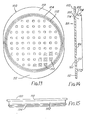
- the filter cover 101 illustrated in FIGS. 13 and 14, has a top wall 100, connected to a substantially cylindrical wall 102.
- the filter cover 101 is preferably made of plastic such as a high density polyethylene, but any material suitable for the "snap fit" connection may be used.
- the wall 102 has an external rib or detent 104 for engagement in the groove 62 described above.
- the top wall 100 has square holes 106 therein and is of substantially oval shape as seen in plan, having flanges 110, 112 which extend beyond the confines of the wall 102.
- the flanges 110, 112 are provided to enable a user to separate the filter cover 101 from the extension, e.g., by inserting a finger nail underneath the flange 110 and lifting.
- a shallow cylindrical space 114 accommodates a circular disc filter. Any known form of circular disc filter may be employed.
- exit holes 106 for the gas which are of tapered configuration the walls of the holes tapering inwardly so that the hole cross-sectional area at the inner surface 120 (FIG. 13) of the wall 100 is less than the hole cross-sectional area at the outer surface 122 of the wall.
- the filter cover 101 can readily be attached to the extension 52 or 82 as the case may be, by pushing it on so that the snap fitting parts 104 and 62 interengage.
- a filter disc is normally placed within the space 114 before snapping the two parts together.
- the raised rib 66 pinches the filter at a circular location space just inwardly of its outer periphery thereby ensuring that any gas leaving the ostomy bag through the hole 56 or 88 and entering the filter housing defined by the interengaging walls 60 and 102 (or 82 and 102) is constrained to pass through the filter to reach the exit holes 106 and cannot by-pass the filter.
- a new filter can easily be inserted without removing the ostomy bag. Hence, there is no need to uncouple the body side and bag side couplings when changing a filter, nor any need to remove the body side attachment member from the peristomal skin region. Hence, undesired disturbance of this skin region is minimized.
Landscapes
- Health & Medical Sciences (AREA)
- Epidemiology (AREA)
- Nursing (AREA)
- Orthopedic Medicine & Surgery (AREA)
- Engineering & Computer Science (AREA)
- Biomedical Technology (AREA)
- Heart & Thoracic Surgery (AREA)
- Vascular Medicine (AREA)
- Life Sciences & Earth Sciences (AREA)
- Animal Behavior & Ethology (AREA)
- General Health & Medical Sciences (AREA)
- Public Health (AREA)
- Veterinary Medicine (AREA)
- Orthopedics, Nursing, And Contraception (AREA)
Priority Applications (1)
| Application Number | Priority Date | Filing Date | Title |
|---|---|---|---|
| AT86305402T ATE70430T1 (de) | 1985-07-16 | 1986-07-14 | Ostomie vorrichtung. |
Applications Claiming Priority (4)
| Application Number | Priority Date | Filing Date | Title |
|---|---|---|---|
| GB8517870 | 1985-07-16 | ||
| GB08517870A GB2177924A (en) | 1985-07-16 | 1985-07-16 | Side coupling element for ostomy appliances |
| GB8531257 | 1985-12-19 | ||
| GB08531257A GB2177926B (en) | 1985-07-16 | 1985-12-19 | Ostomy appliance |
Publications (3)
| Publication Number | Publication Date |
|---|---|
| EP0210032A2 true EP0210032A2 (de) | 1987-01-28 |
| EP0210032A3 EP0210032A3 (en) | 1988-05-11 |
| EP0210032B1 EP0210032B1 (de) | 1991-12-18 |
Family
ID=26289535
Family Applications (1)
| Application Number | Title | Priority Date | Filing Date |
|---|---|---|---|
| EP19860305402 Expired EP0210032B1 (de) | 1985-07-16 | 1986-07-14 | Ostomie Vorrichtung |
Country Status (3)
| Country | Link |
|---|---|
| EP (1) | EP0210032B1 (de) |
| JP (1) | JPH0775615B2 (de) |
| DE (1) | DE3682968D1 (de) |
Cited By (2)
| Publication number | Priority date | Publication date | Assignee | Title |
|---|---|---|---|---|
| EP0358316A3 (en) * | 1988-08-15 | 1990-04-11 | E.R. Squibb & Sons, Inc. | Ostomy bag and gas filter for same |
| EP0305432B1 (de) * | 1987-03-02 | 1992-10-28 | E.R. Squibb & Sons, Inc. | Filter zum anbringen an einem ostomiebeutel |
Family Cites Families (4)
| Publication number | Priority date | Publication date | Assignee | Title |
|---|---|---|---|---|
| US2555086A (en) * | 1950-06-07 | 1951-05-29 | Etna Appliance And Equipment C | Colostomy protector |
| GB1595906A (en) * | 1978-04-28 | 1981-08-19 | Kingsdown Medical Consultants | Surgical dressing |
| DE2928274A1 (de) * | 1978-07-19 | 1980-02-07 | Matburn Holdings Ltd | Chirurgischer auffang-beutel |
| GB2094153B (en) * | 1981-03-09 | 1985-09-04 | Johnson & Johnson | Colostomy appliance and pressure relief valve therefor |
-
1986
- 1986-07-14 EP EP19860305402 patent/EP0210032B1/de not_active Expired
- 1986-07-14 DE DE8686305402T patent/DE3682968D1/de not_active Expired - Lifetime
- 1986-07-15 JP JP16773786A patent/JPH0775615B2/ja not_active Expired - Lifetime
Cited By (2)
| Publication number | Priority date | Publication date | Assignee | Title |
|---|---|---|---|---|
| EP0305432B1 (de) * | 1987-03-02 | 1992-10-28 | E.R. Squibb & Sons, Inc. | Filter zum anbringen an einem ostomiebeutel |
| EP0358316A3 (en) * | 1988-08-15 | 1990-04-11 | E.R. Squibb & Sons, Inc. | Ostomy bag and gas filter for same |
Also Published As
| Publication number | Publication date |
|---|---|
| JPS6264362A (ja) | 1987-03-23 |
| EP0210032A3 (en) | 1988-05-11 |
| DE3682968D1 (de) | 1992-01-30 |
| EP0210032B1 (de) | 1991-12-18 |
| JPH0775615B2 (ja) | 1995-08-16 |
Similar Documents
| Publication | Publication Date | Title |
|---|---|---|
| EP0089138B1 (de) | Kupplung für einen Ostomiebeutel | |
| US5125917A (en) | Ostomy appliances | |
| EP0274862B1 (de) | Kupplung für Ostomiebeutel | |
| EP1578218B1 (de) | Kinderlätzchen mit einer aus aufgereihten kügelchen bestehenden befestigung | |
| EP0747026B1 (de) | Selbstausrichtende Ostomievorrichtung | |
| CA1187758A (en) | Drainable collection pouch and filter assembly therefor | |
| IE47191B1 (en) | Improvements in ostomy bags | |
| GB1571657A (en) | Ostomy bag | |
| CA2281550C (en) | Convex insert system for an ostomy appliance | |
| GB2177924A (en) | Side coupling element for ostomy appliances | |
| US4559048A (en) | Coupling for an ostomy bag | |
| US4940461A (en) | Filter for attachment to an ostomy bag | |
| EP0210032A2 (de) | Ostomie Vorrichtung | |
| EP0373795B1 (de) | Ostomiekupplung | |
| EP0680736B1 (de) | Ostomiekupplung | |
| GB1595906A (en) | Surgical dressing | |
| GB2177301A (en) | Ostomy bags, particularly ileostomy bags, and gas filter arrangements for same | |
| CA1213490A (en) | Coupling for an ostomy bag | |
| CA1162809A (en) | Ostomy bags | |
| IE47192B1 (en) | Ostomy bag attachment device |
Legal Events
| Date | Code | Title | Description |
|---|---|---|---|
| PUAI | Public reference made under article 153(3) epc to a published international application that has entered the european phase |
Free format text: ORIGINAL CODE: 0009012 |
|
| AK | Designated contracting states |
Kind code of ref document: A2 Designated state(s): AT BE CH DE FR GB IT LI LU NL SE |
|
| PUAL | Search report despatched |
Free format text: ORIGINAL CODE: 0009013 |
|
| AK | Designated contracting states |
Kind code of ref document: A3 Designated state(s): AT BE CH DE FR GB IT LI LU NL SE |
|
| 17P | Request for examination filed |
Effective date: 19881022 |
|
| RAP1 | Party data changed (applicant data changed or rights of an application transferred) |
Owner name: E.R. SQUIBB & SONS, INC. |
|
| 17Q | First examination report despatched |
Effective date: 19900427 |
|
| GRAA | (expected) grant |
Free format text: ORIGINAL CODE: 0009210 |
|
| AK | Designated contracting states |
Kind code of ref document: B1 Designated state(s): AT BE CH DE FR GB IT LI LU NL SE |
|
| REF | Corresponds to: |
Ref document number: 70430 Country of ref document: AT Date of ref document: 19920115 Kind code of ref document: T |
|
| ET | Fr: translation filed | ||
| REF | Corresponds to: |
Ref document number: 3682968 Country of ref document: DE Date of ref document: 19920130 |
|
| ITF | It: translation for a ep patent filed | ||
| PLBE | No opposition filed within time limit |
Free format text: ORIGINAL CODE: 0009261 |
|
| STAA | Information on the status of an ep patent application or granted ep patent |
Free format text: STATUS: NO OPPOSITION FILED WITHIN TIME LIMIT |
|
| 26N | No opposition filed | ||
| EPTA | Lu: last paid annual fee | ||
| EAL | Se: european patent in force in sweden |
Ref document number: 86305402.9 |
|
| PGFP | Annual fee paid to national office [announced via postgrant information from national office to epo] |
Ref country code: SE Payment date: 20000705 Year of fee payment: 15 |
|
| PGFP | Annual fee paid to national office [announced via postgrant information from national office to epo] |
Ref country code: LU Payment date: 20000710 Year of fee payment: 15 |
|
| PGFP | Annual fee paid to national office [announced via postgrant information from national office to epo] |
Ref country code: AT Payment date: 20000712 Year of fee payment: 15 Ref country code: CH Payment date: 20000712 Year of fee payment: 15 |
|
| PGFP | Annual fee paid to national office [announced via postgrant information from national office to epo] |
Ref country code: BE Payment date: 20000918 Year of fee payment: 15 |
|
| PG25 | Lapsed in a contracting state [announced via postgrant information from national office to epo] |
Ref country code: LU Free format text: LAPSE BECAUSE OF NON-PAYMENT OF DUE FEES Effective date: 20010714 Ref country code: AT Free format text: LAPSE BECAUSE OF NON-PAYMENT OF DUE FEES Effective date: 20010714 |
|
| PG25 | Lapsed in a contracting state [announced via postgrant information from national office to epo] |
Ref country code: SE Free format text: LAPSE BECAUSE OF NON-PAYMENT OF DUE FEES Effective date: 20010715 |
|
| PG25 | Lapsed in a contracting state [announced via postgrant information from national office to epo] |
Ref country code: LI Free format text: LAPSE BECAUSE OF NON-PAYMENT OF DUE FEES Effective date: 20010731 Ref country code: CH Free format text: LAPSE BECAUSE OF NON-PAYMENT OF DUE FEES Effective date: 20010731 Ref country code: BE Free format text: LAPSE BECAUSE OF NON-PAYMENT OF DUE FEES Effective date: 20010731 |
|
| REG | Reference to a national code |
Ref country code: GB Ref legal event code: IF02 |
|
| BERE | Be: lapsed |
Owner name: E.R. SQUIBB & SONS INC. Effective date: 20010731 |
|
| EUG | Se: european patent has lapsed |
Ref document number: 86305402.9 |
|
| REG | Reference to a national code |
Ref country code: CH Ref legal event code: PL |
|
| PGFP | Annual fee paid to national office [announced via postgrant information from national office to epo] |
Ref country code: NL Payment date: 20050703 Year of fee payment: 20 |
|
| PGFP | Annual fee paid to national office [announced via postgrant information from national office to epo] |
Ref country code: DE Payment date: 20050707 Year of fee payment: 20 |
|
| PGFP | Annual fee paid to national office [announced via postgrant information from national office to epo] |
Ref country code: FR Payment date: 20050708 Year of fee payment: 20 |
|
| PGFP | Annual fee paid to national office [announced via postgrant information from national office to epo] |
Ref country code: GB Payment date: 20050713 Year of fee payment: 20 |
|
| PG25 | Lapsed in a contracting state [announced via postgrant information from national office to epo] |
Ref country code: IT Free format text: LAPSE BECAUSE OF NON-PAYMENT OF DUE FEES Effective date: 20050714 |
|
| REG | Reference to a national code |
Ref country code: GB Ref legal event code: PE20 |
|
| PG25 | Lapsed in a contracting state [announced via postgrant information from national office to epo] |
Ref country code: GB Free format text: LAPSE BECAUSE OF EXPIRATION OF PROTECTION Effective date: 20060713 |
|
| PG25 | Lapsed in a contracting state [announced via postgrant information from national office to epo] |
Ref country code: NL Free format text: LAPSE BECAUSE OF EXPIRATION OF PROTECTION Effective date: 20060714 |
|
| NLV7 | Nl: ceased due to reaching the maximum lifetime of a patent |
Effective date: 20060714 |