EP0210003A2 - Dämpfungsbestimmung einer Koppeloptik - Google Patents
Dämpfungsbestimmung einer Koppeloptik Download PDFInfo
- Publication number
- EP0210003A2 EP0210003A2 EP86305112A EP86305112A EP0210003A2 EP 0210003 A2 EP0210003 A2 EP 0210003A2 EP 86305112 A EP86305112 A EP 86305112A EP 86305112 A EP86305112 A EP 86305112A EP 0210003 A2 EP0210003 A2 EP 0210003A2
- Authority
- EP
- European Patent Office
- Prior art keywords
- light
- fiber
- optical fiber
- optical
- intensity
- Prior art date
- Legal status (The legal status is an assumption and is not a legal conclusion. Google has not performed a legal analysis and makes no representation as to the accuracy of the status listed.)
- Withdrawn
Links
Images
Classifications
-
- G—PHYSICS
- G01—MEASURING; TESTING
- G01M—TESTING STATIC OR DYNAMIC BALANCE OF MACHINES OR STRUCTURES; TESTING OF STRUCTURES OR APPARATUS, NOT OTHERWISE PROVIDED FOR
- G01M11/00—Testing of optical apparatus; Testing structures by optical methods not otherwise provided for
- G01M11/30—Testing of optical devices, constituted by fibre optics or optical waveguides
- G01M11/33—Testing of optical devices, constituted by fibre optics or optical waveguides with a light emitter being disposed at one fibre or waveguide end-face, and a light receiver at the other end-face
-
- G—PHYSICS
- G01—MEASURING; TESTING
- G01M—TESTING STATIC OR DYNAMIC BALANCE OF MACHINES OR STRUCTURES; TESTING OF STRUCTURES OR APPARATUS, NOT OTHERWISE PROVIDED FOR
- G01M11/00—Testing of optical apparatus; Testing structures by optical methods not otherwise provided for
- G01M11/30—Testing of optical devices, constituted by fibre optics or optical waveguides
- G01M11/35—Testing of optical devices, constituted by fibre optics or optical waveguides in which light is transversely coupled into or out of the fibre or waveguide, e.g. using integrating spheres
Definitions
- the present invention is related to copending U.S. Serial Nos. 545,413 filed October 25, 1983, and 630,921 filed July 16, 1984, assigned to the assigned of the present invention, the disclosures of which are incorporated herein by reference.
- the present invention relates to a method and apparatus for measuring a loss across an optical fiber splice joining first and second optical fibers.
- a common prior art method of determining a signal loss across an optical fiber splice is to utilize an optical time domain reflectometer (OTDR) subsequent to formation of the splice.
- OTDR optical time domain reflectometer
- the use of an OTDR is disadvantageous since it is a relatively expensive piece of equipment to be made available for such a limited purpose, and its use requires that an OTDR operator be made available at a signal injection/signal extraction point of an optical fiber, usually a termination thereof, located usually remotely from the splice.
- the optical fibers can be secured in any manner, preferred manners being fusing the optical fiber ends together or alternatively glueing the optical fiber ends together by curing a liquid adhesive within which the fiber ends are moved.
- the loss is preferentially illustrated as a dB loss and is determined by summing three values, a first value being reflective of an X misalignment, the second value being reflective of a Y misalignment, and the third value being reflective of loss formed by the securing operation.
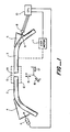
- Figure 1 is a schematic illustration of a method and apparatus constructed according to one preferred embodiment of the invention.
- Figure 1 illustrates an apparatus and method for determining a splice loss incurred by joining first and second ends 13, 14 of first and second fibers 2, 3 together.
- the fiber ends 13, 14 are moved relative to one another in X, Y, and Z directions illustrated by arrows 15, 16, and 17 respectively using a moving means 11, one example being a step motor.
- a moving means 11 one example being a step motor.
- Preferentially, light is locally injected into the upstream optical fiber 2 using a side light launch injection technique, one example of which is disclosed in U.S. application serial nos. 437,053 and 614,884, assigned to the assignee of the present invention, the disclosures of which are incorporated herein by reference.
- light is injected into the upstream optical fiber 2 through its buffer at a bend by injecting an optical signal from a light source 6 into an optical coupler 4 and then into the fiber 2 at the bent section thereof.
- the signal could be injected into the optical fiber 2 at a straight section thereof through its buffer using the source 6 and optical coupler 4 at a straight section of the optical fiber, with the fiber being bent downstream from a point of injection to mode couple light into a core of the optical fiber 2.
- Light is withdrawn from the downstream optical fiber 3 through its buffer at a bend using another optical coupler 5 and a light detector 8, preferably at a bend as illustrated, though local light detection can be achieved by first bending the downstream optical fiber 3 and then disposing an optical coupler 5 at a straight section of the optical fiber 3 downstream from the bend while using the detector 8.
- An intensity of an optical signal 9 detected by the detector 8 is transmitted to a microcomputer such as a central processing unit 10 which preferably can also be in communication with the light source 6.
- feedback control is uti lized between light intensities detected by the central processing unit 10 and light intensities emitted by the source 6 such that the ends 13, 14 of the first and second optical fibers 2, 3 are optimally aligned so as to maximize detected signal 9 to the extent practicable.
- the first and second optical fibers 2, 3 are secured to each other, two methods being curing a liquid adhesive surrounding the first and second ends 13, 14, an alternative embodiment being fusing or melting the first and second ends 13, 14 together.
- an attenuation across the splice formed by the securing means 12 is determined by utilizing a first maximum signal intensity found when moving the fiber ends 13, 14 relative to each other in the X direction, using a second maximum light intensity found when moving the optical fiber ends 13, 14 relative to each other in the Y direction, using a third optical signal intensity found when the optical fiber ends 13, 14 are optimally substantially aligned by the step motor 11 using the feedback control described, and by using a fourth signal intensity withdrawn from the optical fiber 3 subsequent to securing the first and second fiber ends 13, 14 together.
- the signal intensity subsequent to permanently joining the ends 13, 14 is utilized in conjunction with the third signal intensity measured subsequent to obtaining optimal substantial alignment prior to actually securing the optical fibers together.
- the detected signal 9 varies in time and generally decreases with time due to creep of the optical couplers 4, 5 when the optical fibers 2, 3 are pressed thereagainst, and a further correction factor can be utilized to compensate for this creep effect, and without such compensation the otherwise measured loss would be erroneously high.
- An example of the use of the method and apparatus of the invention is that an attenuation across a splice can be deter strictlymined by utilizing the following algorithms: where dB is the attenuation expressed in dB, dB x is an attenuation caused by an X axis misalignment, dB y is an attenuation caused by a Y axis misalignment, dB secure is an attenuation caused by the securing operation, dB drift is an attenuation caused by changes in signal intensity created by creep of the optical couplers 4, 5, S1 is a first maximum signal detected when moving the fiber ends 13, 14 in an X direction, S2 is a second maximum signal detected when moving the optical fiber ends 13, 14 in the Y direction, S3 is a third optical signal detected subsequent to optimally substantially aligning the optical fiber ends 13, 14, S4 is a fourth optical signal detected subsequent to securing the optical fiber ends 13, 14 together, x is an emperi
Landscapes
- Physics & Mathematics (AREA)
- Optics & Photonics (AREA)
- Chemical & Material Sciences (AREA)
- Analytical Chemistry (AREA)
- General Physics & Mathematics (AREA)
- Mechanical Coupling Of Light Guides (AREA)
- Testing Of Optical Devices Or Fibers (AREA)
- Light Guides In General And Applications Therefor (AREA)
Applications Claiming Priority (2)
| Application Number | Priority Date | Filing Date | Title |
|---|---|---|---|
| US06/755,408 US4659217A (en) | 1985-07-15 | 1985-07-15 | Determining splice attenuation |
| US755408 | 1985-07-15 |
Publications (2)
| Publication Number | Publication Date |
|---|---|
| EP0210003A2 true EP0210003A2 (de) | 1987-01-28 |
| EP0210003A3 EP0210003A3 (de) | 1987-12-02 |
Family
ID=25039018
Family Applications (1)
| Application Number | Title | Priority Date | Filing Date |
|---|---|---|---|
| EP86305112A Withdrawn EP0210003A3 (de) | 1985-07-15 | 1986-07-01 | Dämpfungsbestimmung einer Koppeloptik |
Country Status (3)
| Country | Link |
|---|---|
| US (1) | US4659217A (de) |
| EP (1) | EP0210003A3 (de) |
| JP (1) | JPS6219730A (de) |
Cited By (2)
| Publication number | Priority date | Publication date | Assignee | Title |
|---|---|---|---|---|
| EP0253090A3 (de) * | 1986-07-12 | 1988-05-04 | ANT Nachrichtentechnik GmbH | Verfahren zum Ausrichten zweier Lichtleitfaserenden auf stirnseitigen Kontakt |
| EP0421657A3 (en) * | 1989-10-05 | 1992-10-14 | Hughes Aircraft Company | Measurement of optical attenuation along the length of bent optical fibers |
Families Citing this family (7)
| Publication number | Priority date | Publication date | Assignee | Title |
|---|---|---|---|---|
| JPH0675023B2 (ja) * | 1988-01-30 | 1994-09-21 | 株式会社フジクラ | 光ファイバの接続損失推定法 |
| US5179275A (en) * | 1990-11-13 | 1993-01-12 | Siemens Aktiengesellschaft | Method for measuring light being coupled into and out of a light waveguide |
| US5315365A (en) * | 1992-06-17 | 1994-05-24 | Laser Precision Corp. | Macrobend splice loss tester for fiber optic splices with silicon gel cushion on optical coupling blocks |
| US5357332A (en) * | 1992-08-11 | 1994-10-18 | Photonix Industries | Apparatus for, and method of, determining the effectiveness of a splice of optical fiber |
| DE4236806A1 (de) * | 1992-10-30 | 1994-05-05 | Siemens Ag | Optisches Dämpfungsglied, Verfahren zu seiner Herstellung und ein hierzu geeigentes thermisches Spleißgerät |
| JP2015004762A (ja) * | 2013-06-20 | 2015-01-08 | 三菱電線工業株式会社 | 光ファイバの接続方法 |
| CN112629821B (zh) * | 2020-11-17 | 2023-10-27 | 中国移动通信集团江苏有限公司 | 光缆位置的确定方法、装置、电子设备及存储介质 |
Family Cites Families (1)
| Publication number | Priority date | Publication date | Assignee | Title |
|---|---|---|---|---|
| DE3429947A1 (de) * | 1984-08-14 | 1986-02-27 | Siemens AG, 1000 Berlin und 8000 München | Vorrichtung zur einkopplung von licht in einen lichtwellenleiter |
-
1985
- 1985-07-15 US US06/755,408 patent/US4659217A/en not_active Expired - Fee Related
-
1986
- 1986-07-01 EP EP86305112A patent/EP0210003A3/de not_active Withdrawn
- 1986-07-01 JP JP61155908A patent/JPS6219730A/ja active Pending
Cited By (3)
| Publication number | Priority date | Publication date | Assignee | Title |
|---|---|---|---|---|
| EP0253090A3 (de) * | 1986-07-12 | 1988-05-04 | ANT Nachrichtentechnik GmbH | Verfahren zum Ausrichten zweier Lichtleitfaserenden auf stirnseitigen Kontakt |
| US4798442A (en) * | 1986-07-12 | 1989-01-17 | Ant Nachrichtentechnik Gmbh | Method of aligning two optical fiber ends for frontal contact |
| EP0421657A3 (en) * | 1989-10-05 | 1992-10-14 | Hughes Aircraft Company | Measurement of optical attenuation along the length of bent optical fibers |
Also Published As
| Publication number | Publication date |
|---|---|
| US4659217A (en) | 1987-04-21 |
| JPS6219730A (ja) | 1987-01-28 |
| EP0210003A3 (de) | 1987-12-02 |
Similar Documents
| Publication | Publication Date | Title |
|---|---|---|
| US4618212A (en) | Optical fiber splicing using leaky mode detector | |
| EP0272911A2 (de) | Datengeschwindigkeitsbegrenzer für optisches Übertragungssystem | |
| EP0210003A2 (de) | Dämpfungsbestimmung einer Koppeloptik | |
| US4940307A (en) | Optical fiber splice | |
| EP0422827B1 (de) | Einführen eines Kabels | |
| JPH0282134A (ja) | 光学媒質の光学減衰度の測定方法及び装置 | |
| US4652123A (en) | Method and apparatus for measuring absolute fiber junction loss | |
| EP0366110A2 (de) | Herstellungsmethode eines Faserkopplers | |
| JPH01169408A (ja) | シングルモード光ファイバ接続部の判定法 | |
| US4645923A (en) | Method and device for coupling an optical signal from a first light guide into a second light guide | |
| EP0171246A2 (de) | Spleissung von optischen Fasern | |
| US4830490A (en) | Apparatus for aligning optical fibers | |
| EP0280562A2 (de) | Spleissen von optischen Fasern | |
| US4629316A (en) | Attenuation across optical fiber splice | |
| JPS5926711A (ja) | 光フアイバコアの軸合せ方法 | |
| JPS62184402A (ja) | 光フアイバ端部の位置決め固定方法及び装置、及び該方法による結合端子及び光コネクタ | |
| JPS61194411A (ja) | 光フアイバの軸合せ検出法 | |
| US4634274A (en) | Method and apparatus for determining attenuation across optical fiber splice | |
| US5042943A (en) | Endface assessment | |
| GB2189048A (en) | Determining alignment in optical fibre fusion splicing | |
| GB2170928A (en) | Optical fibre splicing | |
| JPH0522207B2 (de) | ||
| JPH0714962Y2 (ja) | 心線対照装置用光検出器 | |
| US4707070A (en) | Fiber optic cable splicing apparatus and method | |
| JPS60159807A (ja) | 光ケ−ブル接続方法 |
Legal Events
| Date | Code | Title | Description |
|---|---|---|---|
| PUAI | Public reference made under article 153(3) epc to a published international application that has entered the european phase |
Free format text: ORIGINAL CODE: 0009012 |
|
| 17P | Request for examination filed |
Effective date: 19860707 |
|
| AK | Designated contracting states |
Kind code of ref document: A2 Designated state(s): AT BE CH DE FR GB IT LI NL SE |
|
| PUAL | Search report despatched |
Free format text: ORIGINAL CODE: 0009013 |
|
| AK | Designated contracting states |
Kind code of ref document: A3 Designated state(s): AT BE CH DE FR GB IT LI NL SE |
|
| STAA | Information on the status of an ep patent application or granted ep patent |
Free format text: STATUS: THE APPLICATION IS DEEMED TO BE WITHDRAWN |
|
| 18D | Application deemed to be withdrawn |
Effective date: 19880603 |
|
| RIN1 | Information on inventor provided before grant (corrected) |
Inventor name: SHEN, NELSON M. |