EP0208656B1 - Verwandelbarer niedriger Salontisch - Google Patents
Verwandelbarer niedriger Salontisch Download PDFInfo
- Publication number
- EP0208656B1 EP0208656B1 EP86830030A EP86830030A EP0208656B1 EP 0208656 B1 EP0208656 B1 EP 0208656B1 EP 86830030 A EP86830030 A EP 86830030A EP 86830030 A EP86830030 A EP 86830030A EP 0208656 B1 EP0208656 B1 EP 0208656B1
- Authority
- EP
- European Patent Office
- Prior art keywords
- flat elements
- supporting
- slanting
- bearing surface
- table according
- Prior art date
- Legal status (The legal status is an assumption and is not a legal conclusion. Google has not performed a legal analysis and makes no representation as to the accuracy of the status listed.)
- Expired
Links
Images

Classifications
-
- A—HUMAN NECESSITIES
- A47—FURNITURE; DOMESTIC ARTICLES OR APPLIANCES; COFFEE MILLS; SPICE MILLS; SUCTION CLEANERS IN GENERAL
- A47B—TABLES; DESKS; OFFICE FURNITURE; CABINETS; DRAWERS; GENERAL DETAILS OF FURNITURE
- A47B9/00—Tables with tops of variable height
- A47B9/18—Tables with tops of variable height with additional top or additional legs for varying the height of the top
-
- A—HUMAN NECESSITIES
- A47—FURNITURE; DOMESTIC ARTICLES OR APPLIANCES; COFFEE MILLS; SPICE MILLS; SUCTION CLEANERS IN GENERAL
- A47B—TABLES; DESKS; OFFICE FURNITURE; CABINETS; DRAWERS; GENERAL DETAILS OF FURNITURE
- A47B1/00—Extensible tables
- A47B1/02—Extensible tables with insertable leaves arranged in the centre and fixed frames
-
- A—HUMAN NECESSITIES
- A47—FURNITURE; DOMESTIC ARTICLES OR APPLIANCES; COFFEE MILLS; SPICE MILLS; SUCTION CLEANERS IN GENERAL
- A47B—TABLES; DESKS; OFFICE FURNITURE; CABINETS; DRAWERS; GENERAL DETAILS OF FURNITURE
- A47B9/00—Tables with tops of variable height
- A47B2009/003—Tables with tops of variable height with inclined slidable surfaces
-
- A—HUMAN NECESSITIES
- A47—FURNITURE; DOMESTIC ARTICLES OR APPLIANCES; COFFEE MILLS; SPICE MILLS; SUCTION CLEANERS IN GENERAL
- A47B—TABLES; DESKS; OFFICE FURNITURE; CABINETS; DRAWERS; GENERAL DETAILS OF FURNITURE
- A47B2200/00—General construction of tables or desks
- A47B2200/0035—Tables or desks with features relating to adjustability or folding
- A47B2200/0039—Two position height adjustable table
Definitions
- a low small table is generally placed near the arm-chairs and/or to the sofa, while a common table is used for dining.
- the object of the present invention is to provide a single table which may be used for both and other purposes, i.e. a low drawing-room table the height and area of which can be increased so as to obtain a common table.
- DE-A-2 644 668 relates to a table having a square with a bevelled angle bearing surface, which can be transformed into a higher table having an octagonal bearing surface.
- the present invention provides a transformable low drawing-room table comprising a bearing surface formed by four upper flat, side by side arranged, elements which are equal to one another, supporting means comprising central slanting braces, each slanting brace being provided inside with a groove having the function of guiding a sliding arm which is at the upper end integral with a horizontal bracket supporting the bearing surface, means being provided for locking each arm in a raised position, characterised in that the four upper flat elements are rectangular and overlap according to the same direction two lower flat rectangular, side by side arranged, elements which are equal to each other and have the same length as the upper flat elements while being each twice the width of one of them, the upper outer flat elements being hinged to the lower flat elements along the respective outer longer sides, and the upper inner flat elements being hinged to the lower flat elements along the respective inner longer sides, said bearing surface being supported by a pair of essentially M-shaped supporting means each comprising two outer vertical legs integral with said two central slanting braces forming a "V" with each other, and the length of the
- Each of the slanting V-arranged braces is provided inside with a groove having the function of guiding a sliding arm integral, at its upper end, with a horizontal bracket supporting the bearing surface of the table, and having the lower end shaped, for example, in the form of a step or the like.
- Said guiding groove formed in the slanting braces is eccentrically placed in the portion inwardly facing the "V" and leads at its upper end to a widened portion having a shaped bottom for example in the form of a step or the like complementary to the lower end of the arm.
- Stiffening means are placed crosswise under the lower flat elements and are provided with telescopic extensions projecting in opposite directions and supporting the upper flat elements when these latter are turned over about the respective hinges connecting them to the lower flat elements.
- the horizontal brackets supporting the bearing surface of the table and integral with the upper end of the arms sliding into the slanting braces are hollow so as to contain means to be telescopically extended in opposite directions.
- Horizontal stiffening cross-arms parallel to the sides of the table are further provided between the slanting braces and between the M-shaped bearing members.
- the low drawing-table according to the invention can be transformed into a table having such an height as to be used, for instance, as a dining table by the following operations.
- a lower flat element together with the corresponding overlapping upper flat elements thereto hinged are raised so that the pair of arms supporting said flat elements are caused to slide into the inner guides of the slanting braces, till each shaped lower end of said arms engages the complementary shaped bottom of the widened portion of each inner guide.
- the telescopic extensions of the stiffening means are drawn out and the upper flat elements are turned over till they come into contact with said telescopic extensions.
- the low drawing-table according to the invention can also be transformed, for instance, into either a low drawing-table with enlarged bearing surface or shelfs with offset heights or a writing-desk with a seat, etc.
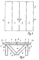
- the low drawingroom table comprises a bearing surface 1 formed by four upper rectangular, side by side arranged, flat elements 2, 3, 4, 5 which are equal to one another and overlap two lower rectangular, side by side arranged, flat elements 6 and 7 which are equal to each other and have the same length as the upper flat elements 2 to 5 while being each twice the width of one of them.
- the upper flat element 2 and the upper flat element 5 are connected by hinges 8 placed along the outer longer sides designated by numerals 2 a and 5 a to the corresponding outer longer sides of the lower flat elements 6 and 7, respectively.
- the inner longer sides of the upper flat elements 3 and 4 designated by numerals 3 b and 4 b are connected by hinges 8 to the corresponding inner longer sides of the two lower flat elements 6 and 7.
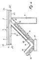
- the assembly of flat elements is supported by a pair of essentially M-shaped bearing members each comprising two vertical legs 9 integral with two slanting braces 10 and 11 forming a "V" the apex of which rests preferably but not necessarily on the floor through a base 12.
- Both slanting braces 10 and 11 are inside provided with a groove acting as an inner guide 13 eccentrically placed into the portion inwardly facing the "V" and leading at its upper end to a widened portion 15 having a shaped bottom 16 for example in the form of a step or the like.
- the lower end 18 of said arm 17 is complementary shaped as the bottom 16 of the widened portion 15 of the inner guide 13, while the upper end thereof ends in a horizontal bracket 19 integral with the lower surface of the lower flat elements 6 and 7.
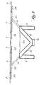
- Pairs of stiffening members 20, 21 are provided under the lower flat elements 6 and 7 and are placed crosswise to the flat elements and aligned to each other, for example in a number of three as shown in Figure 3.
- Said stiffening members are provided inside with supporting extension means 22, 22' and 23, 23' respectively which can be telescopically extended in opposite directions for supporting the upper flat elements 2 to 5 when the latter are suitably turned over about the respective hinges 8 thus providing a bearing surface which is solid, steady and safe.
- the invention provides according to a variant not shown that the horizontal brackets 19 supporting the bearing surface 1 are suitably hollow to contain the supporting means telescopically extensible in opposite directions.
- Stiffening cross-arms 24 parallel to the sides of the table are provided according to the invention between the slanting braces 10, 11 and between the M-shaped members.
- the portion of bearing surface 1 formed, for example, by the upper flat elements 4 and 5 overlapping the lower flat element 7 is raised till each supporting arm 17 sliding into the inner guide 13 of the respective slanting brace 11 reaches the widened portion 15 and moves towards the solid portion of the slanting brace 11 itself so that its shaped lower end 18 engages with the corresponding shaped bottom 16 of said widened portion 15.
- Each arm 17 is thus locked in the raised position in that it neither can shift downwards because of the engagement of the shapings 16 and 18 with each other nor turn over outwards because of the bearing contact against the lower wall of the widened portion 15 sustained by the corresponding vertical leg 9.
- the length of the arms 17 will be such that the sliding of the arms themselves upwards in the oblique direction allowing the lower flat element 7 and the overlapped upper flat elements 4, 5 to be raised causes a lateral shift of said flat elements outwards to an extent corresponding to the width of an upper flat element.
- the supporting extension means 23, 23' are then telescopically drawn out in opposite directions.
- the stiffening means 21 containing said extension means are placed under as well as crosswise to the lower flat element 7 along the middle axis thereof and outside the legs 9.
- the upper flat elements 4 and 5 are then turned over about the respective hinges 8 connecting them with the lower flat element 7 till they come into contact with the telescopic extension means 23, 23' so that said flat elements 4 and 5 are aligned with the flat element 7 to form a half raised and widened table.
- a sole widened surface raised at a suitable height from the floor is provided to be used in spread out position for example as a dining table.
- a low drawing-room table with widened surface and raised central portion is provided if only the two upper flat elements 2 and 5 are turned over.
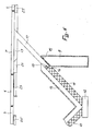
- An ornamental table with two surfaces at different levels is provided if only one lower flat element, for example that designated by 7, is raised without turning over the respective upper flat elements 4 and 5. If the upper inner flat element 4 is further turned over, a writing-desk with associated seat is provided, the bearing surface being further extensible by turning over the upper flat element 5.
- the flat elements can be, for example, square and the upper flat elements can also have different widths from each other and be in a number other than four provided that the whole surface of the upper flat elements is equal to the whole surface of the lower flat elements and that the lower flat elements are moved away from each other because of the inclined raising of the sliding arms to an extent equal to the width of the upper inner flat elements to be turned over.
- the M-shaped bearing members can assume a different form provided that they are equipped with the slanting braces forming a "V" and comprising the respective inner sliding arms.
- the members supporting the bearing surface can be formed by simple V-shaped members the apexes of which are suitably connected to assure the stability by means of a perimetrical basis, or the V-shaped slanting braces can be built in or covered by panels connected to one another to provide a box-like member supporting the bearing surface.
- the table could be formed by only one lower flat element to which upper flat elements that can be overturned are overlapped.
- Such an assembly is supported at each of the opposite ends by an inclined brace provided with the respective sliding arm and resting on the floor, for stability reasons, by means of a suitable ballasted base, thus giving rise to a low drawing-room table with reduced dimensions and bearing surface, which can be raised and widened to provide, for example, a dining table.
Landscapes
- Tables And Desks Characterized By Structural Shape (AREA)
- Combinations Of Kitchen Furniture (AREA)
Claims (14)
- Veränderbarer, niedriger Wohnzimmertisch umfassend eine Tragfläche (1), die von vier oberen, flachen, Seite an Seite angeordneten Elementen (2 bis 5) gebildet wird, die einander gleich sind, Trägereinrichtungen umfassend zentrale schräge Streben (10, 11), wobei jede schräge Strebe innen mit einer Führung (13) ausgestattet ist, mit der Funktion einen Gleitarm (17) zu führen, der am oberen Ende integral mit einem horizontalen Träger (19) verbunden ist, der die Tragfläche (1) trägt, wobei Einrichtungen vorhanden sind, um jeden Arm (17) in gehobener Position festzustellen, dadurch gekennzeichnet, daß die vier oberen flachen Elemente (2 bis 5) rechteckig sind und in der gleichen Richtung zwei untere, flache, rechteckige, Seite an Seite angeordnete Elemente (6, 7) überdecken, die einander gleich sind und die gleiche Länge haben wie die oberen flachen Elemente (2 bis 5), während jedes doppelt so breit ist wie eines von ihnen, wobei die oberen äußeren flachen Elemente (2,5) mit den unteren flachen Elementen (6, 7) an den entsprechenden äußeren längeren Seiten (2a, 5a) gelenkig verbunden sind und die oberen inneren flachen Elemente (3, 4) mit den unteren flachen Elementen (6, 7) an den entsprechenden inneren längeren Seiten (3b, 4b) gelenkig verbunden sind, wobei die Tragfläche (1) von einem Paar im wesentlichen M-förmigen Stützeinrichtungen getragen wird, wobei jede zwei äußere, vertikale Beine (9) hat, die integral mit den zwei zentralen, schrägen Streben (10, 11) die miteinander ein "V" bilden, verbunden sind und die Länge des Armes (17) derart ist, daß die Bewegung des letzteren in geneigter Richtung, wenn der Arm (17) festgestellt ist, eine seitliche Verschiebung der flachen Elemente, die von dem Arm außen gestützt werden, in Bezug auf den Tisch bewirkt, in einem Ausmaß, das der Breite eines oberen flachen Elementes entspricht.
- Tisch nach Anspruch 1, dadurch gekennzeichnet, daß jede innere Führung (13) der schrägen Streben (10, 11) exzentrisch angeordnet ist in dem Strebenteil, das im "V" nach innen gerichtet ist, und oben und nahe dem entsprechenden vertikalen Bein (9) mit einem geweiteten Teil (15) mit geformter Unterseite (16) ausgestattet ist, während das untere Ende (18) des Gleitarmes (17) mit einem Teil ausgestattet ist, das eine Form, die zu der Unterseite (16) des geweiteten Teiles (15) komplementär ist, hat, so daß sie, bei wechselseitigem Eingriff, die Mittel darstellen, die jeden Arm in der gehobenen Position feststellen.
- Tisch nach Anspruch 2, dadurch gekennzeichnet, das die komplementären Formen des Armes (17) und der Unterseite (16) des geweiteten Teiles (15) der inneren Führung (13) der schrägen Streben (10, 11) die Form einer Treppe haben.
- Tisch nach einem der Ansprüche 1 bis 3, dadurch gekennzeichnet, daß Versteifungseinrichtungen (20, 21) umfassend Teleskop-Verlängerungseinrichtungen (22, 22' und 23, 23') unter und quer zu den unteren flachen Elementen (6, 7) vorgesehen sind, wobei die Verlängerungseinrichtungen (22, 22' und 23, 23') in entgegengesetzten Richtungen verlängerbar sind und die oberen flachen Elemente (2 bis 5) tragen, wenn diese über die entsprechenden Gelenke (8), die sie mit den unteren flachen Elementen (6, 7) verbinden, umgeklappt werden.
- Tisch nach einem der Ansprüche 1 bis 3, dadurch gekennzeichnet, daß die horizontalen Träger (19), die die Tragfläche des Tisches tragen, die integral mit dem oberen Ende der Arme (17) verbunden sind, die in die schrägen Streben (10, 11) einschiebbar sind, hohl sind, so daß sie Vorrichtungen enthalten, die teleskopartig in entgegengesetzte Richtungen verlängert werden können um die oberen, flachen Elemente, wenn diese über die entsprechenden Gelenke, die sie mit den unteren flachen Elementen verbinden, umgeklappt werden, tragen zu können.
- Tisch nach einem der vorstehenden Ansprüche, dadurch gekennzeichnet, daß bekannte Vorrichtungen wie Riegel, Haken oder ähnliches vorgesehen sind um die oberen inneren flachen Elemente (3, 4) in umgeklappter Position miteinander zu verbinden, um die geöffnete Tragfläche (1) stabiler zu machen.
- Tisch nach einem der vorstehenden Ansprüche, dadurch gekennzeichnet, daß das Paar Glieder, die die Tragfläche tragen und im wesentlichen M-förmig sind, durch ein Paar anderer Stützglieder ersetzt wird, das jeweils die V-förmige schräge Strebe (10, 11) mit dem entsprechenden Gleitarm (17) einschließt.
- Tisch nach Anspruch 7, dadurch gekennzeichnet, daß die Stützglieder aus einem Paar V-förmiger schräger Streben bestehen, deren Scheitelpunkte mit einem Grundtragerahmen verbunden sind.
- Tisch nach Anspruch 7, dadurch gekennzeichnet, daß die Stützglieder aus Paneelen bestehen, die das Paar V-förmige schräge Streben enthalten oder verkleiden und miteinander zu einem kastenähnlichen Unterbau verbunden sind.
- Tisch nach Anspruch 4, dadurch gekennzeichnet, daß er in einen hohen Tisch, zum Beispiel einen Eßtisch, durch folgende Maßnahmen verändert werden kann:- Erhöhen eines der beiden unteren flachen Elemente (7) und der entsprechenden oberen flachen Elemente (4, 5), die darübergeklappt sind, und dadurch die entsprechenden Stützarme (17) in den inneren Führungen (13) der schrägen Streben (11) gleiten lassen, bis die Arme (17) durch die Sperreinrichtungen gehalten werden;- Ausziehen der teleskopartigen Stützverlängerungsvorrichtungen (23, 23') aus den Versteifungsvorrichtungen (21);- Umklappen der oberen flachen Elemente (4, 5) um die entsprechenden Gelenkverbindungen (8) bis sie mit den teleskopartigen Stützverlängerungsvorrichtungen (23, 23') in Kontakt kommen;- Erhöhen des anderen unteren flachen Elements (6) und Wiederholen der bereits beschriebenen Schritte um somit einen festen und sicheren Tisch mit einer erhöhten und verbreiterten Tragfläche bilden.
- Tisch nach Anspruch 4, dadurch gekennzeichnet, daß er veränderbar ist in einen niedrigen Wohnzimmertisch mit verbreiterter Tragfläche und einer erhöhten Zentraloberfläche durch Umklappen der zwei oberen äußeren flachen Elemente (2, 5).
- Tisch nach Anspruch 4, dadurch gekennzeichnet, daß er veränderbar ist in ein Möbelstück mit zwei Tragflächen auf unterschiedlichem Niveau durch Erhöhen von nur einer Hälfte des Tisches.
- Tisch nach Anspruch 4, dadurch gekennzeichnet, daß er veränderbar ist in einen Schreibtisch mit angeschlossenem Sitz durch Erhöhen von nur einer Hälfte des Tisches und durch Umklappen des oberen inneren flachen Elementes der erhöhten Tischhälfte, wobei die Tragfläche eines solchen Schreibtisches vergrößerbar ist durch Umklappen des oberen äußeren flachen Elementes dieser erhöhten Tischhälfte.
- Tisch nach Anspruch 4, dadurch gekennzeichnet, daß er aus einem einzelnen unteren flachen Element besteht, das von oberen flachen Elementen, die umgeklappt werden können, überdeckt wird und das an beiden gegenüberliegenden äußeren Enden durch schräge Streben mit entsprechenden Gleitarmen getragen wird, wobei die schrägen Streben auf dem Boden mit Hilfe einer geeigneten beschwerten Basis ruhen und so einen niedrigen kleinen Wohnzimmertisch bilden, der erhöht und vergrößert werden kann, um zum Beispiel einen Eßzimmertisch zu bilden.
Applications Claiming Priority (2)
| Application Number | Priority Date | Filing Date | Title |
|---|---|---|---|
| IT4767485 | 1985-02-13 | ||
| IT47674/85A IT1221494B (it) | 1985-02-13 | 1985-02-13 | Tavolino da salotto trasformabile |
Publications (3)
| Publication Number | Publication Date |
|---|---|
| EP0208656A2 EP0208656A2 (de) | 1987-01-14 |
| EP0208656A3 EP0208656A3 (en) | 1988-02-03 |
| EP0208656B1 true EP0208656B1 (de) | 1991-10-02 |
Family
ID=11261820
Family Applications (1)
| Application Number | Title | Priority Date | Filing Date |
|---|---|---|---|
| EP86830030A Expired EP0208656B1 (de) | 1985-02-13 | 1986-02-12 | Verwandelbarer niedriger Salontisch |
Country Status (4)
| Country | Link |
|---|---|
| US (1) | US4677919A (de) |
| EP (1) | EP0208656B1 (de) |
| DE (1) | DE3681761D1 (de) |
| IT (1) | IT1221494B (de) |
Families Citing this family (8)
| Publication number | Priority date | Publication date | Assignee | Title |
|---|---|---|---|---|
| DE3920432C2 (de) * | 1989-06-22 | 1997-10-02 | Krause Robert Gmbh Co Kg | Höhenverstellbarer Stützfuß für Möbel, wie Klapptische, Platten in Wohnwagen |
| US4949650A (en) * | 1989-07-31 | 1990-08-21 | Allard David D | Table having a part of which is adjustable upwardly |
| DE4209323A1 (de) * | 1992-03-22 | 1993-09-23 | Markus Harm | Vorrichtung zur hoehenverstellung insbesondere bei tischen |
| US5503086A (en) * | 1993-03-19 | 1996-04-02 | Ultra-Mek, Inc. | Table with movable top surface |
| US5460104A (en) * | 1994-02-14 | 1995-10-24 | Young, Sr.; James | Stowable table |
| MY128770A (en) * | 2001-11-23 | 2007-02-28 | Green Continental Furniture M Sdn Bhd | A sofa table with adjustable height |
| US20070163475A1 (en) * | 2006-01-17 | 2007-07-19 | Murphy Marcus L | Table with movable top surface and mechanism for same |
| CN102777744A (zh) * | 2012-07-31 | 2012-11-14 | 苏州傲海精密钣金制造有限公司 | 电视机架座 |
Family Cites Families (13)
| Publication number | Priority date | Publication date | Assignee | Title |
|---|---|---|---|---|
| US236589A (en) * | 1881-01-11 | Library double-top extension-table | ||
| US529140A (en) * | 1894-11-13 | sghnaee | ||
| US1009034A (en) * | 1910-08-30 | 1911-11-21 | George Arndt | Extension-table. |
| US1167905A (en) * | 1915-07-07 | 1916-01-11 | Michael Kreczkowski | Extension-table. |
| US1197172A (en) * | 1915-10-05 | 1916-09-05 | Giovanni Baldi | Table. |
| GB489491A (en) * | 1937-10-15 | 1938-07-28 | Louis Harris Lebus | Improvements in or relating to extending tables |
| US2599020A (en) * | 1951-05-31 | 1952-06-03 | Alden L Safstrom | Vertically adjustable table |
| US2666680A (en) * | 1953-03-16 | 1954-01-19 | Alperstein Harry | Extendable table with foldable leaves |
| US2852325A (en) * | 1957-09-20 | 1958-09-16 | Dunbar Furniture Corp Of India | Extension table |
| US3179071A (en) * | 1963-06-24 | 1965-04-20 | Dale G Johnston | Adjustable table structure |
| FR1475283A (fr) * | 1966-04-08 | 1967-03-31 | Table réglable en hauteur et en largeur | |
| DE2644668C2 (de) * | 1976-10-02 | 1983-11-17 | Ferdinand 5000 Köln Schumacher | Ausziehtisch |
| EP0074019A3 (de) * | 1981-09-04 | 1985-11-06 | Asea Ab | Überwachungspult |
-
1985
- 1985-02-13 IT IT47674/85A patent/IT1221494B/it active
-
1986
- 1986-02-04 US US06/825,931 patent/US4677919A/en not_active Expired - Fee Related
- 1986-02-12 DE DE8686830030T patent/DE3681761D1/de not_active Expired - Lifetime
- 1986-02-12 EP EP86830030A patent/EP0208656B1/de not_active Expired
Also Published As
| Publication number | Publication date |
|---|---|
| US4677919A (en) | 1987-07-07 |
| EP0208656A2 (de) | 1987-01-14 |
| DE3681761D1 (de) | 1991-11-07 |
| EP0208656A3 (en) | 1988-02-03 |
| IT1221494B (it) | 1990-07-06 |
| IT8547674A0 (it) | 1985-02-13 |
Similar Documents
| Publication | Publication Date | Title |
|---|---|---|
| US3921539A (en) | Shelf support structure | |
| US4313385A (en) | Folding furniture | |
| US4400031A (en) | Interlocking chair | |
| EP0723409B1 (de) | Klapptisch | |
| US4974526A (en) | Portable self-storing folding table | |
| US2748954A (en) | Shelving | |
| US3861325A (en) | Convertible folding table-carrel unit | |
| CA2007900A1 (en) | Collapsible container | |
| US5275579A (en) | Aerobic climbing step/bench | |
| US3845728A (en) | Folding table | |
| EP0966216B1 (de) | Zusammenklappbarer tisch | |
| EP0208656B1 (de) | Verwandelbarer niedriger Salontisch | |
| KR940702244A (ko) | 다단계 절첩식 스테이지(Multi-level folding stage) | |
| US6968789B2 (en) | Folding table with central support assembly | |
| US3113533A (en) | Locking and unlocking folding brace | |
| JPH05253041A (ja) | モジュール式棚 | |
| CA1229213A (en) | Universal telescopic stretcher rail system | |
| US2707664A (en) | Folding legs for collapsible table | |
| US5405020A (en) | Adjustable hanging file frame system | |
| US5035335A (en) | Stackable and nestible backs | |
| CA1212030A (en) | Knockdown picnic table | |
| US4366585A (en) | Armchair effective to be transformed into a bed | |
| KR100543899B1 (ko) | 3단-높이 접이식 스테이지 | |
| US3163296A (en) | Collapsible rack | |
| US3204778A (en) | Folding tray construction |
Legal Events
| Date | Code | Title | Description |
|---|---|---|---|
| PUAI | Public reference made under article 153(3) epc to a published international application that has entered the european phase |
Free format text: ORIGINAL CODE: 0009012 |
|
| AK | Designated contracting states |
Kind code of ref document: A2 Designated state(s): BE CH DE FR GB LI NL |
|
| PUAL | Search report despatched |
Free format text: ORIGINAL CODE: 0009013 |
|
| AK | Designated contracting states |
Kind code of ref document: A3 Designated state(s): BE CH DE FR GB LI NL |
|
| 17P | Request for examination filed |
Effective date: 19880729 |
|
| 17Q | First examination report despatched |
Effective date: 19900105 |
|
| GRAA | (expected) grant |
Free format text: ORIGINAL CODE: 0009210 |
|
| AK | Designated contracting states |
Kind code of ref document: B1 Designated state(s): BE CH DE FR GB LI NL |
|
| REF | Corresponds to: |
Ref document number: 3681761 Country of ref document: DE Date of ref document: 19911107 |
|
| ET | Fr: translation filed | ||
| PLBE | No opposition filed within time limit |
Free format text: ORIGINAL CODE: 0009261 |
|
| STAA | Information on the status of an ep patent application or granted ep patent |
Free format text: STATUS: NO OPPOSITION FILED WITHIN TIME LIMIT |
|
| 26N | No opposition filed | ||
| PGFP | Annual fee paid to national office [announced via postgrant information from national office to epo] |
Ref country code: NL Payment date: 19940228 Year of fee payment: 9 |
|
| PGFP | Annual fee paid to national office [announced via postgrant information from national office to epo] |
Ref country code: CH Payment date: 19940531 Year of fee payment: 9 |
|
| PGFP | Annual fee paid to national office [announced via postgrant information from national office to epo] |
Ref country code: GB Payment date: 19940603 Year of fee payment: 9 |
|
| PGFP | Annual fee paid to national office [announced via postgrant information from national office to epo] |
Ref country code: FR Payment date: 19940615 Year of fee payment: 9 |
|
| PGFP | Annual fee paid to national office [announced via postgrant information from national office to epo] |
Ref country code: DE Payment date: 19940629 Year of fee payment: 9 |
|
| PGFP | Annual fee paid to national office [announced via postgrant information from national office to epo] |
Ref country code: BE Payment date: 19940713 Year of fee payment: 9 |
|
| PG25 | Lapsed in a contracting state [announced via postgrant information from national office to epo] |
Ref country code: GB Effective date: 19950212 |
|
| PG25 | Lapsed in a contracting state [announced via postgrant information from national office to epo] |
Ref country code: LI Effective date: 19950228 Ref country code: CH Effective date: 19950228 Ref country code: BE Effective date: 19950228 |
|
| BERE | Be: lapsed |
Owner name: BAGGIANI GIUSEPPE Effective date: 19950228 |
|
| PG25 | Lapsed in a contracting state [announced via postgrant information from national office to epo] |
Ref country code: NL Effective date: 19950901 |
|
| GBPC | Gb: european patent ceased through non-payment of renewal fee |
Effective date: 19950212 |
|
| PG25 | Lapsed in a contracting state [announced via postgrant information from national office to epo] |
Ref country code: FR Effective date: 19951031 |
|
| NLV4 | Nl: lapsed or anulled due to non-payment of the annual fee |
Effective date: 19950901 |
|
| PG25 | Lapsed in a contracting state [announced via postgrant information from national office to epo] |
Ref country code: DE Effective date: 19951101 |
|
| REG | Reference to a national code |
Ref country code: FR Ref legal event code: ST |