EP0208616B1 - Dispositif de butée élastique amortie - Google Patents
Dispositif de butée élastique amortie Download PDFInfo
- Publication number
- EP0208616B1 EP0208616B1 EP86401487A EP86401487A EP0208616B1 EP 0208616 B1 EP0208616 B1 EP 0208616B1 EP 86401487 A EP86401487 A EP 86401487A EP 86401487 A EP86401487 A EP 86401487A EP 0208616 B1 EP0208616 B1 EP 0208616B1
- Authority
- EP
- European Patent Office
- Prior art keywords
- fact
- yarn
- loops
- loop
- boss
- Prior art date
- Legal status (The legal status is an assumption and is not a legal conclusion. Google has not performed a legal analysis and makes no representation as to the accuracy of the status listed.)
- Expired - Lifetime
Links
- 238000013016 damping Methods 0.000 title claims description 7
- 238000006073 displacement reaction Methods 0.000 claims description 7
- 238000006243 chemical reaction Methods 0.000 claims description 6
- 239000000463 material Substances 0.000 claims description 6
- 230000002093 peripheral effect Effects 0.000 claims description 6
- 230000000750 progressive effect Effects 0.000 claims description 5
- 239000004952 Polyamide Substances 0.000 claims description 4
- 239000004760 aramid Substances 0.000 claims description 4
- 229920003235 aromatic polyamide Polymers 0.000 claims description 4
- 229920002647 polyamide Polymers 0.000 claims description 4
- 239000000470 constituent Substances 0.000 claims description 3
- 239000000835 fiber Substances 0.000 claims description 3
- 229920005989 resin Polymers 0.000 claims description 3
- 239000011347 resin Substances 0.000 claims description 3
- 230000000694 effects Effects 0.000 description 3
- 229920000271 Kevlar® Polymers 0.000 description 2
- 239000004677 Nylon Substances 0.000 description 2
- 239000004761 kevlar Substances 0.000 description 2
- 229920001778 nylon Polymers 0.000 description 2
- 230000002159 abnormal effect Effects 0.000 description 1
- 239000006096 absorbing agent Substances 0.000 description 1
- 229920002457 flexible plastic Polymers 0.000 description 1
- 239000002184 metal Substances 0.000 description 1
- 230000007935 neutral effect Effects 0.000 description 1
- 230000010355 oscillation Effects 0.000 description 1
- 230000000737 periodic effect Effects 0.000 description 1
- 239000004033 plastic Substances 0.000 description 1
- 229920003023 plastic Polymers 0.000 description 1
- 230000001681 protective effect Effects 0.000 description 1
- 239000005060 rubber Substances 0.000 description 1
- 230000035939 shock Effects 0.000 description 1
- 230000001502 supplementing effect Effects 0.000 description 1
- 239000000725 suspension Substances 0.000 description 1
- 229920003002 synthetic resin Polymers 0.000 description 1
- 239000000057 synthetic resin Substances 0.000 description 1
- 229920001169 thermoplastic Polymers 0.000 description 1
- 239000004416 thermosoftening plastic Substances 0.000 description 1
Images
Classifications
-
- F—MECHANICAL ENGINEERING; LIGHTING; HEATING; WEAPONS; BLASTING
- F16—ENGINEERING ELEMENTS AND UNITS; GENERAL MEASURES FOR PRODUCING AND MAINTAINING EFFECTIVE FUNCTIONING OF MACHINES OR INSTALLATIONS; THERMAL INSULATION IN GENERAL
- F16F—SPRINGS; SHOCK-ABSORBERS; MEANS FOR DAMPING VIBRATION
- F16F7/00—Vibration-dampers; Shock-absorbers
- F16F7/14—Vibration-dampers; Shock-absorbers of cable support type, i.e. frictionally-engaged loop-forming cables
-
- F—MECHANICAL ENGINEERING; LIGHTING; HEATING; WEAPONS; BLASTING
- F16—ENGINEERING ELEMENTS AND UNITS; GENERAL MEASURES FOR PRODUCING AND MAINTAINING EFFECTIVE FUNCTIONING OF MACHINES OR INSTALLATIONS; THERMAL INSULATION IN GENERAL
- F16F—SPRINGS; SHOCK-ABSORBERS; MEANS FOR DAMPING VIBRATION
- F16F1/00—Springs
- F16F1/36—Springs made of rubber or other material having high internal friction, e.g. thermoplastic elastomers
- F16F1/366—Springs made of rubber or other material having high internal friction, e.g. thermoplastic elastomers made of fibre-reinforced plastics, i.e. characterised by their special construction from such materials
-
- F—MECHANICAL ENGINEERING; LIGHTING; HEATING; WEAPONS; BLASTING
- F16—ENGINEERING ELEMENTS AND UNITS; GENERAL MEASURES FOR PRODUCING AND MAINTAINING EFFECTIVE FUNCTIONING OF MACHINES OR INSTALLATIONS; THERMAL INSULATION IN GENERAL
- F16F—SPRINGS; SHOCK-ABSORBERS; MEANS FOR DAMPING VIBRATION
- F16F1/00—Springs
- F16F1/36—Springs made of rubber or other material having high internal friction, e.g. thermoplastic elastomers
- F16F1/42—Springs made of rubber or other material having high internal friction, e.g. thermoplastic elastomers characterised by the mode of stressing
- F16F1/46—Springs made of rubber or other material having high internal friction, e.g. thermoplastic elastomers characterised by the mode of stressing loaded mainly in tension
-
- F—MECHANICAL ENGINEERING; LIGHTING; HEATING; WEAPONS; BLASTING
- F16—ENGINEERING ELEMENTS AND UNITS; GENERAL MEASURES FOR PRODUCING AND MAINTAINING EFFECTIVE FUNCTIONING OF MACHINES OR INSTALLATIONS; THERMAL INSULATION IN GENERAL
- F16F—SPRINGS; SHOCK-ABSORBERS; MEANS FOR DAMPING VIBRATION
- F16F2236/00—Mode of stressing of basic spring or damper elements or devices incorporating such elements
- F16F2236/06—Tension
Definitions
- the present invention relates to a damped elastic stop device, constituting a self-damping spring which has progressive mechanical reactions corresponding to the algebraic sum of elastic reactions and friction, this device being capable of controlling the relative displacements of two moving parts one with respect to the other in a determined direction.
- a device of this kind is known from document DE-A 3 014 593.
- thermoplastics non-metallic
- polyamide or aramid resins in the form of wires or cables, which offer remarkable properties of mechanical resistance and elasticity, and are therefore likely, for a small mass of material, to accumulate and restore a large amount of mechanical energy, provided that this energy is provided in the form of tensile forces for a period all the more brief as the stress is higher .
- the invention aims to take advantage of the existence of these materials to achieve very light elastic stops, by adopting arrangements which make it possible to dissipate, in the form of heat resulting from friction, a large part of the mechanical energy absorbed .
- the present invention thus relates to a damped elastic stop device which comprises two identical wire loops contained in planes parallel to the direction of relative movement of the two aforementioned parts, these planes being very close together or merged into one and the same plane, and arranged symmetrically by relative to an axis parallel to said direction; the wire of each loop, attached by its ends to one of the moving parts, passes around a button attached to the other part on which it can slide with friction, while said wire is made of a material offering great mechanical tensile strength and considerable elastic elongation capacity, preferably made of synthetic polyamide or aramid resin fibers ("Nylon”, "Kevlar”, etc.), and that the constituent elements of the device are geometrically dimensioned so that , when the moving parts move from a relative rest position, the wire of each loop undergoes progressive elongation, and the part of the wire in contact, direct or indirect, with the button, slides on the peripheral surface of this one.
- wire is understood here to mean both a single-stranded wire (monofilament) and a wire stranded with several strands, or cable.
- the constituent elements of the device according to the invention should be geometrically dimensioned so that, when the moving parts move from a relative rest position, the wire of each loop undergoes progressive elongation, and that the part of the wire in contact, direct or indirect, with the button, slides on the peripheral surface of it.
- each badge has a circular peripheral contour, this preferably comprising a groove which receives the wire from the corresponding loop.
- the wire of each loop can be, at least in its middle portion in contact with the button, coated with a friction sheath which protects it from rapid wear.
- Each loop is advantageously provided with a device for adjusting the tension of the thread, making it possible to measure the degree of initial prestressing thereof.
- the attachment ends of the loops can be closer to the above-mentioned axis of symmetry than the buttons.
- said ends are further from the axis of symmetry than the buttons.
- the latter are then preferably superimposed, their contours coinciding at least approximately.
- the two superimposed buttons can constitute a single disc comprising for the two loops two respective circular grooves arranged side by side and centered on the axis of the disc.
- a device according to the invention as defined above constitutes a damped elastic stop, with double effect, capable of authorizing and limiting the relative displacements of two mechanical parts, in the two directions of a determined direction.
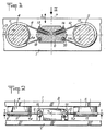
- two parts 1, 2 may move relative to each other in a direction of translation 3 determined.
- To the piece 1 are fixed two identical metallic macaroons 4, 5, offering at their periphery circular grooves 4a, 5a of the same diameter, which are located in the same plane 6 parallel to the direction 3, symmetrically with respect to an axis 7 parallel to this direction and contained in said plane.
- To the part 2 is fixed a block 8 arranged between the buttons 4, 5, at equal distance from these.
- the block 8 is connected to each of the buttons 4, 5 by a loop of wire 9, 10 respectively, the ends of which are attached to said block and which surrounds the corresponding button passing through the peripheral groove thereof, with which it is in contact by means of a friction sheath 11, 12.
- the two loops are located in the plane 6, symmetrically with respect to the axis 7.
- Each is, at one end 19, 20, simply anchored in the block 8 and , at its other end, attached to the latter by a device 13, 14 making it possible to adjust its length and its tension at rest.
- the loops 9, 10 are made using wire or cable made of synthetic resin fibers of the polyamide or aramid type, such as "Nylon” or “Kevlar", capable of withstanding great mechanical stresses in traction, with elongation considerable elasticity and without appreciable permanent deformation if the effort is of short duration.
- the protective sheaths 11, 12 can be made of flexible plastic or of rubber material.
- the grooves 4a, 5a should, as shown, have a transverse profile in the form of an arc of a circle, so as to contain exactly the respective sheaths 11, 12 for protecting the wires forming the loops 9, 10.
- the four rectilinear branches of the two loops, 9, 10 are subjected to equal forces, possibly weak or even zero, resulting from the initial tension adjustment.
- an external force causes the displacement of the part 2 downwards compared to the part 1 (according to the representation of figure 1), the total length of each loop increases, the length of the two upper branches increasing more quickly than the length of the two lower branches is reduced. This imposes a sliding of the sheathed middle part of each loop in the corresponding groove 4a, 5a of the buttons 4, 5.
- the forces exerted on the upper branches, on the one hand, and the forces exerted on the lower branches, on the other hand, are composed to create an overall resulting force which opposes the downward movement of the part 2.
- This resulting force increases with the stroke in a very gradual manner, the unit elastic reaction being substantially zero at the start to become very significant when the total length of each loop increases sharply, as the displacement separates the two mechanical parts 1 and 2 from their original position.
- the friction forces in the grooves 4a, 5a also increase with the traction forces exerted on the branches of the loops, but their result is added to the elastic forces when the parts 1, 2 move away from each other, while it opposes the elastic forces when said parts approach. This results in a damping effect, adjustable by the choice of the initial tension, which very quickly reduces the amplitude of the periodic oscillations caused by the elastic reactions exerted between the parts 1, 2.
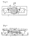
- the grooves 4a, 5a for receiving the loops 9, 10 are grouped side by side on the same disc 45 fixed to the part 2, while two blocks 18, 28 are fixed to the piece 1 symmetrically on either side of the disc 45.
- the wire loop 9 passes over the groove 4a and its ends are attached to the block 18, while the loop 10 passes over the groove 5a, its ends being attached to the other block 28.
- Said loops are here also provided with tension adjustment devices 13, 14.
- the arrangement is always symmetrical with respect to the axis 7, with this only difference, without consequence in practical, that the wire loops are no longer in the same plane 6, but, as shown in FIG. 4, in two very close parallel planes, located on either side of the axis 7.
- This latter device operates in exactly the same way as the device in FIGS. 1 and 2.
- the described devices having, in their initial rest position shown, a symmetry also with respect to an axis 17 parallel to the flat flanges and perpendicular to the direction 3 of movement of the parts 1, 2, it is clear that they are capable of damping, then limiting by stop effect the displacements of said parts both in one direction than in the opposite direction, and in the same way. They are therefore double-acting devices, so each, apart from its damping properties, is equivalent to a pair of conventional limit stops. It also appears that these same devices ensure relative positioning along the axis 17 of the parts 1, 2 with which they are associated.
- double-acting damped stop devices is particularly advantageous for supplementing the suspension of land vehicles, by limiting the travel of the wheels relative to the hull, by ensuring the lateral or longitudinal positioning of the hull relative to the mechanical parts. not suspended, and possibly replacing the shock absorbers generally inserted between the suspended part and the unsprung part of the vehicle.
Landscapes
- Engineering & Computer Science (AREA)
- General Engineering & Computer Science (AREA)
- Mechanical Engineering (AREA)
- Health & Medical Sciences (AREA)
- Child & Adolescent Psychology (AREA)
- Vibration Dampers (AREA)
Applications Claiming Priority (2)
| Application Number | Priority Date | Filing Date | Title |
|---|---|---|---|
| FR8510357A FR2584467B1 (fr) | 1985-07-05 | 1985-07-05 | Dispositif de butee elastique amortie |
| FR8510357 | 1985-07-05 |
Publications (3)
| Publication Number | Publication Date |
|---|---|
| EP0208616A2 EP0208616A2 (fr) | 1987-01-14 |
| EP0208616A3 EP0208616A3 (en) | 1988-01-07 |
| EP0208616B1 true EP0208616B1 (fr) | 1990-08-01 |
Family
ID=9321028
Family Applications (1)
| Application Number | Title | Priority Date | Filing Date |
|---|---|---|---|
| EP86401487A Expired - Lifetime EP0208616B1 (fr) | 1985-07-05 | 1986-07-04 | Dispositif de butée élastique amortie |
Country Status (5)
| Country | Link |
|---|---|
| US (1) | US4725048A (enExample) |
| EP (1) | EP0208616B1 (enExample) |
| JP (1) | JPS6262031A (enExample) |
| DE (1) | DE3673091D1 (enExample) |
| FR (1) | FR2584467B1 (enExample) |
Families Citing this family (10)
| Publication number | Priority date | Publication date | Assignee | Title |
|---|---|---|---|---|
| FR2649769B1 (fr) * | 1989-07-11 | 1991-10-25 | Jarret Expl Ressorts Auto Amor | Dispositif amortisseur de roulis |
| ATE351945T1 (de) * | 1993-07-10 | 2007-02-15 | Baca Ltd | Elastisches seil |
| FR2707718B1 (fr) * | 1993-07-16 | 1995-09-01 | Bourbon Automobile Sa | Dispositif ralentisseur pour objet en mouvement. |
| NO316137B1 (no) * | 2002-03-14 | 2003-12-15 | Olav Kaarstein | Anordning for demping av vibrasjoner, stöt og sjokk |
| ES2251318B1 (es) * | 2004-10-15 | 2007-02-16 | Malla Talud Cantabria, S.L. | Dispositivo amortiguador de impactos en sistemas de proteccion de taludes. |
| JP4744307B2 (ja) * | 2006-01-19 | 2011-08-10 | 濱中ナット株式会社 | 機械的特性の付与構造 |
| JP5377874B2 (ja) * | 2008-03-27 | 2013-12-25 | 川田工業株式会社 | 制振部材及び構造物の制振構造 |
| RU2383796C1 (ru) * | 2008-11-05 | 2010-03-10 | Государственное образовательное учреждение высшего профессионального образования Военно-морская академия имени Адмирала Флота Советского Союза Н.Г. КУЗНЕЦОВА | Виброизолятор |
| US8258680B2 (en) * | 2009-11-09 | 2012-09-04 | General Electric Company | Key bar compression apparatus |
| CN105897775B (zh) * | 2010-12-23 | 2019-10-18 | 瑞典爱立信有限公司 | 用于将设备连接到通信网络的系统、方法、网络实体和设备 |
Family Cites Families (9)
| Publication number | Priority date | Publication date | Assignee | Title |
|---|---|---|---|---|
| CH144449A (fr) * | 1929-10-29 | 1930-12-31 | Hirtzlin Joseph | Dispositif amortisseur de secousses pour la suspension des châssis pour automobiles, camionnettes, etc. |
| US2854718A (en) * | 1954-12-01 | 1958-10-07 | Paolo A Viola | Clothesline tightener |
| US3031034A (en) * | 1959-07-13 | 1962-04-24 | Lord Mfg Co | Damper |
| US3034597A (en) * | 1960-11-14 | 1962-05-15 | Lord Mfg Co | Friction damper |
| US3596737A (en) * | 1969-07-10 | 1971-08-03 | Anacanda Wire And Cable Co | Braking apparatus |
| GB1479887A (en) * | 1973-06-05 | 1977-07-13 | Cementation Ltd | Resiliently supporting a body |
| JPS5424179Y2 (enExample) * | 1975-07-28 | 1979-08-16 | ||
| JPS588171B2 (ja) * | 1978-06-16 | 1983-02-15 | 株式会社日立製作所 | 遅延回路 |
| DE3014593C2 (de) * | 1980-04-16 | 1982-06-16 | Messerschmitt-Bölkow-Blohm GmbH, 8000 München | Dämpfungsarmes Lager |
-
1985
- 1985-07-05 FR FR8510357A patent/FR2584467B1/fr not_active Expired
-
1986
- 1986-07-01 US US06/880,883 patent/US4725048A/en not_active Expired - Fee Related
- 1986-07-04 EP EP86401487A patent/EP0208616B1/fr not_active Expired - Lifetime
- 1986-07-04 JP JP61156320A patent/JPS6262031A/ja active Granted
- 1986-07-04 DE DE8686401487T patent/DE3673091D1/de not_active Expired - Fee Related
Also Published As
| Publication number | Publication date |
|---|---|
| DE3673091D1 (de) | 1990-09-06 |
| EP0208616A2 (fr) | 1987-01-14 |
| FR2584467A1 (fr) | 1987-01-09 |
| US4725048A (en) | 1988-02-16 |
| JPH0427412B2 (enExample) | 1992-05-11 |
| JPS6262031A (ja) | 1987-03-18 |
| FR2584467B1 (fr) | 1988-12-02 |
| EP0208616A3 (en) | 1988-01-07 |
Similar Documents
| Publication | Publication Date | Title |
|---|---|---|
| EP0208616B1 (fr) | Dispositif de butée élastique amortie | |
| CA1296504C (fr) | Poteau en matiere plastique pour supporter notamment des lignes electriques et dispositif pour realiser un enroulement de fibres sur ce poteau | |
| EP0296974A1 (fr) | Supports élastiques | |
| FR2468035A1 (fr) | Amortisseur a friction, notamment pour machines a laver a essorage centrifuge | |
| EP0666967A1 (fr) | Dispositif amortisseur pour systeme mecanique. | |
| FR2538479A1 (fr) | Disque amortisseur pour disque d'embrayage a friction d'un vehicule, notamment automobile | |
| FR2596126A1 (fr) | Dispositif, notamment un volant divise, pour reduire les oscillations, engendrees du cote du moteur, dans une ligne de transmission | |
| FR2651547A1 (fr) | Embrayage a elasticite dans le sens de la rotation. | |
| EP2959193B1 (fr) | Verin a cables tolerant aux desalignements | |
| FR2832479A1 (fr) | Dispositif d'amortissement pour cable | |
| WO1998041284A1 (fr) | Sangle amortisseuse de securite | |
| FR2534385A1 (fr) | Cable optique a structure libre, notamment monovoie | |
| EP0161146B1 (fr) | Système de suspension pour un train de roues de véhicule à essieu rigide | |
| EP3100939A1 (fr) | Dispositif de reglage de tension d'une transmission a courroie, notamment pour une application a un velo | |
| FR2648086A1 (fr) | Structure de suspension de vehicule | |
| EP0504003B1 (fr) | Dispositif de rappel en un point central | |
| FR2716118A1 (fr) | Dispositif de freinage pour un article de sport, notamment un ski. | |
| EP0387135B1 (fr) | Dispositif de tension d'une courroie de transmission de puissance | |
| FR2649769A1 (fr) | Dispositif amortisseur de roulis | |
| FR2672653A1 (fr) | Commande antivibration a cable flexible. | |
| EP0819962B1 (fr) | Dispositif de suspension et de guidage en translation pour un appareil et appareil équipé d'un tel dispositif | |
| WO1998024956A1 (fr) | Dispositif amortisseur pour ressort de lisse de metier a tisser jacquard | |
| FR3014156A1 (fr) | Absorbeur d'energie pour siege anticrash et siege anticrash comportant un tel absorbeur d'energie | |
| FR2560952A1 (fr) | Amortisseur a ressort | |
| FR2612858A1 (fr) | Frein de cable pour l'entrainement d'un dispositif destine a retendre une ceinture de securite |
Legal Events
| Date | Code | Title | Description |
|---|---|---|---|
| PUAI | Public reference made under article 153(3) epc to a published international application that has entered the european phase |
Free format text: ORIGINAL CODE: 0009012 |
|
| AK | Designated contracting states |
Kind code of ref document: A2 Designated state(s): DE GB IT SE |
|
| PUAL | Search report despatched |
Free format text: ORIGINAL CODE: 0009013 |
|
| AK | Designated contracting states |
Kind code of ref document: A3 Designated state(s): DE GB IT SE |
|
| 17P | Request for examination filed |
Effective date: 19880630 |
|
| 17Q | First examination report despatched |
Effective date: 19890419 |
|
| GRAA | (expected) grant |
Free format text: ORIGINAL CODE: 0009210 |
|
| AK | Designated contracting states |
Kind code of ref document: B1 Designated state(s): DE GB IT SE |
|
| GBT | Gb: translation of ep patent filed (gb section 77(6)(a)/1977) | ||
| REF | Corresponds to: |
Ref document number: 3673091 Country of ref document: DE Date of ref document: 19900906 |
|
| ITF | It: translation for a ep patent filed | ||
| PLBE | No opposition filed within time limit |
Free format text: ORIGINAL CODE: 0009261 |
|
| STAA | Information on the status of an ep patent application or granted ep patent |
Free format text: STATUS: NO OPPOSITION FILED WITHIN TIME LIMIT |
|
| 26N | No opposition filed | ||
| ITTA | It: last paid annual fee | ||
| PGFP | Annual fee paid to national office [announced via postgrant information from national office to epo] |
Ref country code: GB Payment date: 19940628 Year of fee payment: 9 |
|
| PGFP | Annual fee paid to national office [announced via postgrant information from national office to epo] |
Ref country code: DE Payment date: 19940721 Year of fee payment: 9 |
|
| PGFP | Annual fee paid to national office [announced via postgrant information from national office to epo] |
Ref country code: SE Payment date: 19940731 Year of fee payment: 9 |
|
| EAL | Se: european patent in force in sweden |
Ref document number: 86401487.3 |
|
| PG25 | Lapsed in a contracting state [announced via postgrant information from national office to epo] |
Ref country code: GB Effective date: 19950704 |
|
| PG25 | Lapsed in a contracting state [announced via postgrant information from national office to epo] |
Ref country code: SE Effective date: 19950705 |
|
| GBPC | Gb: european patent ceased through non-payment of renewal fee |
Effective date: 19950704 |
|
| PG25 | Lapsed in a contracting state [announced via postgrant information from national office to epo] |
Ref country code: DE Effective date: 19960402 |
|
| EUG | Se: european patent has lapsed |
Ref document number: 86401487.3 |
|
| PG25 | Lapsed in a contracting state [announced via postgrant information from national office to epo] |
Ref country code: IT Free format text: LAPSE BECAUSE OF NON-PAYMENT OF DUE FEES;WARNING: LAPSES OF ITALIAN PATENTS WITH EFFECTIVE DATE BEFORE 2007 MAY HAVE OCCURRED AT ANY TIME BEFORE 2007. THE CORRECT EFFECTIVE DATE MAY BE DIFFERENT FROM THE ONE RECORDED. Effective date: 20050704 |