EP0208150A2 - Powder dosing apparatus - Google Patents
Powder dosing apparatus Download PDFInfo
- Publication number
- EP0208150A2 EP0208150A2 EP86107764A EP86107764A EP0208150A2 EP 0208150 A2 EP0208150 A2 EP 0208150A2 EP 86107764 A EP86107764 A EP 86107764A EP 86107764 A EP86107764 A EP 86107764A EP 0208150 A2 EP0208150 A2 EP 0208150A2
- Authority
- EP
- European Patent Office
- Prior art keywords
- powder
- flow
- container
- conical
- vessel
- Prior art date
- Legal status (The legal status is an assumption and is not a legal conclusion. Google has not performed a legal analysis and makes no representation as to the accuracy of the status listed.)
- Withdrawn
Links
Images


Classifications
-
- B—PERFORMING OPERATIONS; TRANSPORTING
- B05—SPRAYING OR ATOMISING IN GENERAL; APPLYING FLUENT MATERIALS TO SURFACES, IN GENERAL
- B05B—SPRAYING APPARATUS; ATOMISING APPARATUS; NOZZLES
- B05B7/00—Spraying apparatus for discharge of liquids or other fluent materials from two or more sources, e.g. of liquid and air, of powder and gas
- B05B7/14—Spraying apparatus for discharge of liquids or other fluent materials from two or more sources, e.g. of liquid and air, of powder and gas designed for spraying particulate materials
- B05B7/1404—Arrangements for supplying particulate material
- B05B7/144—Arrangements for supplying particulate material the means for supplying particulate material comprising moving mechanical means
-
- C—CHEMISTRY; METALLURGY
- C23—COATING METALLIC MATERIAL; COATING MATERIAL WITH METALLIC MATERIAL; CHEMICAL SURFACE TREATMENT; DIFFUSION TREATMENT OF METALLIC MATERIAL; COATING BY VACUUM EVAPORATION, BY SPUTTERING, BY ION IMPLANTATION OR BY CHEMICAL VAPOUR DEPOSITION, IN GENERAL; INHIBITING CORROSION OF METALLIC MATERIAL OR INCRUSTATION IN GENERAL
- C23C—COATING METALLIC MATERIAL; COATING MATERIAL WITH METALLIC MATERIAL; SURFACE TREATMENT OF METALLIC MATERIAL BY DIFFUSION INTO THE SURFACE, BY CHEMICAL CONVERSION OR SUBSTITUTION; COATING BY VACUUM EVAPORATION, BY SPUTTERING, BY ION IMPLANTATION OR BY CHEMICAL VAPOUR DEPOSITION, IN GENERAL
- C23C4/00—Coating by spraying the coating material in the molten state, e.g. by flame, plasma or electric discharge
- C23C4/12—Coating by spraying the coating material in the molten state, e.g. by flame, plasma or electric discharge characterised by the method of spraying
-
- G—PHYSICS
- G01—MEASURING; TESTING
- G01F—MEASURING VOLUME, VOLUME FLOW, MASS FLOW OR LIQUID LEVEL; METERING BY VOLUME
- G01F13/00—Apparatus for measuring by volume and delivering fluids or fluent solid materials, not provided for in the preceding groups
Definitions
- the subject of the invention is a powder metering device cooperating with a technical device with a flow of gas ionized by a direct current electric arc intended to apply a multi-component coating by spraying with a plasma gun, or the flow of powders at granulation from 5 to 60 / ⁇ m / micrometers / implies the need for flow control.
- a conical chamber provided with a funnel is provided under the container under which is disposed a rotary hearth against which a sliding plate bears against a fixed plate in the upper part, which has below an annular recess segment having at one end an inlet orifice and at the other an orifice powder ejection.
- This feed device has a simple construction, but it is not capable of ensuring a suitable dosage of powders with low fluidity, in particular of fine powders with granulation less than 15 ⁇ m. In the lower part of this device the powder is subjected to the effect of compactags, so this fact the dosage of the powder is irregular.
- the invention proposes obtaining a regular flow rate of powders, in particular fine powders and of low fluidity, to supply a technical device with a flow of gas ionized by an electric arc applied in the coating process by means of a plasma flow.
- the powder container there is provided under the powder container another container set in vibratory movement, constituting an annular furnishing chamber, surrounding a conical diaphragm at the outlet, from the flow chamber of the supply device, this loosening chamber being connected by a climbing track with a small angle of inclination to a vertical cylinder, the outlet of which is located directly above an annular recess located in the rotating hearth situated below the vibrating container. a certain distance from the cylinder, a powder flow scraper is provided, the lower part of which is inserted into the annular recess of the rotary hearth.
- This powder flow scraper has a gas inlet channel and an outlet channel for the mixture of the powder with the gas, these channels being connected between uex by an annular segment of evidoment arranged on the rotating hearth.
- the dispenser according to the invention apart from the simplicity of construction, is characterized by a precise metering repeatable according to the flow rate recorded in powders with granulation from 5 to 60 ⁇ m, this flow rate being a function only of the number of revolutions of the rotating floor, whereby it is possible to communicate the metering device to an automatic system for controlling the plasma coating process.
- Fig.1 is a
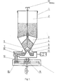
- the container 1 comprises a cylindrical supply chamber 2 terminated at the bottom by a conical chamber 4 for powder flow. These two chambers 2 and 4 are separated from one another by a grid 3 established in the form of ribs arranged radially. At the outlet of the conical flow chamber 4, a conical diaphragm 7 is provided, partially veiling the outlet of the flow chamber.
- valve 5 In the lower part of this flow chamber 4 is arranged, directly above the diaphragm 7 conical, a valve 5 also having a conical shape which is provided for adjusting the width of an annular lumen 6 formed between the valve 5 and the internal surface of the wall of the flow chamber 4, this valve 5 being able to be moved vertically by the operation of a knurled button 13 located outside the container 1 .
- Under container 1 is a second container 8 coupled to a vibrator 11, said container 8 being equipped with an annular furnishing chamber 9 enveloping the conical diaphragm 7.
- This furnishing chamber 9 ends in a track 10 communicating with the inlet of a vertical cylinder 12, the outlet of which is located directly above an annular recess 15 arranged in the rotary hearth 14 mounted on rolling bearing along the axis of the container 1.
- This scraper 1 6 for powder flow has two flow channels, of which l one constitutes a gas inlet channel 17 and the other an ejection channel 18 of the mixture of the powder with the gas. These two channels 17 and 18 communicate with each other by an annular recess segment 15, of which l the gas inlet drives the powder and the outlet of the mixture of powder and gas are directed tangentially to the rotary hearth 14.
Abstract
Description
L'invention a pour objet un doseur de poudres coopérant avec un dispositif technique a flux de gaz ionise par un arc électrique à courant continu destiné à poser un revêtement a composants multiples par voie de projection au pistolet à plasma,ou le débit de poudres à granulation de 5 à 60 /um/micromètres/ implique le besoin du contrôle de l'écoulement.The subject of the invention is a powder metering device cooperating with a technical device with a flow of gas ionized by a direct current electric arc intended to apply a multi-component coating by spraying with a plasma gun, or the flow of powders at granulation from 5 to 60 / µm / micrometers / implies the need for flow control.
Le problème du dosage des poudres de métaux et de leurs composants chimiques,lors du processus de projection au pistolet à plasma,pose de nombreuses difficultés pour maintenir l'écoulement consigné de leurs masses par unité de temps envers le flux de plasma.Cette difficulté est encore accrue du fait que les poudres commerciales sont peu fluantes /poudres non sphériques et poudres très fines/.The problem of metering metal powders and their chemical components during the plasma spraying process poses many difficulties in maintaining the recorded flow of their masses per unit of time towards the plasma flow. further increased by the fact that commercial powders are not very fluid / non-spherical powders and very fine powders /.
On connait déjà un dispositif d'alimentation en poudres du type Twin-10 compact,illustré dans la notice de la société dite Plasma-Technik AG /Suisse/,qui comporte un récipient sous forme d'un cône inversé,à la sortie duquel se trouve un diaphragme tournant conique dont le sommet est dirigé vers le haut,formant à la sortie du récipient une lumière annulaire,réglable par un mouvement axial du diaphragme.Sur la surface conique du diaphragme,en dessous de la lumière annulaire,on a prévu des barres emplacées perpendiculairement envers l'axe longitudinal du diaphragme,destinées à disperser les masses de poudres en chutte.Sous le récipient on a prévu une chambre conique terminée par un entonnoir sous lequel est disposée une sole tournante contre laquelle prend appui d'une manière glissante un plateau fixe dans la partie supérieure,qui présente en dessous un segment annulaire d'évidement ayant à une extrémité un orifice d'admission et a l'autre un orifice d'éjection de la poudre.There is already known a compact Twin-10 type powder supply device, illustrated in the notice of the company known as Plasma-Technik AG / Switzerland /, which comprises a container in the form of an inverted cone, at the outlet of which is finds a conical rotating diaphragm whose apex is directed upwards, forming an annular lumen at the outlet of the container, adjustable by an axial movement of the diaphragm. On the conical surface of the diaphragm, below the annular lumen, bars placed perpendicularly to the longitudinal axis of the diaphragm, intended to disperse the masses of falling powders. A conical chamber provided with a funnel is provided under the container under which is disposed a rotary hearth against which a sliding plate bears against a fixed plate in the upper part, which has below an annular recess segment having at one end an inlet orifice and at the other an orifice powder ejection.
Le fonctionnement de ce dispositif d'alimentation en poudres est le suivant:
- La poudre du récipient s'écoule a travers une lumière annulaire sur la surface conique d'un diaphragme,òu la masse de poudre tombée subit une pulvérisation sur des barres,tombant ensuite dans une chambre conique d'où elle est évacuée à travers un entonnoir par une sole tournante en remplissant un évidement annulaire aménagé dans un plateau fixe.Grâce à la sole tournante,la poudre est entraînée le long de l'évidoment annulaire vers un orifice d'éjection aménagé dans le plateau fixe d'où elle est entraînée par un diffuseur vers le dispositif technique a flux de gaz ionisé par un arc électrique.
- The powder in the container flows through an annular lumen on the conical surface of a diaphragm, where the mass of fallen powder is sprayed on bars, then falls into a conical chamber from which it is discharged through a funnel by a rotating hearth by filling an annular recess arranged in a fixed plate. Thanks to the rotating sole, the powder is entrained along the annular recess towards an ejection orifice arranged in the fixed plateau from where it is entrained by a diffuser towards the technical device with gas flow ionized by an electric arc.
Ce dispositif d'alimentation présente une construction simple,mais il n'est pas apte à assurer un dosage convenable en poudres a petite fluidité,notamment de poudres fines à granulation inférieure a 15µm. Dans la partie inférieure de ce dispositif la poudre est soumise a l'effet de compactags,donc ce fait le dosage de la poudre est irregulier.This feed device has a simple construction, but it is not capable of ensuring a suitable dosage of powders with low fluidity, in particular of fine powders with granulation less than 15 μm. In the lower part of this device the powder is subjected to the effect of compactags, so this fact the dosage of the powder is irregular.
L'invention se propose l'obtention d'un débit régulier en poudres,notamment en poudres fines et a faible fluidité,pour alimenter un dispositif technique à flux de gaz ionisé par un arc électrique appliqué dans le procédé de revêtement au moyen d un flux de plasma.The invention proposes obtaining a regular flow rate of powders, in particular fine powders and of low fluidity, to supply a technical device with a flow of gas ionized by an electric arc applied in the coating process by means of a plasma flow.
De ce fait,on a prévu sous le récipient de poudre un autre récipient mis en mouvement vibratoire,constituant une chambre annulaire d'ameublissement,entourant un diaphragme conique a la sortie,à partir de la chambre de débit du dispositif d'alimentation,cette chambre d'ameublissement étant reliée par une piste grimpante a faible angle d'inclinaison à un cylindre vertical dont la sortie est située directement au-dessus d'un évidement annulaire se trouvant dans la sole tournante située en-dessous du récipient vibrant.A une certaine distance du cylindre,on a prévu un racleur d'écoulement de la poudre,dont la partie inférieure est insérée dans l'évidement annulaire de la sole tournante.Ce racleur d'écoulement de la poudre présente un canal d'entrée de gaz et un canal de sortie du mélange de la poudre avec le gaz,ces canaux étant reliés entre uex par un segment annulaire d'évidoment aménagé sur la sole tournante.Therefore, there is provided under the powder container another container set in vibratory movement, constituting an annular furnishing chamber, surrounding a conical diaphragm at the outlet, from the flow chamber of the supply device, this loosening chamber being connected by a climbing track with a small angle of inclination to a vertical cylinder, the outlet of which is located directly above an annular recess located in the rotating hearth situated below the vibrating container. a certain distance from the cylinder, a powder flow scraper is provided, the lower part of which is inserted into the annular recess of the rotary hearth. This powder flow scraper has a gas inlet channel and an outlet channel for the mixture of the powder with the gas, these channels being connected between uex by an annular segment of evidoment arranged on the rotating hearth.
Le doseur selon l'invention,à part la simplicité de construction,se caractérise par un dosage précis ré- pétable selon le débit consigné en poudres à granulation de 5 a 60 µm, ce débit étant fonction qu'uniquement du nombre de tours de la sole tournante,grâce a quoi il est possible de faire communiquer le doseur à un système automatique de commande du procédé de revêtement à plasma. L'objet de l'invention est illutré par l'exemple de réalisation sur le dessin annexé,où la Fig.1 est uneThe dispenser according to the invention, apart from the simplicity of construction, is characterized by a precise metering repeatable according to the flow rate recorded in powders with granulation from 5 to 60 μm, this flow rate being a function only of the number of revolutions of the rotating floor, whereby it is possible to communicate the metering device to an automatic system for controlling the plasma coating process. The object of the invention is illustrated by the embodiment in the accompanying drawing, where Fig.1 is a
vue d ensemble du doseur dont un fragment en coupe selon le plan A-A est présenté sur la Fig.3; la Fig.2 est une vue du racleur d'écoulement de la poudre en coupe suivant la ligne A-A de la Fig.3,et la Fig.3 est une vue de,la sole tournante en demi-vue d'en haut. Le récipient 1 comporte une chambre cylindrique d'alimentation 2 terminée en bas par une chambre conique 4 de débit en poudres.Ces deux chambres 2 et 4 sont séparées entre elles par une grille 3 établie sous forme de nervures disposées radialement. A la sortie de la chambre conique 4 de débit,on a prévu un diaphragme conique 7 partiellement voilant la sortie de la chambre de débit.4.Dans la partie inférieure de cette chambre de débit 4 est aménagée,directemet au-dessus du diaphragme 7 conique,une soupape 5 présentant aussi une forme conique qui est prévue en vue du réglage de la largeur d'une lumière annulaire 6 formée entre la soupape 5 et la surface interne de la paroi de la chambre de débit 4,cette soupape 5 pouvant être déplacée verticalement par la maneuvre d'un bouton moleté 13 situé hors du récipient 1. Sous le récipient 1 se trouve un second récipient 8 accouplé à un vibrateur 11,ledit récipient 8 étant équipé d'une chambre annulaire d'ameublissement 9 enveloppant la diaphragme conique 7.Cetts chambre d'ameublissement 9 s'achève d'un cote en une piste 10 communiquant avec l'entrée d'un cylindre vertical 12,dont la sortie se trouve directement au-dessus d'un evidement annulaire 15 aménagé dans la sole tournante 14 montée sur palier à roulement selon l'axe du récipient 1. A une certaine distance du cylindre 12 au-dessus de la sole tournante 14,on a prévu un racleur 16 d'écoulement de la poudre,dont la partie inférieure prend appui en glissant contre la paroi annulaire de l'évidement 15 aménagé dans la sole tournante 14.Ce racleur 16 d'écoulement de la poudre présente deux canaux de débit,dont l'un constitue un canal d'admission 17 de gaz et l'autre un canal d'éjection 18 du mélange de la poudre avec le gaz.Ces deux canaux 17 et 18 communiquent entre eux par un segment d'évidement annulaire 15,dont l'entrée du gaz entrains la poudre et dont la sortie du mélange de poudre et de gaz sont dirigées tangentiellement à la sole tournante 14.overview of the dispenser, a fragment of which in section along the plane AA is shown in Fig. 3; Fig.2 is a view of the scraper for the flow of the powder in section along the line AA in Fig.3, and Fig.3 is a view of the rotary hearth in half-view from above. The
Le fonctionnement du doseur suivant l'invention est le suivant:
- La poudre a partir du
récipient 1 est dirigée à travers lagrille 3 vers lachambre 4 conique de débit puis ensuite elle traverse lalumière 6 vers le dia-.phragme conique 7,d'où elle tombe dans la chambre d'ameublissement 9.Sous l'effet des vibrations du récipient 8,la poudre s'ameublie et elle est débitée par lapiste 10 vers lecylindre 12,d'où elle est communiquée a l'évidemont annulaire 15 de la sole tournante 14.Sous l'action du mouvement rotatif de la sole tournante 14,l'évidement annulaire 15 est totalement chargé par une couche uniforme de poudre sur la section entre lecylindre 12 et leracleur 16 d'écoulement.Par leracleur 16 d'écoulement la poudre est entraînée vers le canal d'éjection 18 par le gaz provenant du canal d'admission 17,puis ensuite elle est dirigée vers le pistolet a plasma non montré sur le dessin.
- The powder from the
container 1 is directed through thegrid 3 to theconical flow chamber 4 and then it passes through thelumen 6 towards the dia-.conical phragm 7, from where it falls into thefurnishing chamber 9. Under the effect of the vibrations of the container 8, the powder loosens and it is delivered bytrack 10 to thecylinder 12, from where it is communicated to theannular recess 15 of therotary hearth 1 4. Under the action of the rotary movement of therotary hearth 14, theannular recess 15 is fully loaded by a uniform layer of powder on the section between thecylinder 1 2 and thescraper 16 of flow. By thescraper 16 of flow the powder is entrained towards theejection channel 18 by the gas coming from theintake channel 17, then then it is directed towards the plasma gun not shown on the drawing.
Claims (2)
Applications Claiming Priority (2)
| Application Number | Priority Date | Filing Date | Title |
|---|---|---|---|
| PL25387685A PL144534B1 (en) | 1985-06-07 | 1985-06-07 | Powder dispenser |
| PL253876 | 1985-06-07 |
Publications (2)
| Publication Number | Publication Date |
|---|---|
| EP0208150A2 true EP0208150A2 (en) | 1987-01-14 |
| EP0208150A3 EP0208150A3 (en) | 1987-12-23 |
Family
ID=20027023
Family Applications (1)
| Application Number | Title | Priority Date | Filing Date |
|---|---|---|---|
| EP86107764A Withdrawn EP0208150A3 (en) | 1985-06-07 | 1986-06-06 | Powder dosing apparatus |
Country Status (2)
| Country | Link |
|---|---|
| EP (1) | EP0208150A3 (en) |
| PL (1) | PL144534B1 (en) |
Cited By (3)
| Publication number | Priority date | Publication date | Assignee | Title |
|---|---|---|---|---|
| EP0366798A1 (en) * | 1988-01-19 | 1990-05-09 | Institut Gidrodinamiki Imeni M.A. Lavrentieva Sibirskogo Otdelenia Akademii Nauk Sssr | Device for feeding gun powder to the barrel of a detonation installation |
| RU2463563C1 (en) * | 2011-05-20 | 2012-10-10 | Учреждение Российской академии наук Институт теоретической и прикладной механики им. С.А. Христиановича Сибирского отделения РАН (ИТПМ СО РАН) | Powdered material feeder |
| RU178445U1 (en) * | 2017-11-28 | 2018-04-04 | Федеральное Государственное Унитарное Предприятие "Научно-Производственное Объединение "Техномаш" | Device for dispensing nanosized powder materials |
Families Citing this family (2)
| Publication number | Priority date | Publication date | Assignee | Title |
|---|---|---|---|---|
| RU2445583C1 (en) * | 2010-12-21 | 2012-03-20 | Федеральное Государственное Унитарное Предприятие "Научно-Производственное Объединение "Техномаш" | Dosing unit of powder materials |
| EP2957888A1 (en) | 2014-06-16 | 2015-12-23 | Instytut Technologii Eksploatacji - Panstwowy Instytut Badawczy | Device for dispensing friction material, in particular in an erosion control device |
Citations (4)
| Publication number | Priority date | Publication date | Assignee | Title |
|---|---|---|---|---|
| FR376138A (en) * | 1907-03-26 | 1907-08-01 | Hermann Wolf | Apparatus for the uniform distribution of all substances, from powder to pasty state |
| US3109680A (en) * | 1961-05-24 | 1963-11-05 | Indevco Ltd | Spray coating |
| US3667676A (en) * | 1969-03-26 | 1972-06-06 | Nippon Kogei Kogyo Co | Apparatus for electrostatically coating powders on a workpiece |
| EP0123581A1 (en) * | 1983-03-28 | 1984-10-31 | Societe De Fabrication D'elements Catalytiques S.F.E.C. | Powder delivering apparatus, especially for a heat gun |
Family Cites Families (1)
| Publication number | Priority date | Publication date | Assignee | Title |
|---|---|---|---|---|
| DE2807866C2 (en) * | 1978-02-23 | 1979-09-20 | Plasmainvent Ag, Zug (Schweiz) | Device for the metered supply of powder to a powder processing unit |
-
1985
- 1985-06-07 PL PL25387685A patent/PL144534B1/en unknown
-
1986
- 1986-06-06 EP EP86107764A patent/EP0208150A3/en not_active Withdrawn
Patent Citations (4)
| Publication number | Priority date | Publication date | Assignee | Title |
|---|---|---|---|---|
| FR376138A (en) * | 1907-03-26 | 1907-08-01 | Hermann Wolf | Apparatus for the uniform distribution of all substances, from powder to pasty state |
| US3109680A (en) * | 1961-05-24 | 1963-11-05 | Indevco Ltd | Spray coating |
| US3667676A (en) * | 1969-03-26 | 1972-06-06 | Nippon Kogei Kogyo Co | Apparatus for electrostatically coating powders on a workpiece |
| EP0123581A1 (en) * | 1983-03-28 | 1984-10-31 | Societe De Fabrication D'elements Catalytiques S.F.E.C. | Powder delivering apparatus, especially for a heat gun |
Cited By (4)
| Publication number | Priority date | Publication date | Assignee | Title |
|---|---|---|---|---|
| EP0366798A1 (en) * | 1988-01-19 | 1990-05-09 | Institut Gidrodinamiki Imeni M.A. Lavrentieva Sibirskogo Otdelenia Akademii Nauk Sssr | Device for feeding gun powder to the barrel of a detonation installation |
| EP0366798A4 (en) * | 1988-01-19 | 1990-12-05 | Institut Gidrodinamiki Imeni M.A. Lavrentieva Sibirskogo Otdelenia Akademii Nauk Sssr | Device for feeding gun powder to the barrel of a detonation installation |
| RU2463563C1 (en) * | 2011-05-20 | 2012-10-10 | Учреждение Российской академии наук Институт теоретической и прикладной механики им. С.А. Христиановича Сибирского отделения РАН (ИТПМ СО РАН) | Powdered material feeder |
| RU178445U1 (en) * | 2017-11-28 | 2018-04-04 | Федеральное Государственное Унитарное Предприятие "Научно-Производственное Объединение "Техномаш" | Device for dispensing nanosized powder materials |
Also Published As
| Publication number | Publication date |
|---|---|
| PL253876A1 (en) | 1986-03-11 |
| EP0208150A3 (en) | 1987-12-23 |
| PL144534B1 (en) | 1988-06-30 |
Similar Documents
| Publication | Publication Date | Title |
|---|---|---|
| US4227835A (en) | Apparatus for the metered supply of powder to a powder processing unit | |
| WO2009099197A1 (en) | Spinning air sieving method and device | |
| US3575352A (en) | Carbonated beverage mixing and dispensing nozzle assembly | |
| AU715120B2 (en) | Device and method for metering a particulate substance and apparatus comprising a plurality of such devices | |
| WO1994022587A1 (en) | Aspirating nozzle and accessory systems therefor | |
| RU2441374C2 (en) | Method and device for liquid injection into bulk solids | |
| RU1787263C (en) | Device for batching solid particles in gas flow | |
| US3637135A (en) | Method of and apparatus for spray coating components | |
| JPH05184976A (en) | Spray nozzle device having grooved deflecting face | |
| EP0208150A2 (en) | Powder dosing apparatus | |
| US600547A (en) | Anton mazzanovich | |
| US2496194A (en) | Powder distributor for preventing offset from freshly printed sheets | |
| JP2006528064A (en) | Fluidized bed equipment | |
| EP0030192B1 (en) | Device for introducing a gaseous current into apparatuses for fluidized bed granulation and/or coating | |
| JPS6034916B2 (en) | powder feeding device | |
| JPH01299657A (en) | Apparatus for control discharge of weighed amount of liquid finely distributed in gas | |
| JP2009247999A (en) | Mixer | |
| US3533601A (en) | Methods and apparatus for forming amalgams | |
| US5588787A (en) | Pulse-operated point feeder | |
| US6196263B1 (en) | Methods and apparatus for metering flowable material | |
| JPH0145562B2 (en) | ||
| US5519980A (en) | Filling device for filling into magazine chambers | |
| US421942A (en) | leg-gett | |
| FR2481568A1 (en) | Metering powder or granular material - by rotary cylinder with projections and wiper arranged to give predictable flow of material cleared | |
| RU2263725C1 (en) | Powder feeder |
Legal Events
| Date | Code | Title | Description |
|---|---|---|---|
| PUAI | Public reference made under article 153(3) epc to a published international application that has entered the european phase |
Free format text: ORIGINAL CODE: 0009012 |
|
| 17P | Request for examination filed |
Effective date: 19860724 |
|
| AK | Designated contracting states |
Kind code of ref document: A2 Designated state(s): CH DE FR LI |
|
| PUAL | Search report despatched |
Free format text: ORIGINAL CODE: 0009013 |
|
| AK | Designated contracting states |
Kind code of ref document: A3 Designated state(s): CH DE FR LI |
|
| RIN1 | Information on inventor provided before grant (corrected) |
Inventor name: MIKOS, MICHAL |
|
| 17Q | First examination report despatched |
Effective date: 19880603 |
|
| STAA | Information on the status of an ep patent application or granted ep patent |
Free format text: STATUS: THE APPLICATION IS DEEMED TO BE WITHDRAWN |
|
| 18D | Application deemed to be withdrawn |
Effective date: 19890527 |