EP0207806B1 - Gerät zur Überwachung des systolischen Blutdrucks mit Daten-Aufbereitung - Google Patents
Gerät zur Überwachung des systolischen Blutdrucks mit Daten-Aufbereitung Download PDFInfo
- Publication number
- EP0207806B1 EP0207806B1 EP86305199A EP86305199A EP0207806B1 EP 0207806 B1 EP0207806 B1 EP 0207806B1 EP 86305199 A EP86305199 A EP 86305199A EP 86305199 A EP86305199 A EP 86305199A EP 0207806 B1 EP0207806 B1 EP 0207806B1
- Authority
- EP
- European Patent Office
- Prior art keywords
- pressure
- cuff
- peak
- complex
- stored
- Prior art date
- Legal status (The legal status is an assumption and is not a legal conclusion. Google has not performed a legal analysis and makes no representation as to the accuracy of the status listed.)
- Expired - Lifetime
Links
Images


Classifications
-
- A—HUMAN NECESSITIES
- A61—MEDICAL OR VETERINARY SCIENCE; HYGIENE
- A61B—DIAGNOSIS; SURGERY; IDENTIFICATION
- A61B5/00—Measuring for diagnostic purposes; Identification of persons
- A61B5/02—Detecting, measuring or recording pulse, heart rate, blood pressure or blood flow; Combined pulse/heart-rate/blood pressure determination; Evaluating a cardiovascular condition not otherwise provided for, e.g. using combinations of techniques provided for in this group with electrocardiography or electroauscultation; Heart catheters for measuring blood pressure
- A61B5/021—Measuring pressure in heart or blood vessels
- A61B5/022—Measuring pressure in heart or blood vessels by applying pressure to close blood vessels, e.g. against the skin; Ophthalmodynamometers
-
- A—HUMAN NECESSITIES
- A61—MEDICAL OR VETERINARY SCIENCE; HYGIENE
- A61B—DIAGNOSIS; SURGERY; IDENTIFICATION
- A61B5/00—Measuring for diagnostic purposes; Identification of persons
- A61B5/02—Detecting, measuring or recording pulse, heart rate, blood pressure or blood flow; Combined pulse/heart-rate/blood pressure determination; Evaluating a cardiovascular condition not otherwise provided for, e.g. using combinations of techniques provided for in this group with electrocardiography or electroauscultation; Heart catheters for measuring blood pressure
- A61B5/021—Measuring pressure in heart or blood vessels
- A61B5/02108—Measuring pressure in heart or blood vessels from analysis of pulse wave characteristics
- A61B5/02116—Measuring pressure in heart or blood vessels from analysis of pulse wave characteristics of pulse wave amplitude
-
- A—HUMAN NECESSITIES
- A61—MEDICAL OR VETERINARY SCIENCE; HYGIENE
- A61B—DIAGNOSIS; SURGERY; IDENTIFICATION
- A61B5/00—Measuring for diagnostic purposes; Identification of persons
- A61B5/02—Detecting, measuring or recording pulse, heart rate, blood pressure or blood flow; Combined pulse/heart-rate/blood pressure determination; Evaluating a cardiovascular condition not otherwise provided for, e.g. using combinations of techniques provided for in this group with electrocardiography or electroauscultation; Heart catheters for measuring blood pressure
- A61B5/021—Measuring pressure in heart or blood vessels
- A61B5/022—Measuring pressure in heart or blood vessels by applying pressure to close blood vessels, e.g. against the skin; Ophthalmodynamometers
- A61B5/02225—Measuring pressure in heart or blood vessels by applying pressure to close blood vessels, e.g. against the skin; Ophthalmodynamometers using the oscillometric method
Definitions
- This invention relates to automated blood pressure measuring apparatus and, more particularly to stored program controlled monitors employing the oscillometric method of detection characterised by data purification and enhanced systolic, diastolic and mean blood pressure determination.
- the so-called oscillometric method of measuring blood pressure is one of the most popular methods in commercially available systems. This method relies on measuring changes in arterial counterpressure, such as imposed by an inflatable cuff, which is controllably relaxed or inflated. In some cases the cuff pressure change is continuous, and in others it is incremental. In substantially all, a transducer monitors arterial counterpressure oscillations, and processing apparatus converts select parameters of these oscillations into blood pressure data.
- an inflatable cuff is suitably located on the limb of a patient, and is pumped up to a predetermined pressure. Thereupon, the cuff pressure is reduced in predetermined fixed decrements, at each level of which pressure fluctuations are monitored. These typically consist of a DC voltage with a small superimposed variational component caused by arterial blood pressure pulsations (referred to herein as "oscillatory complexes").
- pulse peak amplitudes above a given threshold are measured and stored. As the decrementing continues, the peak amplitudes will normally increase from a lower amount to a relative maximum, and thereafter will decrease.
- the lowest cuff pressure at which the oscillations have a maximum peak value is representative of mean arterial pressure.
- the cuff pressures obtained when stored oscillation complex pulse peak amplitudes bear predetermined fractional relationships with the largest stored peak correspond to the subject's systolic and diastolic pressures.
- oscillometric blood pressure measurements are effected with non-uniform, cuff pressure-dependent pressure decrements between successive oscillatory complex peak measuring intervals.
- Such a method of effecting oscillometric blood pressure measurements is facilitated by systolic, diastolic and mean blood pressure determining algorithms not heretofore employed.
- GB-A-1589391 describes an apparatus and process for determining systolic pressure in which a blood pressure cuff is used to apply pressure to the arm of a patient. Values of applied pressure are supplied to an interpolation unit, adjacent measurements being interpolated in order to determine the systolic pressure.
- US-A-4461266 discloses a blood pressure monitor which uses incremental steps to obtain blood pressure measurements using the oscillometric method.
- the pulse amplitudes indicate mean arterial pressure when these start to decrease for increasing cuff pressure.
- a large decrease in cuff pressure is made and the incremental step process is restarted until the maximum pulse amplitude is obtained.
- EP-A-0020110 describes a non-invasive vascular waveform transducer and apparatus which can be used to monitor blood flow through the brachial artery when partially occluded by a cuff. Signals which represent the pressure wave proportional to the blood flow and the turbulence created by the blood flow through the partially occluded artery are used to determine heart rate, systolic and diastolic pressures.
- GB-A-2092309 describes a technique wherein blood pressure is measured by using an inflatable cuff to apply external pressure to a patient's body member, and measuring the amplitude of pressure oscillation induced in the cuff by blood flow in the body member as the cuff pressure is decreased in steps from a magnitude above an expected systolic (or diastolic) pressure to a magnitude below the expected systolic (or diastolic) blood pressure.
- the systolic (or diastolic) blood pressure is then determined by making a first linear approximation to a plurality of amplitude measurements occurring below the expected pressure and making a second linear approximation to a plurality of points occurring above the expected pressure, and finding the systolic (or diastolic) pressure by setting the two approximations equal to determine their intercept.
- Both the systolic and the diastolic blood pressure, and also the mean arterial pressure (where the pressure oscillations reach a maximum) may be measured automatically using a microprocessor.
- Yet another object of the present invention is the provision of improved algorithms, methodology and apparatus for determining systolic, diastolic and mean arterial blood pressure.
- a blood pressure cuff is applied about a subject's artery, and inflated above the systolic level, thus fully occluding the artery for a full heart cycle.
- the cuff pressure is thereafter reduced to permit an increasing flow through the progressively less occluded artery, and a measure of the peak amplitudes of the successively encountered oscillatory complexes stored in memory. Also retained is the cuff pressure obtaining for each stored complex peak.
- the stored complex peak-representing data set is corrected for aberrations; and improved data processing operates on the stored (and advantageously corrected) pulse peak data and the corresponding cuff pressure information to determine the subject's systolic, diastolic and mean arterial pressure.
- an automated blood pressure monitor comprising: an inflatable cuff; means for inflating and deflating said cuff, said means being arranged to deflate said cuff in discrete pressure steps of at least 7 Torr (0.933 KPa); pressure transducer means coupled to said cuff for cuff pressure measurement; means responsive to said cuff pressure measurement for generating a signal representing blood pressure pulses; complex peak storing means for storing values characterising the peak amplitudes of said detected pulses at different cuff pressures; cuff pressure storing means for storing the cuff pressures associated with said cuff pressure pulse peak signals; means for locating the maximum complex peak amplitude stored in said complex peak storing means; means for generating a threshold level which is a predetermined fraction of said maximum peak amplitude value; means for selecting peak amplitudes from said complex peak storing means, the selected amplitudes corresponding to a pair of steps which are prior in time to the time at which the maximum peak amplitude occurred
- a method for measuring systolic pressure using an automatic oscillometric blood pressure monitor having a pressurized cuff, means for deflating said cuff, and means for measuring arterial pressure oscillation complexes and the peak of the envelope thereof through measurement of prevailing and time varying cuff pressures, the method comprising the steps of: a) deflating said cuff in discrete pressure steps of at least 7 Torr (0.933 KPa); b) after each said step, detecting oscillation complexes, measuring and storing the peak of the envelope thereof, and storing identification of the associated step; c) finding the amplitude of the largest of said peaks; d) developing a threshold level which is a predetermined fraction of the maximum peak amplitude; e) identifying a pair of steps which are prior in time to the time at which the maximum peak amplitude occurred, and which respectively precede and follow a cuff pressure associated with said threshold level; and f) developing sys
- An artery-occluding cuff is disposed on the subject, e.g., about a subject's upper arm over the brachial artery.
- the cuff is inflated to a pressure which fully occludes the brachial artery, i.e., prevents blood from flowing therethrough at any point in the heart cycle.
- the cuff is then progressively deflated, as in discrete steps.
- a pressure transducer is coupled to the internal cuff pressure and provides an analog signal characterising the blood pressure oscillatory complexes when they begin to occur (i.e., when the maximum heart pressure corresponding to contraction of the heart's left ventricle exceeds the instantaneously obtaining artery-occluding cuff pressure).
- the peak values of the complex signals are determined in hardware or software.
- the oscillometric blood pressure measurements as typified by the disclosed principles are effected under stored program control, as via a microprocessor operative in conjunction with a program containing read only memory (ROM or PROM), and a variable content random access memory (RAM) which stores the cuff pressures, oscillatory complex peak amplitudes, and other processing operand variables.
- the microprocessor receives the cuff pressure readings generated by the pressure transducer, for example as processed by a peak detector, amplifier and analog-to-digital convertor, and supplies all output control signals required, e.g., to open and close one or more cuff deflating valves.
- the cuff may be inflated directly by an air pump; and deflated in fixed, discrete steps under microprocessor control.
- the cuff may be principally or entirely inflated by the pressurised contents of an air reservoir; and/or deflation may proceed in variable, cuff pressure-dependent steps via selected one or ones of plural deflating valves.
- a second form of spurious data occurs when the pattern of stored pulse peak values departs from the physiologically mandated sequence of values which progressively increase to a peak and then progressively decrease.
- CP(I) The cuff pressure, measured by the transducer pneumatically coupled to the artery occluding cuff, obtaining during the i-th deflation step.
- CP(I) is an indexed array, i.e., there exists a plurality of values for CP(I) characterizing each of the i deflation steps.
- ⁇ A(I) The peak amplitude of the oscillometric oscillation (i.e., the complex peak amplitude) occurring at the i-th step. Where multiple complexes are measured during each prevailing deflation pressure, ⁇ A(I) is the average of two (or more) peak amplitudes during the i-th step.
- ⁇ A(I) is an indexed array.
- ⁇ A(MAX) The peak value of the array of averaged oscillatory blood pressure complex amplitudes. MAX The time interval when the peak complex ⁇ A(MAX) occurred.
- Variable Functional Quantity Represented LVL An intermediate processing variable representing a predetermined fraction of ⁇ A(MAX). SYS The subject's measured systolic pressure.
- DIAU DIAL Intermediate processing variables representing upper and lower interpolated diastolic pressure computational variables.
- DIA The subject's measured diastolic pressure.
- Variable Functional Quantity Represented AMP The complex pulse peak for the deflation interval following that for which the pressure oscillation amplitude was the maximum.
- MAPL An intermediate processing variable employed in the final mean arterial pressure computation.
- MAP The subject's mean arterial blood pressure.
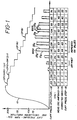
- Fig. 1 there is depicted wave forms with associated data characterizing the generation of data for an oscillatory blood pressure measurement - and purging (overcoming) bad data constituents.
- the cuff artery occluding pressure for a measurement cycle is characterized by a wave form 10.
- the cuff pressure rapidly increases to a maximum above the subject's systolic pressure, and is then deflated in a sequence of steps to a point below the diastolic pressure.
- the sequence of cuff deflation steps is indicated by the time interval signalling digits 1,2, ... , (lowest row 18 in the data table portion of Fig. 1).
- the internal pressure characterizing the cuff pressure at each step i is given by the data array CP(1),CP(2), ... (upper data table row 12).
- Each step (time interval) is made sufficiently long to include at least two heart beats. Accordingly, at least two cuff pressure complex pulses 21 i and 221 are measured during each interval after such pulses begin.
- two oscillometric complex pulses 21 and 22 are generated and measured, the two pulses having an average peak amplitude 23 (the processor variable array value initially stored in ⁇ A(I)).
- the measured oscillation amplitude array ( ⁇ A(I)) is shown in the third row 14 of the Fig. 1 data table for each time interval.
- the oscillation pressure amplitude ⁇ A(I) data row would not contain any +1 values which signify an impeded measurement.
- the data pattern in the third row of the data table for the oscillation amplitudes would exhibit a pattern of successively increasing numbers to a peak value, followed by progressively decreasing values - all without adjacent equal ⁇ A(I) values.
- the data processing in accordance with the instant invention functions to compute appropriate corrected ⁇ A(I) values (the third data table row 15 in Fig. 1) for the oscillation amplitude entries requiring correction.
- ⁇ A(I) ( ⁇ A(I-1) + ⁇ A(I+1))/2.
- the first of the contiguous equal pair is replaced by the average of the amplitudes of the complex peaks measured at the next lower and next higher occluding cuff pressures. See, for example, Eq. 1 and, more particularly, the comparable relationship in functional block 30 of Fig, 2.
- Fig. 2 operates on the measured average oscillation amplitudes (the second data table row 14 in Fig. 1) and generates the corrected ⁇ A(I) values shown in the third row 15 of Fig. 1.
- step 15 reads the next value ⁇ A(I) (proceeding toward the right along the Fig. 1 data table row 14) and test 18 determines whether the value stored in ⁇ A(I) equals the error-signalling value +1. If as is the usual case it does not (indicating that the value measured was presumptively free of artifacts and the like), control passes to equality test 27.
- functional block 23 implements Eq. 1, i.e., replaces the +1 former contents of memory cell ⁇ A(I) corresponding to cuff pressure CP(I) with the average value of the oscillation amplitude measured at the next lower ( ⁇ A(I-1)) and next higher non-plus one ( ⁇ A(I+1)) deflation steps.
- the processing steps 18 and 23 thus purge the measured pressure peak amplitude storage contents (the second row of the Fig. 1 data table) of all +1 values, replacing these by the average value of the measurements made during immediately adjacent deflation steps (corrected ⁇ A(I) contents being illustrated in row 15).
- Test 27 next examines the current operand ⁇ A(I) for the proscribed equality with the previous value ⁇ A(I-1). If, as is normally the case, the contents of ⁇ A(I) and ⁇ A(I-1) differ ("NO" branch from test 27), processing flows to test 32 to determine whether each of the N elements of ⁇ A(I) have been processed. If they have not, control returns to block 15 to read in and process the next ⁇ A(I) element of the array in the third row 15 of the Fig. 1 data table. When all elements have been processed, control exits from the Fig. 2 data purification routine to data processing point 33 to proceed with the next (unrelated) task for the microprocessor.
- control passes to step 30 which replaces the assumed erroneous element ⁇ A(I-1) - (the value which should differ from ⁇ A(I) but did not) with the average of the two immediately contiguous elements, as by ⁇ A(I-1) ( ⁇ A(I)+ ⁇ A(I-2))/2.
- the corrected set of ⁇ A(I) is shown in the third row 15 of the Fig. 1 data table.
- the oscillation amplitude value during the cuff pressure step (time interval) "4" is corrected from the error-signalling +1 value to a peak amplitude 14, representing the average of measurements 4 and 25 at cuff pressures 25 kPa (187 Torr) and 20.4 kPa (153 Torr) during the immediately contiguous time intervals 3 and 5.
- the first (pressure step 6) of two equal measured oscillation amplitude pulses of value 63 during periods 6 and 7, corresponding to occluding cuff pressures of 18.7 kPa (140 Torr) and 17.1 kPa (128 Torr), is corrected to a value of 44 representing the average of the contiguous measured amplitudes of 63 and 25 units.
- the corrected array ⁇ A(I) as represented by the fourth row 15 in Fig. 1 thus comprises value from which each of the systolic, diastolic and mean arterial blood pressures may be determined either in accordance with the improved algorithms below discussed or employing the algorithms of the above referenced patents and parent applications.
- the data purification above discussed provides more accurate measurements than was heretofore the case; and also permits blood pressures to be determined more quickly, obviating the need for repeated deflation steps when unacceptable artifact or noise corrupted data is sensed.
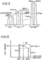
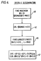
- Pulse complex wave form processing typifying systolic blood pressure determination is illustrated in Fig. 3, and a flow chart for the underlying data processing is set forth in Fig. 4.
- systolic pressure is determined by:
- Equations 4 and 5 make an initial assumption that the peak value occurred during the first interval and load a provisional peak value storing variable ⁇ AMAX with the value ⁇ A(1).
- the loop between Equations 6 and 10 sequentially examines every element of the ⁇ A(I) array from 2 to N, updating ⁇ AMAX only when the value ⁇ A(K) - (K being the loop index) exceeds the previously assumed ⁇ AMAX value.
- the variable MAX contains the value of I such that ⁇ A(MAX) is the largest value in the array.
- the value LVL is shown by the dashed line 50 in Fig. 3.
- the next following operation 45 finds the first time interval (L) preceding MAX for which the oscillation amplitude peak is less than LVL, i.e., less than one-half of the peak value ⁇ A(MAX), thereby finding the two contiguous values (L, L+1) having peak amplitudes which bound the value in LVL.
- the appropriate interval identification (MAX-J) is stored in the variable location L.
- the value of the systolic pressure is estimated by assuming a linear variation in cuff pressure between the values CP(L) and CP(L+1), and a linear variation between the corresponding oscillation amplitude ⁇ A(L) and ⁇ A(L+1).
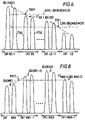
- Fig. 6 Pulse complex wave form processing characterizing diastolic blood pressure determination is illustrated in Fig. 6; and a flow chart for the underlying diastolic data processing algorithm is depicted in Fig. 7.
- diastolic pressure is determined by:
- the above-described procedure is illustrated in the blood pressure complex depiction of Fig. 6 and the Fig. 7 flow chart.
- the peak ⁇ A(MAX) is first located as by the processing of Equations 4-10.
- the upper and lower peak amplitude fractions DIAU and DIAL are next determined (steps 64 and 65 of Fig. 7 corresponding to the labeled horizontal dash lines in Fig. 6).
- Step 69 finds the first time inerval (UD) following MAX at which the peak amplitude ⁇ A(UD) is lower than the value stored in DIAU (as by processing analogous to that of Equations 12 through 15 replacing "MAX-J" with "MAX+J").
- step 72 performs the trapezoidal interpolation analogous to that of Fig.
- the functional steps 73 and 74 of Fig. 7 perform in a manner directly analogous to operations 69 and 72, locating the cuff pressure DIAL by interpolation for the intervals when the peak complex amplitudes bound the LDLVL value equal ⁇ A(MAX) times 0.55. This latter search is conducted from ⁇ A(i) at the lowest cuff pressure, then working toward higher cuff pressures. Finally, the subject's diastolic pressure (DIA) is computed as the average of the contents stored in DIAU and DIAL (step 82). To illustrate with a numerical example, again employing the data portion of Fig. 1, Eq. 22.
- mean arterial pressure is determined by:
- the denominator (2.9 in Eq. 26) may be somewhat lower for operation in a "stat" mode, e.g., 2.85.
- Step 101 finds the peak interval MAX (for example, by execution comparable to Equations 4-10).
- a processing variable AMP is set equal to the peak value ⁇ A(MAX+1) of the complex following the interval MAX (step 105) and the interval MN1 is next determined (step 106) as the first occurring complex less than the value AMP (i.e., ⁇ A(MAX+1)) to the left of time MAX in Fig. 8 (e.g., by processing comparable to Equations 12-15).
- An interpolation is then conducted to find the point MAPL (Fig. 8; step 111 in Fig. 9) and the final processing operation 113 finds the subject's mean arterial pressure by implementing Equation 26.
- measured data may be enhanced by replacing data lost through measurement artifacts or the like or deviations from a proper data pattern by approximated values.
- Specific data processing algorithms were presented and discussed for the computation of a subject's measured systolic, diastolic and mean arterial blood pressures.
- the pressure measurement mode is described above as stepped deflation from an initial inflation above the subject's systolic pressure.
- the measurement of the instant invention can alternatively be performed by stepped inflation from an initial sub-diastolic cuff pressure.
Claims (14)
- Automatisches Blutdrucküberwachungsgerät mit:
einer aufpumpbaren Manschette ;
Mittel zum Aufpumpen und zur Druckminderung für die Manschette, wobei mit diesen Mitteln der Manschettendruck in diskreten Druckstufen von zumindest 7 Torr (0,933 KPa) absenkbar ist;
einem mit der Manschette verbundenen Druckwandler zum Messen des Manschettendrucks (CP(I));
auf den gemessenen Manschettendruck (CP(I)) ansprechende Mittel zur Erzeugung eines die Blutdruckpulsationen darstellenden Signals;
eine Speichereinrichtung für die Peakbereiche zur Speicherung von Werten (φA(I)), die die Spitzenwerte der ermittelten Pulsationen bei verschiedenen Manschettendruckwerten (CP(I)) darstellen;
eine weitere Speichereinrichtung zur Speicherung der Manschettendruckwerte (CP(I)) in Zusammenhang mit den Spitzensignalen (φA(I)) der Manschettendruckpulsationen;
Mittel zur Bestimmung des größten Spitzenwertes (φA(MAX)) der Peakbereiche, der in der Speichereinrichtung für die Peakbereiche gespeichert ist;
Mittel zur Erzeugung eines Schwellenwertes (LVL), der ein vorgegebener Bruchteil des größten Spitzenwertes (φA(MAX)) ist;
Mittel zur Auswahl von Spitzenwerten (φA(I)) aus der Speichereinrichtung für die Peakbereiche, wobei die ausgewählten Werte einem Stufenpaar (L,L+1) entsprechen, welches dem größten Spitzenwert (φA(MAX)) zeitlich vorangeht, und welches einem dem genannten Schwellenwert zugeordneten Manschettendruck vorangeht bzw. folgt, und wobei die ausgewählten Spitzenwerte benachbart sind zum Schwellenwert (LVL) und bei höheren Manschettendruckwerten erzeugt worden sind als derjenige, der dem maximalen Signal der Pulsationspeake zugeordnet ist; und
Mittel zur Bestimmung des systolischen Blutdrucks (SYS) mittels Interpolation aus den ausgewählten Spitzenwerten (φA(I)) benachbart zum Schwellenwert (LVL) und aus den entsprechenden Manschettendruckwerten (CP(I)) die in dem Speicher für die Manschettendruckwerte abgespeichert sind, wobei eine vorbestimmte funktionale Zunahme zwischen den ausgewählten Spitzenwerten benachbart zum Schwellenwert (LVL) vorausgesetzt ist. - Überwachungsgerät nach Anspruch 1, dadurch gekennzeichnet, daß die Mittel zum Aufpumpen der Manschette diese bis zu einem vorgegebenen Druck oberhalb des systolischen Blutdrucks (SYS) aufpumpen; wobei außerdem eine Kontrolleinrichtung vorgesehen ist, die auf die Mittel zur Manschettendruckminderung einwirkt, um zumindest während des Hauptteils des systolischen Meßzyklus den Druck schrittweise zu vermindern.
- Überwachungsgerät nach Anspruch 1 oder 2, dadurch gekennzeichnet, daß das Überwachungsgerät von einem digitalen Prozessor gesteuert ist und mittels eines gespeicherten Programms arbeitet, und daß die Mittel zur Erzeugung eines Schwellenwertes (LVL) einen Rechner darstellen.
- Überwachungsgerät nach einem der Ansprüche 1 bis 3, dadurch gekennzeichnet, daß die Mittel zur Interpolation Mittel zur Berechnung eines Druckwertes aufweisen, der zwischen den Druckwerten liegt, die aus der Speichereinrichtung für die Manschettendruckwerte stammen.
- Überwachungsgerät nach einem der Ansprüche 1 bis 4, dadurch gekennzeichnet, daß eine Datenkorrektureinrichtung vorgesehen ist, welche anhand der die Spitzenwerte in einem Manschettendruckbereich beschreibenden Werte (φA(I)) arbeitet, die in der Speichereinrichtung für die Peakbereiche abgelegt sind, um Datenungenauigkeiten zu korrigieren.
- Überwachungsgerät nach Anspruch 5, dadurch gekennzeichnet, daß ein vorbestimmtes Zeichen in der Speichereinrichtung für die Peakbereiche gespeichert ist, um eine verfehlte Messung eines Oszillationspeaks des Manschettendrucks anzuzeigen, und daß die Datenkorrektureinrichtung Mittel aufweist, die auf das Auftreten dieses vorgewählten Zeichens ansprechen, um die Inhalte der Speichereinrichtung für die Peakbereiche zu überprüfen, und um das genannte Zeichen durch eine Reihe von gespeicherten Meßwerten aus einem Peakbereich des Manschettendrucks zu ersetzen, wobei zumindest einer dieser Meßwerte bei einem höheren Manschettendruck als der dem vorgewählten Zeichen zugeordnete Druck gewonnen wurde, und zumindest ein anderer Meßwert bei einem tieferen Druck.
- Überwachungsgerät nach Anspruch 6, dadurch gekennzeichnet, daß die Mittel zur Datenüberprüfung und zum Datenaustausch ihrerseits Mittel zum Ersetzen des vorgewählten Zeichens durch einen Durchschnittswert der Spitzenwerte aus einem Manschettendruckwertebereich, die in der betreffenden Speichereinrichtung gespeichert sind, aufweisen, wobei zumindest einer dieser Spitzenwerte bei einem höheren Manschettendruck als der dem vorgewählten Zeichen zugeordneten Druck erhalten wurde, und zumindest ein anderer dieser Werte einem Manschettendruck zugeordnet war, der niedriger als der für das vorgewählte Zeichen ist.
- Überwachungsgerät nach einem der Ansprüche 5 bis 7, dadurch gekennzeichnet, daß die Datenkorrektureinrichtung Mittel aufweist, um die Speichereinrichtung für den Manschettendruckbereich nach dem Auftreten zweier gleich großer Spitzenwerte zu durchsuchen, die bei aufeinanderfolgenden abnehmenden Manschettendruckwerten auftreten, und weiterhin eine auf die genannten Mittel ansprechende Einrichtung, um eine der beiden gespeicherten, gleich großen Werte durch den Mittelwert des nächsthöheren und nächstniedrigeren Wertes zu ersetzen, die in der betreffenden Speichereinrichtung gespeichert sind.
- Überwachungsgerät nach Anspruch 8, dadurch gekennzeichnet, daß der Ersatzwert das arithmetische Mittel der genannten zwei Werte darstellt.
- Überwachungsgerät nach Anspruch 9, dadurch gekennzeichnet, daß der Ersatzwert der Durchschnittswert des zeitlich vorangehend und des zeitlich nachfolgend gemessenen Wertes der gespeicherten Spitzenwerte im Peakbereich darstellt.
- Überwachungsgerät nach einem der Ansprüche 5 bis 10, dadurch gekennzeichnet, daß die Datenkorrektureinrichtung vor den Mitteln zur Bestimmung der des größten Spitzenwertes im Peakbereich (φA(MAX)) wirksam ist.
- Verfahren zur Messung des systolischen Blutdrucks (SYS) unter Verwendung eines automatischen oszillatorischen Blutdruckmeßgeräts mit einer druckbeaufschlagten Manschette, Mittel zur Manschettendruckminderung und einer Einrichtung zur Messung des arteriellen Blutdruckes in Oszillationsbereichen sowie des Maximalwertes seiner Einhüllenden mittels Messung der vorherrschenden und sich zeitlich ändernden Manschettendruckwerte, gekennzeichnet durch folgende Verfahrensschritte:a) der Manschettendruck wird in diskreten Schritten von zumindest 7 Torr (0,933 KPa) abgesenkt;b) nach jedem dieser Schritte werden die Oszillationsbereiche ermittelt und der jeweilige Spitzenwert (φA(I)) ihrer Einhüllenden wird gemessen und gespeichert, wobei eine Kennung des zugehörigen Schrittes mitabgespeichert wird;c) die Größe (φA(MAX)) des höchsten dieser Spitzenwerte wird ermittelt;d) ein Schwellenwert (LVL), der ein vorgegebener Bruchteil dieses größten Spitzenwertes (φA(MAX)) ist, wird festgelegt;e) ein Stufenpaar (L, L+1), welches zeitlich dem größten Spitzenwert (φA(MAX)) vorausgeht, und welches dem dem genannten Schwellenwert (LVL) zugeordneten Manschettendruck vorausgeht bzw. folgt, wird bestimmt; und schließlichf) werden Größen für den systolischen Blutdruck (CP(L), CP(L+1)) berechnet, wobei eine vorgegebene funktionale Zunahme zwischen den Werten (φA(L)) und (φA(L+1)) bei diesem Stufenpaar (L, L+1) vorausgesetzt wird.
- Verfahren nach Anspruch 12, dadurch gekennzeichnet, daß zwischen den Verfahrensschritten (b) und (c) ein weiterer Verfahrenschritt eingefügt wird, bei dem die Folge der genannten Spitzenwerte in bezug zu einer vorherbestimmten Gesamtsequenz untersucht wird und bestimmte Werte durch geeignete Werte ersetzt werden, wenn erstere in vorherbestimmter Weise von denen der genannten Folge abweichen.
- Verfahren nach Anspruch 12 oder 13, dadurch gekennzeichnet, daß die vorherbestimmte funktionale Zunahme eine lineare Funktion der Zeit ist.
Applications Claiming Priority (2)
| Application Number | Priority Date | Filing Date | Title |
|---|---|---|---|
| US75182785A | 1985-07-05 | 1985-07-05 | |
| US751827 | 1985-07-05 |
Publications (3)
| Publication Number | Publication Date |
|---|---|
| EP0207806A2 EP0207806A2 (de) | 1987-01-07 |
| EP0207806A3 EP0207806A3 (en) | 1988-06-08 |
| EP0207806B1 true EP0207806B1 (de) | 1996-06-19 |
Family
ID=25023659
Family Applications (1)
| Application Number | Title | Priority Date | Filing Date |
|---|---|---|---|
| EP86305199A Expired - Lifetime EP0207806B1 (de) | 1985-07-05 | 1986-07-04 | Gerät zur Überwachung des systolischen Blutdrucks mit Daten-Aufbereitung |
Country Status (10)
| Country | Link |
|---|---|
| EP (1) | EP0207806B1 (de) |
| AT (1) | ATE139430T1 (de) |
| BR (1) | BR8603143A (de) |
| CA (1) | CA1270565A (de) |
| DE (1) | DE3650531T2 (de) |
| DK (1) | DK321686A (de) |
| FI (1) | FI862853A (de) |
| MX (1) | MX171712B (de) |
| NO (1) | NO862720L (de) |
| ZA (1) | ZA865004B (de) |
Families Citing this family (1)
| Publication number | Priority date | Publication date | Assignee | Title |
|---|---|---|---|---|
| US4627440A (en) | 1985-07-05 | 1986-12-09 | Critikon, Inc. | Sphygmomanometric cuff pressurizing system |
Citations (1)
| Publication number | Priority date | Publication date | Assignee | Title |
|---|---|---|---|---|
| GB2092309A (en) * | 1981-01-29 | 1982-08-11 | Bard Inc C R | Blood Pressure Measurement |
Family Cites Families (3)
| Publication number | Priority date | Publication date | Assignee | Title |
|---|---|---|---|---|
| GB1589391A (en) * | 1976-09-07 | 1981-05-13 | American Optical Corp | Apparatus and process for determining systolic pressure |
| US4295471A (en) * | 1979-05-25 | 1981-10-20 | Kaspari William J | Non-invasive vascular waveform transducer and apparatus |
| US4461266A (en) * | 1982-04-29 | 1984-07-24 | Critikon, Inc. | Adaptive incremental blood pressure monitor |
-
1986
- 1986-07-03 CA CA000512998A patent/CA1270565A/en not_active Expired - Lifetime
- 1986-07-04 BR BR8603143A patent/BR8603143A/pt not_active IP Right Cessation
- 1986-07-04 NO NO862720A patent/NO862720L/no unknown
- 1986-07-04 FI FI862853A patent/FI862853A/fi not_active IP Right Cessation
- 1986-07-04 DE DE3650531T patent/DE3650531T2/de not_active Expired - Lifetime
- 1986-07-04 EP EP86305199A patent/EP0207806B1/de not_active Expired - Lifetime
- 1986-07-04 DK DK321686A patent/DK321686A/da not_active Application Discontinuation
- 1986-07-04 ZA ZA865004A patent/ZA865004B/xx unknown
- 1986-07-04 MX MX003021A patent/MX171712B/es unknown
- 1986-07-04 AT AT86305199T patent/ATE139430T1/de not_active IP Right Cessation
Patent Citations (1)
| Publication number | Priority date | Publication date | Assignee | Title |
|---|---|---|---|---|
| GB2092309A (en) * | 1981-01-29 | 1982-08-11 | Bard Inc C R | Blood Pressure Measurement |
Also Published As
| Publication number | Publication date |
|---|---|
| ZA865004B (en) | 1988-02-24 |
| ATE139430T1 (de) | 1996-07-15 |
| DE3650531D1 (de) | 1996-07-25 |
| CA1270565A (en) | 1990-06-19 |
| DK321686D0 (da) | 1986-07-04 |
| EP0207806A3 (en) | 1988-06-08 |
| BR8603143A (pt) | 1987-03-17 |
| FI862853A0 (fi) | 1986-07-04 |
| DE3650531T2 (de) | 1996-11-21 |
| EP0207806A2 (de) | 1987-01-07 |
| NO862720L (no) | 1987-01-06 |
| DK321686A (da) | 1987-01-06 |
| NO862720D0 (no) | 1986-07-04 |
| MX171712B (es) | 1993-11-11 |
| FI862853A (fi) | 1987-01-06 |
Similar Documents
| Publication | Publication Date | Title |
|---|---|---|
| EP0207807B1 (de) | Gerät zur Überwachung des diastolischen Blutdruckes mit Daten-Aufbereitung | |
| US4754761A (en) | Automated mean arterial blood pressure monitor with data enhancement | |
| US5170795A (en) | Oscillometric blood pressure monitor and method employing non-uniform pressure decrementing steps | |
| EP0409210B1 (de) | Verfahren und Vorrichtung zum Unterscheiden zwischen genauer und ungenauer Blutdruckmessungen in Gegenwart eines Störsignales | |
| US4408614A (en) | Blood pressure measurement with Korotkov sound artifact information detection and rejection | |
| US4926873A (en) | Method for measuring blood pressure and apparatus for automated blood pressure measuring | |
| US5253648A (en) | Method and apparatus for excluding artifacts from automatic blood pressure measurements | |
| US4543962A (en) | Method of automated blood pressure detection | |
| US4669485A (en) | Apparatus and method for continuous non-invasive cardiovascular monitoring | |
| US7074192B2 (en) | Method and apparatus for measuring blood pressure using relaxed matching criteria | |
| US7465273B2 (en) | Method for monitoring pre-eclamptic patients | |
| US20060184055A1 (en) | Method and system for determination of pulse rate | |
| US20120157791A1 (en) | Adaptive time domain filtering for improved blood pressure estimation | |
| US4774960A (en) | Method and apparatus for measuring blood pressure | |
| US6517495B1 (en) | Automatic indirect non-invasive apparatus and method for determining diastolic blood pressure by calibrating an oscillation waveform | |
| US5653241A (en) | Blood-pressure monitor apparatus | |
| US5868679A (en) | Blood-pressure monitor apparatus | |
| EP0208521B1 (de) | Automatisches Mittel zur arteriellen Blutdrucküberwachung mit verbesserten Daten | |
| EP0207806B1 (de) | Gerät zur Überwachung des systolischen Blutdrucks mit Daten-Aufbereitung | |
| AU623116B2 (en) | Oscillometric blood pressure monitor employing non-uniform pressure decrementing steps | |
| EP0150176B1 (de) | Blutdruckmessung mit nachweis und unterdrückung von störgeräuschen im korotkoff-signal | |
| JPS6148339A (ja) | 電子血圧計 |
Legal Events
| Date | Code | Title | Description |
|---|---|---|---|
| PUAI | Public reference made under article 153(3) epc to a published international application that has entered the european phase |
Free format text: ORIGINAL CODE: 0009012 |
|
| AK | Designated contracting states |
Kind code of ref document: A2 Designated state(s): AT BE CH DE FR GB IT LI LU NL SE |
|
| PUAL | Search report despatched |
Free format text: ORIGINAL CODE: 0009013 |
|
| AK | Designated contracting states |
Kind code of ref document: A3 Designated state(s): AT BE CH DE FR GB IT LI LU NL SE |
|
| 17P | Request for examination filed |
Effective date: 19881112 |
|
| RAP1 | Party data changed (applicant data changed or rights of an application transferred) |
Owner name: CRITIKON, INC. (A FLORIDA CORPORATION) |
|
| RAP3 | Party data changed (applicant data changed or rights of an application transferred) |
Owner name: CRITIKON, INC. |
|
| 17Q | First examination report despatched |
Effective date: 19910328 |
|
| GRAH | Despatch of communication of intention to grant a patent |
Free format text: ORIGINAL CODE: EPIDOS IGRA |
|
| GRAA | (expected) grant |
Free format text: ORIGINAL CODE: 0009210 |
|
| AK | Designated contracting states |
Kind code of ref document: B1 Designated state(s): AT BE CH DE FR GB IT LI LU NL SE |
|
| REF | Corresponds to: |
Ref document number: 139430 Country of ref document: AT Date of ref document: 19960715 Kind code of ref document: T |
|
| REG | Reference to a national code |
Ref country code: CH Ref legal event code: NV Representative=s name: E. BLUM & CO. PATENTANWAELTE |
|
| REF | Corresponds to: |
Ref document number: 3650531 Country of ref document: DE Date of ref document: 19960725 |
|
| GRAH | Despatch of communication of intention to grant a patent |
Free format text: ORIGINAL CODE: EPIDOS IGRA |
|
| ITF | It: translation for a ep patent filed |
Owner name: SOCIETA' ITALIANA BREVETTI S.P.A. |
|
| ET | Fr: translation filed | ||
| PLBE | No opposition filed within time limit |
Free format text: ORIGINAL CODE: 0009261 |
|
| STAA | Information on the status of an ep patent application or granted ep patent |
Free format text: STATUS: NO OPPOSITION FILED WITHIN TIME LIMIT |
|
| 26N | No opposition filed | ||
| PGFP | Annual fee paid to national office [announced via postgrant information from national office to epo] |
Ref country code: SE Payment date: 19980707 Year of fee payment: 13 |
|
| PGFP | Annual fee paid to national office [announced via postgrant information from national office to epo] |
Ref country code: AT Payment date: 19980713 Year of fee payment: 13 |
|
| PGFP | Annual fee paid to national office [announced via postgrant information from national office to epo] |
Ref country code: LU Payment date: 19980720 Year of fee payment: 13 |
|
| PGFP | Annual fee paid to national office [announced via postgrant information from national office to epo] |
Ref country code: CH Payment date: 19980722 Year of fee payment: 13 |
|
| PGFP | Annual fee paid to national office [announced via postgrant information from national office to epo] |
Ref country code: NL Payment date: 19980728 Year of fee payment: 13 |
|
| PGFP | Annual fee paid to national office [announced via postgrant information from national office to epo] |
Ref country code: BE Payment date: 19980914 Year of fee payment: 13 |
|
| PG25 | Lapsed in a contracting state [announced via postgrant information from national office to epo] |
Ref country code: LU Free format text: LAPSE BECAUSE OF NON-PAYMENT OF DUE FEES Effective date: 19990704 Ref country code: AT Free format text: LAPSE BECAUSE OF NON-PAYMENT OF DUE FEES Effective date: 19990704 |
|
| PG25 | Lapsed in a contracting state [announced via postgrant information from national office to epo] |
Ref country code: SE Free format text: THE PATENT HAS BEEN ANNULLED BY A DECISION OF A NATIONAL AUTHORITY Effective date: 19990730 |
|
| PG25 | Lapsed in a contracting state [announced via postgrant information from national office to epo] |
Ref country code: LI Free format text: LAPSE BECAUSE OF NON-PAYMENT OF DUE FEES Effective date: 19990731 Ref country code: CH Free format text: LAPSE BECAUSE OF NON-PAYMENT OF DUE FEES Effective date: 19990731 Ref country code: BE Free format text: LAPSE BECAUSE OF NON-PAYMENT OF DUE FEES Effective date: 19990731 |
|
| BERE | Be: lapsed |
Owner name: CRITIKON INC. Effective date: 19990731 |
|
| PG25 | Lapsed in a contracting state [announced via postgrant information from national office to epo] |
Ref country code: NL Free format text: LAPSE BECAUSE OF NON-PAYMENT OF DUE FEES Effective date: 20000201 |
|
| REG | Reference to a national code |
Ref country code: CH Ref legal event code: PL |
|
| EUG | Se: european patent has lapsed |
Ref document number: 86305199.1 |
|
| NLV4 | Nl: lapsed or anulled due to non-payment of the annual fee |
Effective date: 20000201 |
|
| REG | Reference to a national code |
Ref country code: GB Ref legal event code: IF02 |
|
| PGFP | Annual fee paid to national office [announced via postgrant information from national office to epo] |
Ref country code: GB Payment date: 20050629 Year of fee payment: 20 |
|
| PG25 | Lapsed in a contracting state [announced via postgrant information from national office to epo] |
Ref country code: IT Free format text: LAPSE BECAUSE OF NON-PAYMENT OF DUE FEES;WARNING: LAPSES OF ITALIAN PATENTS WITH EFFECTIVE DATE BEFORE 2007 MAY HAVE OCCURRED AT ANY TIME BEFORE 2007. THE CORRECT EFFECTIVE DATE MAY BE DIFFERENT FROM THE ONE RECORDED. Effective date: 20050704 |
|
| PGFP | Annual fee paid to national office [announced via postgrant information from national office to epo] |
Ref country code: FR Payment date: 20050718 Year of fee payment: 20 |
|
| PGFP | Annual fee paid to national office [announced via postgrant information from national office to epo] |
Ref country code: DE Payment date: 20050831 Year of fee payment: 20 |
|
| PG25 | Lapsed in a contracting state [announced via postgrant information from national office to epo] |
Ref country code: GB Free format text: LAPSE BECAUSE OF EXPIRATION OF PROTECTION Effective date: 20060703 |
|
| REG | Reference to a national code |
Ref country code: GB Ref legal event code: PE20 |