EP0207409A2 - Valve system for an adjustable hydraulic damper - Google Patents
Valve system for an adjustable hydraulic damper Download PDFInfo
- Publication number
- EP0207409A2 EP0207409A2 EP86108485A EP86108485A EP0207409A2 EP 0207409 A2 EP0207409 A2 EP 0207409A2 EP 86108485 A EP86108485 A EP 86108485A EP 86108485 A EP86108485 A EP 86108485A EP 0207409 A2 EP0207409 A2 EP 0207409A2
- Authority
- EP
- European Patent Office
- Prior art keywords
- valve
- valve system
- bypass channel
- flow
- channel
- Prior art date
- Legal status (The legal status is an assumption and is not a legal conclusion. Google has not performed a legal analysis and makes no representation as to the accuracy of the status listed.)
- Granted
Links
- 239000012530 fluid Substances 0.000 claims abstract description 30
- 238000013016 damping Methods 0.000 claims description 63
- 239000006096 absorbing agent Substances 0.000 claims description 29
- 230000035939 shock Effects 0.000 claims description 29
- 230000006835 compression Effects 0.000 claims description 27
- 238000007906 compression Methods 0.000 claims description 27
- 239000007788 liquid Substances 0.000 claims description 9
- 238000010276 construction Methods 0.000 description 3
- 238000007789 sealing Methods 0.000 description 3
- 238000010586 diagram Methods 0.000 description 2
- 230000000694 effects Effects 0.000 description 2
- 230000006872 improvement Effects 0.000 description 2
- 230000004044 response Effects 0.000 description 2
- 230000009471 action Effects 0.000 description 1
- 230000006978 adaptation Effects 0.000 description 1
- 230000000712 assembly Effects 0.000 description 1
- 238000000429 assembly Methods 0.000 description 1
- 230000008901 benefit Effects 0.000 description 1
- 238000011156 evaluation Methods 0.000 description 1
- 238000007654 immersion Methods 0.000 description 1
- 238000005192 partition Methods 0.000 description 1
- 238000005293 physical law Methods 0.000 description 1
- 230000009467 reduction Effects 0.000 description 1
- 238000010992 reflux Methods 0.000 description 1
- 238000005096 rolling process Methods 0.000 description 1
- 238000000926 separation method Methods 0.000 description 1
- 239000000725 suspension Substances 0.000 description 1
Images


Classifications
-
- F—MECHANICAL ENGINEERING; LIGHTING; HEATING; WEAPONS; BLASTING
- F16—ENGINEERING ELEMENTS AND UNITS; GENERAL MEASURES FOR PRODUCING AND MAINTAINING EFFECTIVE FUNCTIONING OF MACHINES OR INSTALLATIONS; THERMAL INSULATION IN GENERAL
- F16F—SPRINGS; SHOCK-ABSORBERS; MEANS FOR DAMPING VIBRATION
- F16F9/00—Springs, vibration-dampers, shock-absorbers, or similarly-constructed movement-dampers using a fluid or the equivalent as damping medium
- F16F9/32—Details
- F16F9/44—Means on or in the damper for manual or non-automatic adjustment; such means combined with temperature correction
- F16F9/46—Means on or in the damper for manual or non-automatic adjustment; such means combined with temperature correction allowing control from a distance, i.e. location of means for control input being remote from site of valves, e.g. on damper external wall
- F16F9/466—Throttling control, i.e. regulation of flow passage geometry
- F16F9/467—Throttling control, i.e. regulation of flow passage geometry using rotary valves
- F16F9/468—Throttling control, i.e. regulation of flow passage geometry using rotary valves controlling at least one bypass to main flow path
Definitions
- the invention relates to a valve system for controllable, hydraulic vibration dampers, in particular for telescopic shock absorbers according to the preamble of the main claim.
- Such a valve system in a shock absorber is shown in DE-AS 1 580 775.
- the open flow channel runs through an intermediate damping wall and meets the centrally clamped disc spring of a seat valve.
- the bypass channel runs partially in a control valve housing and opens into the flow channel with its last section provided in the intermediate partition wall.
- the bypass channel can be closed by a control slide.
- the shock absorber has a softer or harder damping behavior.
- the range of variation is essentially determined by the flow cross-sections of the channels.
- the previously known shock absorber cannot be used for certain applications since the damping behavior can only be varied sufficiently in the lower piston speed range.
- the damping force characteristics remain largely unaffected. An effective improvement in comfort can only be achieved if the characteristic curves can also be varied in this speed range.
- Adjustable shock absorbers are also known, in which a second spring-loaded valve can optionally be connected in parallel to a permanently active seat valve.
- the disadvantage of this version is that it takes up almost twice as much space compared to the damper pistons used today.
- valve system There is only very limited space in a shock absorber.
- the valve system must therefore be compact. This is especially true when the valve system is to be provided in the damper piston.
- the object of the invention is to develop a generic valve system so that it allows a relatively large constructive freedom for the design of the damping behavior with a compact design.
- bypass channel is guided over its entire length separately from the flow channel in the valve system.
- the separate routing of the two channels opens up the possibility of choosing the point of contact of the bypass channel with the seat valve independently of that of the flow channel in order to achieve different damper effects.
- the outlet cross section of the respective channel in the area of the seat valve can be designed differently. These options give the designer greater scope for designing the response and damping behavior of the vibration damper.
- the valve systems of the vibration dampers especially when they are used as shock absorbers for motor vehicles, generally have a so-called constant flow.
- This constant flow shows how already derived from the name, a constant flow cross-section and enables an exchange of the damping fluid between the working chambers past the poppet valve.
- the constant flow is provided in the area of the seat valve.
- the valve seat is designed so that the valve is not able to close completely.
- such a constant flow can now be assigned to the flow channel and the bypass channel. This creates further scope for the design or adaptation to the respective application.
- the seat valve on the damper piston of a shock absorber consists of a spring washer package clamped in the center.
- the flow channel and the bypass channel meet the spring assembly at different radial distances from the clamping point. Due to the lever ratios achieved in this way, the damping fluid in the outer channel, with the same flow cross section, causes the spring assembly to lift off the valve seat even at a lower pressure. In this case, it is advisable to let the flow channel near the clamping point and the bypass channel meet the spring assembly on the edge of the disc. If the slide valve closes the bypass channel, you get the hard setting of the shock absorber. When the slide valve is open, the bypass channel causes the seat valve to open when, as already explained, the damping fluid pressure is lower, ie, however, again at lower piston speeds. This gives the shock absorber a soft damping characteristic.
- the variation of the radial distances can still be combined with a different number of channels of the same type within the system.
- different flow cross sections of the individual channels can be realized.
- the construction receives a different gradation of the hard and soft adjustment of the shock absorber.
- An embodiment in which the bypass channel widens into a large outlet opening in the mouth region has proven particularly advantageous. Due to the physical laws of pressure, force and area, within the scope of the variation of the different flow cross-sections there is the further possibility of realizing a large pressure cross-section with an essentially very narrow channel cross-section at the outlet point.
- valve system allows the damping behavior to be set in a simple manner both in the compression stage and in the rebound stage.
- two check valves are provided for this purpose within the damper piston, each of which blocks the corresponding flow direction.
- the closure member is opened in an expedient embodiment divides into two cup-shaped components and each of these components is assigned a channel, flow channel or bypass channel.
- a compression spring acts on the two components. However, it is more advantageous to assign a separate compression spring to each component. In this way you get the possibility to combine different spring rates with each other and thus to achieve different settings of the damping behavior.
- these compression springs can be connected in series or in parallel if the closure member is designed accordingly.
- the valve system has been assumed to have two settings, hard and soft.
- the invention also allows a valve system with several stages.
- the bypass channel separates into two separate channels, which can be closed individually by the slide valve. This gives a first, hard setting of the vibration damper when both channels of the bypass channel are closed. With a second, middle setting, the control slide opens one of the two bypass channels. And finally, with the third, soft setting, both bypass channels are open.
- the invention also allows a compact design, for example in the case of a damper piston equipped with the valve system.
- the entire valve system is arranged within the damper piston in this case.
- the invention also allows a different damping behavior in the rebound and compression stages.
- a secondary arm of the bypass channel is closed in one of the stages, usually in the rebound stage, by a check valve. This non-return valve then opens in the pressure stage and allows the damping fluid to flow back into the second working chamber bypassing the seat valve through the secondary arm of the bypass channel.
- Fig. 2 shows a controllable, hydraulic vibration damper, as is usually used in wheel suspensions of motor vehicles.
- the shock absorber has an outer jacket tube 1 and an inner jacket tube 2 arranged concentrically therein.
- the two casing tubes 1 and 2 are connected to one another by a base part 3 and a closure piece 4.
- the jacket tube 2 receives a hollow piston rod 5 which, at its immersed end, carries a damper piston 7 via a sleeve-shaped intermediate piece 6 attached to it.
- the damper piston 7 separates the interior of the casing tube 2 into a first working chamber 8 and a second working chamber 9.
- a compensation chamber 10 is formed between the outer casing tube 1 and the inner casing tube 2.
- the components have corresponding transverse bores 12 on their walls, which allow the flow of damping fluid from the working chamber 8 via the damper piston 7 to the working chamber 9.
- By turning the control sleeve 11 closes these cross-flow bores 12. This is done via a servomotor 13 which is also arranged in the piston rod and which acts on the control sleeve 11 via a reduction gear 14.
- the damper piston 7 is fastened to a lower, stepped and tubular section.
- a passage opening 15 in the wall of the intermediate piece 6 leads to a channel 16 which runs obliquely downwards and outwards within the damper piston 7. It opens onto a spring-loaded seat valve 17, which consists of a disc spring assembly clamped in the middle.
- a further flow channel 18 passes through the damper piston 7. This flow channel 18 opens in the direction of the working chamber 8 and, like the channel 16, strikes the spring assembly of the seat valve 17, albeit at a smaller radial distance from the clamping point.
- the transverse bores 12 and the passage opening 15 and the path between them in the intermediate piece 6 and the channel 16 form the bypass channel, while the channel 18 is to be regarded as the open flow channel.
- the valve system described in this way works, as explained in more detail, in the rebound stage, that is to say when the piston rod 5 is pulled upwards.
- a similar valve system is provided in the bottom part 3 for the pressure stage.
- a corresponding control needle 11 ' can be seen again, which can be rotated axially via a motor 13' and gear 14 '.
- cross bores 12 'in the sleeve 6' open the way to a seat valve 17 '.
- a comparable flow channel 18 ' also acts on this seat valve 17'.
- An evaluation electronics controls the servomotor 13, through which the control sleeve 11 either releases the cross bores 12 or closes them.
- the shock absorber has its hard setting. If the piston rod 5 is pulled out in this case, damping fluid flows from the working chamber 8 into the working chamber 9 via the open flow channel 18. In order to open the seat valve 17, a certain pressure of the damping fluid is required, which in turn depends on the speed at which the damping piston 17 is pulled upwards.
- damping liquid also flows through the bypass channel and also meets the seat spring 17 at the end of the channel section 16, but at a greater radial distance from the clamping point. Due to the resulting larger lever arm, the damping fluid in the bypass channel is able to lift the spring assembly even at a lower pressure. In addition, there is a larger opening gap, so that more damping fluid can escape overall. The shock absorber is softer in this state, so it can react even at lower fluid pressures.
- the shock absorber In the rebound stage, the shock absorber also sucks damping fluid from the compensating chamber 10 through the bottom valve into this working chamber 9 due to the resulting increase in volume of the working chamber.
- the damping fluid flows through a channel 19, which also leads to a centrally clamped disc spring assembly 20. This flow rate, as shown in FIG. 2, cannot be changed in its volume flow. It is a conventional reflux valve.
- the valve system controls the shock absorber in the bottom part, ie depending on whether the control needle 11 'opens or closes the flow openings 12', the shock absorber assumes a harder or softer characteristic.
- the valve system operates in accordance with that in the damper piston 7.
- the valve system according to FIG. 2 also has a constant flow, at least in the area of the seat valve 17 or 17 ', but this is described in more detail in connection with FIG. 5.
- the damper piston 7 of a monotube telescopic shock absorber is shown on an enlarged scale compared to FIG. 2.
- a control pin 23 is rotatably held, which has a concentric, downwardly open blind bore 24.
- transverse bores 12 which are aligned with corresponding transverse bores in the intermediate piece 22.
- a further flow bore 25 and a corresponding passage opening in the intermediate piece 22 lead to a longitudinal channel 26, which is formed by an inner wall of the damper piston 7 and an outer wall of the intermediate piece 22.
- the longitudinal channel 26 leads to annular channels 27, 28 which run concentrically around the intermediate piece 22 and which produce the connection to a plurality of pocket-shaped recesses 29, 30 formed on the underside and top of the annular piston 7.
- pocket-shaped recesses are covered by the spring assemblies of seat valves 31 and 32.
- the blind bore 24 widens in its central section in the area of the through bore 25 and receives two valve bodies 33, 34 designed as conical tips. These valve bodies 33, 34 close the blind hole 24 symmetrically to the flow opening 25 upwards and downwards. They are pressed onto their valve seats by a compression spring 35.
- the damper piston also has two types of oblique flow channels, one designated 36 and the other 37.
- the flow channels 36 have constant flows 38 and the pocket-shaped recesses 29 constant flows 39.
- the function of the constant flows is explained with reference to FIG. 5.
- the valve system according to FIGS. 3 and 4 enables control of the damping characteristics in the rebound and compression stages.
- the damping fluid In the rebound stage, the damping fluid only flows through the flow channels 36 to the seat valve 31 when the transverse bores 12 are closed.
- damping fluid also flows through the cross bores 12, blind hole 24, flow bore 25, longitudinal channel 26 and annular channel 27 into the recesses 31 the valve body 34 into the open position while the valve body 33 is pressed onto its valve seat.
- the pocket-shaped recesses result in large pressure areas on the disc spring assembly of the seat valve 31, which in turn has the consequence that this seat valve opens even at low pressures.
- the damping liquid flows in the opposite direction through the flow channel 37 and also enters the open end of the blind hole 24, provided that the control pin 23 has switched the cross holes 12 to pass.
- the damping liquid lifts the valve body 13 from its seat and presses the valve body 34 into the closed position.
- the damping fluid flows through the flow bore 25, the longitudinal channel 26 and the ring channel 28 into the pocket-shaped recesses 30. Otherwise the valve system acts in a comparable manner in the rebound and compression stages.
- the seat valve 40 consists of an eccentrically arranged valve plate 41 which presses a compression spring 42 against its seat on the underside of the valve body 7.
- the eccentric arrangement in turn results in a comparatively small, radial distance between the flow channel 18, which is arranged vertically here, and the line of action of the compression spring 42.
- the channel 16, which runs obliquely downwards, as part of the bypass channel, opens into a larger, radial distance on the valve plate 41.
- This arrangement again gives a hard setting when the control sleeve 11, which is connected here to a shaft, blocks the bypass and a soft setting when it releases it.
- a non-closable constant flow opening 43 is provided between the outlet opening of the flow channel 18 and the upper side of the valve plate 41.
- a similar flow opening 44 is formed between the channel 16 and the valve plate 41.
- the slide valve which closes the bypass channel
- the closure member of the seat valve is separated in two versions into two pot-shaped components arranged one inside the other, which are telescopically displaceable.
- the inner component 47 of the left-hand embodiment overlaps the outer component 48 in the radial direction with a flange serving as a valve plate.
- this flange section has a passage opening 49 aimed at a collar of the outer component 48.
- the outer component 52 is pressed against the underside of the damping piston 7 by a compression spring 53.
- the inner component 54 is supported on the outer component 52 via a compression spring 55.
- this component 54 closes a channel section 56 of the bypass channel to be shown in more detail.
- the bypass channel in the sense of the invention is in turn formed by transverse bores 12 in the wall of a hollow piston rod 57 and by corresponding openings in the rotary valve 45 or a channel section 58 formed from transverse and axial bores in the axial slide 46.
- An end piece 59 the is screwed into the piston rod 57, forms a further section of the bypass channel with a central through bore 60.
- cross channels 61 which in the left embodiment open into the passage opening 49 and in the right embodiment into the channel section 56.
- a spring-loaded check valve 62 closes the through hole, which in this section functions as a secondary arm of the bypass channel represents.
- a flow channel 18 passes through the damper piston 7 in the vertical direction and widens at the top to a larger receiving opening.
- the flow channel 18 is only visible in the left version; but it is correspondingly also provided in the right version.
- the lower end of the flow channel 18 closes the inner component 47 with its radial flange on the left, the outer one on the right (and not recognizable) Component 52.
- an oblique return line 63 can also be seen on the left, which in turn is provided in the same way on the right.
- the return line 63 opens downwards and is closed at its upper end by a conventional spring-loaded plate valve.
- the damping liquid presses on the outer component 52 via the (not visible here) channel 18.
- the damping liquid also presses on the inner component 54 via the bypass channel, which in turn presses on the compression spring 55 Passes force to the outer component 52.
- the two compression springs 55 and 53 there is a series connection of the two compression springs 55 and 53.
- the two exemplary embodiments according to FIG. 6 also allow control in the pressure stage. If the rotary slide valve 45 or axial slide valve 46 closes the bypass channel, the liquid is exchanged in this stage via the channel 63. When the bypass channel is open, however, additional damping liquid flows through the through-bore 60 via the check valve 62 of the end piece 59 into the upper working chamber. In this case, the shock absorber gets a softer identifier.
- FIG. 7 shows an axial slide 64, which is designed as a stepped piston and is guided with an annular collar 65 in a hollow piston rod 66 of a shock absorber 67.
- a damping piston 7 is pushed over the lower end of the piston rod 66 and fastened there.
- the damping piston 7 has only one return flow channel 68, otherwise the entire valve system is arranged within the piston rod 66. This results in a compact structure.
- a middle piece 72 provided with flow channels 69, 70, 71 is fastened below the axial slide 64.
- a helical spring 73 presses a hat-shaped closing body 74 against the underside of this center piece 72, which thereby closes the flow channel 69.
- a sealing plug 75 is arranged axially displaceably, which is pressed against the underside of the center piece 72 by a compression spring 76 which is supported on the bottom of the hat-shaped closing body 74 and essentially closes the flow channels 70 and 71.
- the axial slide 64 has at its lower end a spike-shaped extension 77 which is able to dip into the flow channel 71 and to close it.
- a shoulder 78 above the extension 77 enables the axial slide 64 to close the flow channels 70 with a sufficient immersion depth.
- the shock absorber 67 in the rebound 3 allows different hardness settings.
- the axial slide 64 is fully retracted. It thus closes the flow channel 71, the flow channels 70 and, with its ring collar 65, the transverse bores 12 in the wall of the piston rod 66.
- the damping fluid can only flow through the channels 69 while overcoming the spring force 73 into the other working chamber.
- the axial slide 64 has moved upward and thus also clears the flow channel 71.
- the damping fluid flowing through thus obtains a larger effective pressure area on the sealing plug 75 compared to the second setting, and is thereby able to move it even at low pressures.
- the piston speed is plotted on the abscissa 83 and the damping force on the ordinate 84.
- the curve d shows the conditions if, for example in FIG. 5, the bypass channel was closed and the constant flow 43 were not present, so that damping fluid (without leakage losses) can only flow through the flow channel 18. It can be seen that the damping force must rise to a certain value, here designated 79, before the seat valve 40 opens. A movement of the damping piston is not possible below this value due to the incompressibility of the damping fluid. This means that small forces that act on the vibration damper are not reduced. This leads to a loss of comfort.
- Curve b shows the conditions when the control sleeve 11 according to FIG. 5 releases the bypass channel.
- the response level is much lower here and is labeled 80.
- Curve c shows the situation when, for example, the embodiment according to FIG. 5 is provided with constant flow 43.
- damping fluid can pulsate between the individual working chambers in the respective stage, compression or rebound, right from the start.
- the damping piston moves even at low forces acting on it, which, for. B. derive from the rolling movements of the vehicle body. In this way, an improvement in comfort in the area below the line d or b is achieved.
- the flow resistance of the damping fluid increases exponentially due to this constant flow 43. From point 81, the seat valve 40 then opens and the course is essentially determined by curve d.
Landscapes
- Engineering & Computer Science (AREA)
- General Engineering & Computer Science (AREA)
- Mechanical Engineering (AREA)
- Fluid-Damping Devices (AREA)
Abstract
Description
Die Erfindung bezieht sich auf ein Ventilsystem für steuerbare, hydraulische Schwingungsdämpfer, insbesondere für Teleskopstoßdämpfer nach dem Oberbegriff des Hauptanspruchs.The invention relates to a valve system for controllable, hydraulic vibration dampers, in particular for telescopic shock absorbers according to the preamble of the main claim.
Ein derartiges Ventilsystem in einem Stoßdämpfer zeigt die DE-AS 1 580 775. Der offene Durchflußkanal durchzieht eine Dämfpungszwischenwand und trifft auf die mittig eingespannte Scheibenfeder eines Sitzventils. Der Bypass-Kanal verläuft teilweise in einem Steuerschiebergehäuse und mündet mit seinem letzten, in der Dämfpungszwischenwand vorgesehenen Abschnitt in den Durchflußkanal. Über einen Steuerschieber läßt sich der Bypass-Kanal verschließen.Such a valve system in a shock absorber is shown in DE-AS 1 580 775. The open flow channel runs through an intermediate damping wall and meets the centrally clamped disc spring of a seat valve. The bypass channel runs partially in a control valve housing and opens into the flow channel with its last section provided in the intermediate partition wall. The bypass channel can be closed by a control slide.
Je nachdem, ob der Steuerschieber den Bypass-Kanal freigibt oder verschließt, weist der Stoßdämpfer ein weicheres oder härteres Dämpfungsverhalten auf. Dabei bestimmt sich die Variationsbreite im wesentlichen nach den Durchlfußquerschnitten der Kanäle. Der vorbekannte Stoßdämpfer ist für bestimmte Anwendungsfälle nicht brauchbar, da bei ihm das Dämpfungsverhalten nur im unteren Kolbengeschwindigkeitsbereich ausreichend variiert werden kann. Bei hohen Kolbengeschwindigkeiten (Bereich der Rad-Eigenfrequenz), bei denen die Dämpfkräfte im wesentlichen durch das federbelastete Sitzventil bestimmt werden, bleiben die Dämpfkraft-Kennlinien weitgehend unbeeinflußt. Eine wirksame Komfortverbesserung kann nur erreicht werden, wenn die Kennlinien auch in diesem Geschwindigkeitsbereich variiert werden können.Depending on whether the spool releases or closes the bypass channel, the shock absorber has a softer or harder damping behavior. The range of variation is essentially determined by the flow cross-sections of the channels. The previously known shock absorber cannot be used for certain applications since the damping behavior can only be varied sufficiently in the lower piston speed range. At high piston speeds (range of the natural wheel frequency), at which the damping forces are essentially determined by the spring-loaded seat valve, the damping force characteristics remain largely unaffected. An effective improvement in comfort can only be achieved if the characteristic curves can also be varied in this speed range.
Bekannt sind auch verstellbare Stoßdämpfer, bei denen zu einem ständig wirksamen Sitzventil wahlweise ein zweites federbelastetes Ventil parallel geschaltet werden kann. Der Nachteil dieser Ausführung ist der nahezu doppelt so große Platzbedarf im Vergleich zu den heute verwendeten Dämpferkolben.Adjustable shock absorbers are also known, in which a second spring-loaded valve can optionally be connected in parallel to a permanently active seat valve. The disadvantage of this version is that it takes up almost twice as much space compared to the damper pistons used today.
In einem Stoßdämpfer sind nur sehr beengte Platzverhältnisse gegeben. Das Ventilsystem muß demnach kompakt aufgebaut sein. Das gilt vor allem dann, wenn das Ventilsystem im Dämpferkolben vorgesehen sein soll.There is only very limited space in a shock absorber. The valve system must therefore be compact. This is especially true when the valve system is to be provided in the damper piston.
Aufgabe der Erfindung ist es, ein gattungsgemäßes Ventilsystem so weiterzubilden, daß es bei kompakter Bauweise eine verhältnismäßig große konstruktive Freiheit für die Auslegung des Dämpfungsverhaltens erlaubt.The object of the invention is to develop a generic valve system so that it allows a relatively large constructive freedom for the design of the damping behavior with a compact design.
Die Aufgabe wird erfindungsgemäß dadurch gelöst, daß im Ventilsystem der Bypass-Kanal auf seiner ganzen Länge getrennt vom Durchflußkanal geführt ist.The object is achieved in that the bypass channel is guided over its entire length separately from the flow channel in the valve system.
Die getrennte Führung der beiden Kanäle eröffnet die Möglichkeit, die Auftreffstelle des Bypass-Kanals auf das Sitzventil unabhängig von der des Durchflußkanales zu wählen, um unterschiedliche Dämpferwirkungen zu erzielen. Außerdem kann der Austrittsquerschnitt des jeweiligen Kanals im Bereich des Sitzventils unterschiedlich ausgelegt sein. Durch diese Wahlmöglichkeiten ergibt sich für den Konstrukteur ein größerer Spielraum für die Auslegung des Ansprech- und Dämpfungsverhalten des Schwingungsdämpfers.The separate routing of the two channels opens up the possibility of choosing the point of contact of the bypass channel with the seat valve independently of that of the flow channel in order to achieve different damper effects. In addition, the outlet cross section of the respective channel in the area of the seat valve can be designed differently. These options give the designer greater scope for designing the response and damping behavior of the vibration damper.
Dazu kommt ein weiterer Vorteil. Die Ventilsysteme der Schwingungsdämpfer weisen, insbesondere wenn sie als Stoßdämpfer für Kraftfahrzeuge verwendet werden, in der Regel einen sogenannten Konstantdurchfluß auf. Dieser Konstantdurchfluß weist, wie sich aus dem Namen schon ergibt, einen konstanten Durchflußquerschnitt auf und ermöglicht einen Austausch der Dämpfungsflüssigkeit zwischen den Arbeitskammern am Sitzventil vorbei. Bei gebräuchlichen Stoßdämpferausführungen ist der Konstantdurchfluß im Bereich des Sitzventils vorgesehen. Dabei ist der Ventilsitz so ausgearbeitet, daß das Ventil nicht in der Lage ist vollständig zu schließen. Bei der erfindungsgemäßen Ausführung kann nun dem Durchflußkanal und dem Bypass-Kanal ein solcher Konstantdurchfluß zugeordnet werden. Dadurch ergibt sich ein weiterer Spielraum für die konstruktive Auslegung bzw. Anpassung an den jeweiligen Anwendungsfall.There is another advantage. The valve systems of the vibration dampers, especially when they are used as shock absorbers for motor vehicles, generally have a so-called constant flow. This constant flow shows how already derived from the name, a constant flow cross-section and enables an exchange of the damping fluid between the working chambers past the poppet valve. With conventional shock absorber designs, the constant flow is provided in the area of the seat valve. The valve seat is designed so that the valve is not able to close completely. In the embodiment according to the invention, such a constant flow can now be assigned to the flow channel and the bypass channel. This creates further scope for the design or adaptation to the respective application.
Soweit im Rahmen dieser Anmeldung von einem Durchflußkanal und einem Bypass-Kanal gesprochen wird, schließt das nicht aus, daß in einem Ventilsystem mehrere Kanäle der gleichen Art vorgesehen sind.Insofar as there is talk of a flow channel and a bypass channel in the context of this application, this does not exclude that several channels of the same type are provided in a valve system.
In einer zweckmäßigen Ausführung besteht das Sitzventil am Dämpferkolben eines Stoßdämpfers aus einem mittig eingespannten Federscheibenpaket. Der Durchflußkanal und der Bypass-Kanal treffen in unterschiedlich radialen Abständen von der Einspannstelle auf das Federpaket. Aufgrund der dadurch erzielten Hebelverhältnisse bewirkt die Dämpfungsflüssigkeit im äußeren Kanal bei gleichem Durchflußquerschnitt schon bei einem geringeren Druck das Abheben des Federpakets vom Ventilsitz. Es ist in diesem Fall angebracht, den Durchflußkanal in der Nähe der Einspannstelle und den Bypass-Kanal am Scheibenrand auf das Federpaket treffen zu lassen. Verschließt das Schieberventil den Bypass-Kanal, so erhält man die harte Einstellung des Stoßdämpfers. Bei geöffnetem Schieberventil bewirkt der Bypass-Kanal das Öffnen des Sitzventils bei, wie bereits dargelegt, geringerem Druck der Dämpfungsflüssigkeit, d. h. wiederum aber auch, bei geringeren Kolbengeschwindigkeiten. Der Stoßdämpfer erhält dadurch eine weiche Dämpfungscharakteristik.In an expedient embodiment, the seat valve on the damper piston of a shock absorber consists of a spring washer package clamped in the center. The flow channel and the bypass channel meet the spring assembly at different radial distances from the clamping point. Due to the lever ratios achieved in this way, the damping fluid in the outer channel, with the same flow cross section, causes the spring assembly to lift off the valve seat even at a lower pressure. In this case, it is advisable to let the flow channel near the clamping point and the bypass channel meet the spring assembly on the edge of the disc. If the slide valve closes the bypass channel, you get the hard setting of the shock absorber. When the slide valve is open, the bypass channel causes the seat valve to open when, as already explained, the damping fluid pressure is lower, ie, however, again at lower piston speeds. This gives the shock absorber a soft damping characteristic.
Die Variation der radialen Abstände kann noch mit einer unterschiedlichen Anzahl von Kanälen der gleichen Art innerhalb des Systems kombiniert werden. Darüber hinaus lassen sich unterschiedliche Durchflußquerschnitte der einzelnen Kanäle verwirklichen. Mit jeder Kombination erhält die Konstruktion eine andere Abstufung der harten und weichen Einstellung des Stoßdämpfers. Besonders vorteilhaft hat sich eine Ausführung gezeigt, bei der im Mündungsbereich der Bypass-Kanal sich zu einer großen Austrittsöffnung erweitert. Durch die physikalischen Gesetzmäßigkeiten von Druck, Kraft und Fläche ergibt sich im Rahmen der Variation der unterschiedlichen Durchflußquerschnitte die weitere Möglichkeit, bei einem im wesentlichen sehr engen Kanalquerschnitt an der Austrittsstelle einen großen Druckquerschnitt zu verwirklichen.The variation of the radial distances can still be combined with a different number of channels of the same type within the system. In addition, different flow cross sections of the individual channels can be realized. With each combination, the construction receives a different gradation of the hard and soft adjustment of the shock absorber. An embodiment in which the bypass channel widens into a large outlet opening in the mouth region has proven particularly advantageous. Due to the physical laws of pressure, force and area, within the scope of the variation of the different flow cross-sections there is the further possibility of realizing a large pressure cross-section with an essentially very narrow channel cross-section at the outlet point.
Es versteht sich von selbst, daß diese Variationsmöglichkeiten nicht nur bei solchen Schwingungsdämpfern mit mittig eingespannten Federpaket ausgebildet werden können, sondern überall dort, wo das Sitzventil sich als federbelastetes Plattenventil darstellt. Auch kann in einem solchen Fall das Plattenventil außermittig angeordnet sein, so daß die beschriebenen Hebelwirkungen auch bei solchen Ventilsystemen sich einstellt, bei denen die Durchflußkanäle rotationssymmetrisch im Dämpferkolben angeordnet sind.It goes without saying that these possible variations can be formed not only in the case of such vibration dampers with a spring assembly clamped in the center, but wherever the seat valve is a spring-loaded plate valve. In such a case, the plate valve can also be arranged off-center, so that the described lever effects also occur in those valve systems in which the flow channels are arranged rotationally symmetrically in the damper piston.
Schließlich sind nach diesem Prinzip auch mer als zwei Dämpfkraftstufen realisierbar.Finally, more than two damping force levels can also be realized according to this principle.
Das erfindungsgemäße Ventilsystem erlaubt in einfacher Weise die Einstellung des Dämpfungsverhaltens sowohl in der Druck- als auch in der Zugstufe. In einer vorteilhaften Ausführung sind hierzu innerhalb des Dämpferkolbens zwei Rückschlagventile vorgesehen, die jeweils die entsprechende Durchflußrichtung sperren.The valve system according to the invention allows the damping behavior to be set in a simple manner both in the compression stage and in the rebound stage. In an advantageous embodiment, two check valves are provided for this purpose within the damper piston, each of which blocks the corresponding flow direction.
Die Trennung der beiden Kanäle auf ihrer gesamten Stecke erlaubt darüber hinaus weitere konstruktive Gestaltungsmöglichkeiten. So ist in einer zweckmäßigen Ausführung das Verschlußorgan aufge teilt in zwei topfförmige Bauteile und jedem dieser Bauteile ist ein Kanal, Durchfluß- oder Bypass-Kanal zugeordnet. Die beiden Bauteile werden von einer Druckfeder beaufschlagt. Vorteilhafter jedoch ist es, jedem Bauteil eine getrennte Druckfeder zuzuordnen. Auf diese Weise erhält man die Möglichkeit, unterschiedliche Federraten miteinander kombinieren zu können und damit unterschiedliche Einstellungen des Dämpfungsverhaltens zu erreichen. Darüber hinaus können diese Druckfedern bei entsprechender Ausgestaltung des Verschlußorgans in Serie oder parallel geschaltet sein.The separation of the two channels along their entire path also allows further design options. So the closure member is opened in an expedient embodiment divides into two cup-shaped components and each of these components is assigned a channel, flow channel or bypass channel. A compression spring acts on the two components. However, it is more advantageous to assign a separate compression spring to each component. In this way you get the possibility to combine different spring rates with each other and thus to achieve different settings of the damping behavior. In addition, these compression springs can be connected in series or in parallel if the closure member is designed accordingly.
Bisher wurde von einer zweifachen Einstellungsmöglichkeit, hart und weich, des Ventilsystems ausgegangen. Die Erfindung erlaubt aber auch ein Ventilsystem mit mehreren Stufen. Zu diesem Zweck trennt sich der Bypass-Kanal in zwei getrennte Kanäle auf, die einzeln von dem Schieberventil veschlossen werden können. Dadurch erhält man eine erste, harte Einstellung des Schwingungsdämpfers, wenn beide Kanäle des Bypass-Kanals geschlossen sind. Bei einer zweiten, mittleren Einstellung öffnet der Steuerschieber einen der beiden Bypass-Kanäle. Und schließlich sind bei der dritten, weichen Einstellung beide Bypass-Kanäle geöffnet.So far, the valve system has been assumed to have two settings, hard and soft. The invention also allows a valve system with several stages. For this purpose, the bypass channel separates into two separate channels, which can be closed individually by the slide valve. This gives a first, hard setting of the vibration damper when both channels of the bypass channel are closed. With a second, middle setting, the control slide opens one of the two bypass channels. And finally, with the third, soft setting, both bypass channels are open.
Neben all diesen konstruktiven Möglichkeiten erlaubt die Erfindung auch eine kompakte Bauweise, beispielsweise bei einem mit dem Ventilsystem ausgerüsteten Dämpferkolben. In einer vorteilhaften Ausführung ist in diesem Fall das gesamte Ventilsystem innerhalb des Dämpferkolbens angeordnet.In addition to all of these design options, the invention also allows a compact design, for example in the case of a damper piston equipped with the valve system. In an advantageous embodiment, the entire valve system is arranged within the damper piston in this case.
Schließlich erlaubt die Erfindung neben der Einstellung verschiedener Härtstufen des Schwingungsdämpfers auch ein unterschiedliches Dämpfungsverhalten in der Zug- und Druckstufe. Hierfür ist in einer vorteilhaften Ausführung ein Nebenarm des Bypass-Kanales in einer der Stufen, in der Regel in der Zugstufe durch ein Rückschlagventil geschlossen. In der Druckstufe öffnet dann dieses Rückschlagventil und läßt die Dämpfungsflüssigkeit unter Umgehung des Sitzventils durch den Nebenarm des Bypass-Kanals zurück in die zweite Arbeitskammer fließen.Finally, in addition to the setting of different hardness levels of the vibration damper, the invention also allows a different damping behavior in the rebound and compression stages. In an advantageous embodiment, a secondary arm of the bypass channel is closed in one of the stages, usually in the rebound stage, by a check valve. This non-return valve then opens in the pressure stage and allows the damping fluid to flow back into the second working chamber bypassing the seat valve through the secondary arm of the bypass channel.
Weitere vorteilhafte Ausgestaltungen der Erfindung ergeben sich aus der nachfolgenden Beschreibung mehrerer Ausführungsbeispiele und der dazu gehörigen Zeichnung. Es zeigen
- Fig. 1 ein Diagramm mit Dämpfungskennlinien;
- Fig. 2 einen Zweirohr-Teleskop-Stoßdämpfer, bei dem das erfindungsgemäße Ventilsystem sowohl im Dämpferkolben als auch als Bodenventil verwirklicht ist;
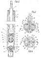
- Fig. 3 den Dämpferkolben eines Einrohr-Teleskop-Stoßdämpfers nach dem Schnitt III-III in Fig. 4, bei dem das erfindungsgemäße Ventilsystem in der Zug- und Druckstufe arbeitet;
- Fig. 4 eine Ansicht des Dämpfungskolbens nach Fig. 3 entsprechend der Schnittlinie IV-IV;
- Fig. 5 einen Dämpfungskolben eines Teleskopstoßdämpfers mit einem außermittig angeordneten federbelasteten Sitzventil;
- Fig. 6 zwei Ausführungsbeispiele, die links und rechts der Mittellinie dargestellt sind und
- Fig. 7 ein Ausführungsbeispiel, das drei Einstellungsstufen erlaubt.
- 1 shows a diagram with damping characteristics.
- 2 shows a two-tube telescopic shock absorber in which the valve system according to the invention is implemented both in the damper piston and as a bottom valve;
- 3 shows the damper piston of a monotube telescopic shock absorber according to section III-III in FIG. 4, in which the valve system according to the invention operates in the rebound and compression stages;
- Fig. 4 is a view of the damping piston of Figure 3 along the section line IV-IV.
- 5 shows a damping piston of a telescopic shock absorber with an eccentrically arranged spring-loaded seat valve;
- Fig. 6 shows two embodiments, which are shown to the left and right of the center line and
- Fig. 7 shows an embodiment that allows three adjustment levels.
Der Kurvenverlauf nach Fig. 1 ist im Anschluß an die Figurenbeschreibung erläutert. Außerdem tragen in den einzelnen Ausführungsbeispielen die sich einander gleichenden Bauteile die gleichen Bezugszeichen.1 is explained following the description of the figures. In addition, in the individual exemplary embodiments, the components that are identical to one another have the same reference symbols.
Fig. 2 läßt einen steuerbaren, hydraulischen Schwingungsdämpfer erkennen, wie er üblicherweise bei Radaufhängungen von Kraftfahrzeugen verwendet wird. Der Stoßdämpfer weist ein äußeres Mantelrohr 1 und ein konzentrisch darin angeordnetes inneres Mantelrohr 2 auf. Die beiden Mantelrohre 1 und 2 sind durch ein Bodenteil 3 und einem Verschlußstück 4 miteinander verbunden. In seinem Inneren nimmt das Mantelrohl 2 eine hohle Kolbenstange 5 auf, die an ihrem eingetauchten Ende über ein an ihr befestigtem, hülsenförmigem Zwischenstück 6 einen Dämpferkolben 7 trägt. Der Dämpferkolben 7 trennt den Innenraum des Mantelrohres 2 in eine erste Arbeitskammer 8 und eine zweite Arbeitskammer 9. Außerdem bildet sich zwischen dem äußeren Mantelrohr 1 und dem inneren Mantelrohr 2 eine Ausgleichskammer 10 aus.Fig. 2 shows a controllable, hydraulic vibration damper, as is usually used in wheel suspensions of motor vehicles. The shock absorber has an
Die Kolbenstange 5 bzw. der Dämpfungskolben 7 sind einmal geführt an der Innenwandung des Mantelrohres 2 und zum anderen im Verschlußstück 4. Schließlich füllt ein hydraulisches Dämpfungsmedium die Arbeitskammern 8 und 9 teilweise auch die Ausgleichskammer 10 aus. Soweit beschrieben, handelt es sich um einen herkömmlichen Stoßdämpfer, eine noch genauere Beschreibung bedarf es deshalb nicht.The
Innerhalb des Zwischenstückes 6 sitzt axial verdrehbar eine Steuerhülse 11, die zusammen mit dem Zwischenstück 6 bzw. dem Mantel der Kolbenstange 5 ein Schieberventil bildet. Zu diesem Zweck weisen die Bauteile an ihren Wandungen korrespondierende Querbohrungen 12 auf, die den Durchfluß von Dämpfungsflüssigkeit von der Arbeitskammer 8 über den Dämpferkolben 7 zur Arbeitskammer 9 ermöglichen. Durch Verdrehen verschließt die Steuerhülse 11 diese Querflußbohrungen 12. Dabei geschieht dies über einen ebenfalls in der Kolbenstange angeordneten Stellmotor 13, der über ein Untersetzungsgetriebe 14 auf die Steuerhülse 11 wirkt.A
An dem Zwischenstück 6 ist an einem unteren, abgesetzen und rohrförmigen Abschnitt der Dämpferkolben 7 befestigt. Dabei führt eine Durchtrittsöffnung 15 in der Wandung des Zwischenstücks 6 zu einem Kanal 16, der innerhalb des Dämpferkolbens 7 schräg nach unten und außen verläuft. Er mündet auf ein federbelastetes Sitzventil 17, das aus einem mittig eingespannten Scheibenfederpaket besteht. Auf der anderen Seite durchzieht ein weiterer Durchflußkanal 18 den Dämpferkolben 7. Dieser Durchflußkanal 18 öffnet sich in Richtung der Arbeitskammer 8 und trifft ebenso wie der Kanal 16 auf das Federpaket des Sitzventils 17, allerdings in einem geringeren radialen Abstand zur Einspannstelle.On the
Im Sinne der Erfindung bilden die Querbohrungen 12 und die Durchtrittsöffnung 15 sowie der Weg zwischen ihnen in dem Zwischenstück 6 und der Kanal 16 den Bypass-Kanal, während der Kanal 18 als der offene Durchflußkanal anzusehen ist. Das so beschriebene Ventilsystem arbeitet, wie noch näher dargelegt, in der Zugstufe, also wenn die Kolbenstange 5 nach oben gezogen wird.In the sense of the invention, the transverse bores 12 and the
Ein ähnliches Ventilsystem ist im Bodenteil 3 vorgesehen für die Druckstufe. Es ist wieder eine entsprechende Steuernadel 11' erkennbar, die sich über einen Motor 13' und Getriebe 14' axial verdrehen läßt. Außerdem geben Querbohrungen 12' in der Hülse 6' den Weg zu einem Sitzventil 17' frei. Auf dieses Sitzventil 17' wirkt schließlich auch ein vergleichbarer Durchflußkanal 18'.A similar valve system is provided in the
Eine nicht näher dargestellte Auswertelektronik steuert den Stellmotor 13, durch den die Steuerhülse 11 entweder die Querbohrungen 12 freigibt oder verschließt. Bei verschlossenen Querbohrungen 12 weist der Stoßdämpfer seine harte Einstellung auf. Wird in diesem Fall die Kolbenstange 5 herausgezogen, fließt über den offenen Durchflußkanal 18 Dämpfungsflüssigkeit von der Arbeitskammer 8 in die Arbeitskammer 9. Um das Sitzventil 17 zu öffnen, bedarf es eines bestimmten Druckes der Dämpfungsflüssigkeit, der wiederum von der Geschwindigkeit abhängt, mit der der Dämpfungskolben 17 nach oben gezogen wird.An evaluation electronics, not shown, controls the
Diese Schwelle wird gesenkt, wenn die Steuerhülse 11 die Querbohrungen 12 freigibt. Dann fließt außer im dem Durchflußkanal 18 auch Dämpfungsflüssigkeit durch den Bypass-Kanal und trifft am Ende des Kanalstücks 16 ebenfalls auf die Sitzfeder 17, allerdings in einem größeren radialen Abstand zur Einspannstelle. Durch den sich daraus ergebenden größeren Hebelarm vermag die Dämpfungsflüssigkeit im Bypass-Kanal das Abheben des Federpakets schon bei einem geringeren Druck zu bewirken. Außerdem ergibt sich ein größerer Öffnungsspalt, so daß insgesamt mehr Dämpfungsflüssigkeit austreten kann. Der Stoßdämpfer ist in diesem Zustand weicher, er kann also schon bei kleineren Flüssigkeitsdrücken reagieren.This threshold is lowered when the
In der Zugstufe saugt der Stoßdämpfer außerdem durch die sich ergebende Volumenvergrößerung der Arbeitskammer 9 Dämpfungsflüssigkeit aus der Ausgleichskammer 10 über das Bodenventil in diese Arbeitskammer 9 hinein. Die Dämpfungsflüssigkeit fließt dabei durch einen Kanal 19, der ebenfalls auf ein mittig eingespanntes Scheibenfederpaket 20 führt. Dieser Durchfluß ist, wie die Fig. 2 zeigt, in seinem Volumenstrom nicht veränderbar. Es handelt sich dabei um herkömmliches Rückflußventil.In the rebound stage, the shock absorber also sucks damping fluid from the compensating
In der Druckstufe steuert das Ventilsystem in dem Bodenteil den Stoßdämpfer, d. h. je nachdem, ob die Steuernadel 11' die Durchflußöffnungen 12' freigibt oder verschließt, nimmt der Stoßdämpfer eine härtere oder weichere Charakterisik an. Das Ventilsystem arbeitet entsprechend dem in dem Dämpferkolben 7. Ergänzend sei in diesem Zusammenhang noch auf einen Kanal 21 im Dämpferkolben 7 hingewiesen, der wiederum über ein federbelastetes Sitzventil herkömmlicher Art den Austausch von Dämpfungsflüssigkeit zwischen den Arbeitskammern 9 und 8 während der Druckstufe ermöglicht.In the pressure stage, the valve system controls the shock absorber in the bottom part, ie depending on whether the control needle 11 'opens or closes the flow openings 12', the shock absorber assumes a harder or softer characteristic. The valve system operates in accordance with that in the
Das Ventilsystem nach Fig. 2 weist wenigstens im Bereich des Sitzventils 17 bzw. 17' auch einen Konstantdurchfluß auf, der jedoch im Zusammenhang mit Fig. 5 näher beschrieben wird.The valve system according to FIG. 2 also has a constant flow, at least in the area of the
In Fig. 3 und 4 ist der Dämpferkolben 7 eines Einrohr-Teleskop-Stoßdämpfers in einem gegenüber Fig. 2 vergrößerten Maßstab dargestellt. Das Zwischenstück, an dem der Dämpferkolben 7 befestigt ist, trägt hier die Bezugsziffer 22. Innerhalb dieses Zwischenstückes 22 ist drehbar ein Steuerstift 23 gehalten, der eine konzentrische, nach unten offene Sackbohrung 24 aufweist. Im oberen Bereich der Sackbohrung 24 gehen Querbohrungen 12 ab, die mit entsprechenden Querbohrungen im Zwischenstück 22 fluchten. Auf halber Höhe führt eine weitere Durchflußbohrung 25 und eine entsprechenden Durchtrittsöffnung im Zwischenstück 22 zu einem Längskanal 26, der durch eine Innenwandung des Dämpferkolbens 7 und einer Außenwandung des Zwischenstückes 22 gebildet ist. Der Längskanal 26 führt zu konzentrisch um das Zwischenstück 22 verlaufenden Ringkanälen 27, 28, die die Verbindung zu mehreren, an der Unterseite und Oberseite des Ringkolbens 7 ausgebildeten, taschenförmigen Ausnehmungen 29, 30 herstellen. Diese taschenförmigen Ausnehmungen werden von den Federpaketen von Sitzventilen 31 und 32 überdeckt. Die Sacklochbohrung 24 erweitert sich in ihrem mittleren Abschnitt im Bereich der Durchflußbohrung 25 und nimmt zwei als Kegelspitzen ausgebildete Ventilkörper 33, 34 auf. Diese Ventilkörper 33, 34 verschließen symmetrisch zur Durchflußöffnung 25 die Sacklochbohrung 24 nach oben und nach unten. Dabei werden sie von einer Druckfeder 35 auf ihre Ventilsitze gepreßt.3 and 4, the
Neben diesem Kanalsystem weist der Dämpferkolben noch zwei Arten von schräg verlaufenden Durchflußkanälen auf wobei die einen mit 36 und die anderen mit 37 bezeichnet sind. Die Durchflußkanäle 36 weisen Konstantdurchflüsse 38 und die taschenförmigen Ausnehmungen 29 Konstantdurchflüsse 39 auf. Die Funktion der Konstantdurchflüsse wird, wie bereits erwähnt, anhand der Fig. 5 erklärt.In addition to this channel system, the damper piston also has two types of oblique flow channels, one designated 36 and the other 37. The
Durch seinen Aufbau ermöglicht das Ventilsystem nach Fig. 3 und 4 eine Steuerung der Dämpfungscharkteristik in der Zug- und Druckstufe. In der Zugstufe fließt die Dämpfungsflüssigkeit bei geschlossenen Querbohrungen 12 nur durch die Durchflußkanäle 36 auf das Sitzventil 31. Bei geöffnetem Bypass fließt daneben noch Dämpfungsflüssigkeit durch die Querbohrungen 12, Sacklochbohrung 24, Durchflußbohrung 25, Längskanal 26 und Ringkanal 27 in die Ausnehmungen 31. Dabei drückt sie den Ventilkörper 34 in die Offenstellung, während der Ventilkörper 33 auf seinen Ventilsitz gepreßt wird. Durch die taschenförmige Ausnehmungen ergeben sich große Durckflächen auf dem Scheibenfederpaket des Sitzventils 31, was wiederum zur Folge hat, daß dieses Sitzventil bereits bei niedrigen Drücken öffnet.Due to its construction, the valve system according to FIGS. 3 and 4 enables control of the damping characteristics in the rebound and compression stages. In the rebound stage, the damping fluid only flows through the
In der Druckstufe fließt die Dämpfungsflüssigkeit in umgekehrter Richtung durch den Durchflußkanal 37 und tritt außerdem in das offene Ende der Sacklochbohrung 24, sofern der Steuerstift 23 die Querbohrungen 12 auf Durchgang geschaltet hat. In diesem Fall hebt die Dämpfungsflüssigkeit den Ventilkörper 13 von seinem Sitz ab und preßt dagegen den Ventilkörper 34 in die Schließstellung. Die Dämpfungsflüssigkeit fließt über Durchflußbohrung 25, Längskanal 26 und Ringkanal 28 in die taschenförmigen Ausnehmungen 30. Ansonsten wirkt das Ventilsystem in der Zug- und Druckstufe in vergleichbarer Weise.In the pressure stage, the damping liquid flows in the opposite direction through the
Die Ausführung nach Fig. 5 ist mit der nach Fig. 2 vergleichbar. Der wesentliche Unterschied besteht lediglich in der Ausbildung des Sitzventils, das hier mit 40 bezeichnet ist. Das Sitzventil 40 besteht aus einer außermittig angeordneten Ventilplatte 41, die eine Druckfeder 42 gegen ihren Sitz an der Unterseite des Ventilkörpers 7 preßt. Durch die außermittige Anordnung erhält man wiederum einen vergleichsweise kleinen, radialen Abstand des hier senkrecht angeordneten Durchflußkanales 18 zu der Kraftwirkungslinie der Druckfeder 42. Der schräg nach unten laufende Kanal 16, als Teil des Bypass-Kanals, mündet dagegen in einem größeren, radialen Abstand auf die Ventilplatte 41. Durch diese Anordnung erhält man wieder eine harte Einstellung wenn die Steuerhülse 11, die hier mit einem Schaft verbunden ist, den Bypass versperrt und eine weiche Einstellung, wenn sie ihn freigibt.5 is comparable to that of FIG. 2. The main difference is only the design of the seat valve, which is designated 40 here. The
Zwischen der Austrittsöffnung des Durchflußkanals 18 und der Oberseite der Ventilplatte 41 ist eine nicht verschließbare Konstantdurchflußöffnung 43 vorgesehen. Eine ähnliche Durchflußöffnung 44 bildet sich zwischen dem Kanal 16 und der Ventilplatte 41 aus.A non-closable constant flow opening 43 is provided between the outlet opening of the
Diese Konstantdurchflüsse 43, 44 ermöglichen einen Durchsatz von Dämpfungsflüssigkeit auch dann, wenn das Sitzventil bzw. die Ventilplatte 41 noch nicht abgehoben hat. Dadurch wird erreicht, daß selbst bei geringen Kräften der Dämpfungskolben 7 bereits Dämpfungsflüssigkeit über diese Konstantdurchflüsse 43, 44 verdrängen und sich somit nach oben bewegen kann. Durch die wahlweise Möglichkeit des Öffnen oder Verschließen des Bypass-Kanales kann auch die Durchflußmenge der Dämpfungsflüssigkeit variiert werden. Damit läßt das Ventilsystem auch schon eine härtere und weichere Einstellung zu bei Kolbengeschwindigkeiten, bei denen das Sitzventil 40 noch nicht geöffnet hat.These constant flows 43, 44 enable a throughput of damping liquid even when the seat valve or the
Fig. 6 beinhaltet zwei Ausführungsbeispiele, die sich jedoch weitgehend gleichen. Die hauptsächlichen Unterschiede bestehen darin, daß das Schieberventil, das den Bypass-Kanal schließt, auf der linken Bildhälfte als Drehschieber 45 und auf der rechten Bildhälfte als Axialschieber 46 ausgebildet ist. Das Verschlußorgan des Sitzventiles ist in beiden Ausführungen in zwei ineinander angeordnete, topfförmige Bauteile getrennt, die teleskopartig gegeneinander verschiebbar sind. Dabei übergreift das innere Bauteil 47 der linken Ausführung in radialer Richtung mit einem als Ventilplatte dienenden Flansch das äußere Bauteil 48. Außerdem weist dieser Flanschabschnitt eine auf einen Kragen des äußeren Bauteils 48 zielende Durchtrittsöffnung 49 auf. Außerdem stützt sich das innere Bauteil 47 mit seinem das äußere Bauteil 48 übergreifenden Randabschnitt an einer Schraubenfeder 50 ab, während der Kragenabschnitt des äußeren Bauteils 48 über eine Schraubenfeder 51 gegen die Unterseite des Flanschteiles des inneren Bauteils 47 gedrückt wird und dadurch die Durchtrittsöffnung 49 verschließt.6 contains two exemplary embodiments, which, however, are largely the same. The main differences are that the slide valve, which closes the bypass channel, is designed as a
Bei den topfförmigen Bauteilen der rechten Ausführung wird das äußere Bauteil 52 durch eine Druckfeder 53 gegen die Unterseite des Dämpfungskolbens 7 gedrückt. Das innere Bauteil 54 stützt sich dagegen über eine Druckfeder 55 am äußeren Bauteil 52 ab. Außerdem verschließt dieses Bauteil 54 einen Kanalabschnitt 56 des noch näher darzustellenden Bypass-Kanales.In the case of the pot-shaped components of the right-hand embodiment, the
Der Bypass-Kanal im Sinne der Erfindung wird wiederum gebildet durch Querbohrungen 12 in der Wandung einer hohlen Kolbenstange 57 und durch entsprechende Öffnungen in dem Drehschieber 45 bzw. einem aus Quer- und Axialbohrung gebildeten Kanalabschnitt 58 in dem Axialschieber 46. Ein Endstück 59, das in die Kolbenstange 57 eingeschraubt ist, bildet mit einer zentralen Durchgangsbohrung 60 einen weiteren Abschnitt des Bypass-Kanales. Von dieser Durchgangsbohrung gehen Querkanäle 61 ab, die beim linken Ausführungsbeispiel in die Durchtrittsöffnung 49 münden und bei dem rechten Ausführungsbeispiel in den Kanalabschnitt 56. Unterhalb der Querkanäle verschließt ein federbelastetes Rückschlagventil 62 die Durchgangsbohrung, die in diesem Abschnitt die Funktion eines Nebenarms des Bypass-Kanals darstellt.The bypass channel in the sense of the invention is in turn formed by
Ein Durchflußkanal 18 durchzieht in senkrechter Richtung den Dämpferkolben 7 und erweitert sich an der Oberseite zu einer größeren Aufnahmeöffnung. Der Durchflußkanal 18 ist nur in der linken Ausführung sichtbar; er ist aber entsprechenderweise auch in der rechten Ausführung vorgesehen. Das untere Ende des Durchflußkanales 18 verschließt links das innere Bauteil 47 mit seinem Radialflansch, rechts (und nicht erkennbar) das äußere Bauteil 52. Schließlich ist im Dämpferkolben 7 links noch eine schrägverlaufende Rückflußleitung 63 erkennbar, die wiederum in gleicher Weise auch rechts vorgesehen ist. Die Rückflußleitung 63 öffnet sich nach unten und ist an ihrem oberen Ende durch ein herkömmliches federbelastetes Plattenventil verschlossen.A
In der Zugstufe fließt Dämpfungsflüssigkeit durch den Durchflußkanal 18 und beaufschlagt im linken Ausführungsbeispiel das äußere Bauteil 47. Da aber das innere Bauteil 48 von unten an das äußere Bauteil 47 anstößt, muß der Druck in der Dämpfungsflüssigkeit so weit ansteigen, daß die Kraft beider Druckfedern 50 und 51 überwunden werden können. Bezüglich der Druckfedern 50, 51 handelt es sich hier demnach um eine Parallelschaltung. Hat der Drehschieber 45 geöffnet, fließt zusätzlich Dämpfungsflüssigkeit durch den Bypass-Kanal und beaufschlagt durch die Durchtrittsöffnung 49 das innere Bauteil 48. Die Parallelschaltung ist damit aufgehoben und bei entsprechender Dimensionierung der Druckfeder 51 gibt das Bauteil 48 schon bei verhältnisnmäßig geringen Drücken den Durchfluß durch den Bypass-Kanal frei.In the rebound damping fluid flows through the
Beim rechten Ausführungsbeispiel drückt bei geschlossenem Axialschieber die Dämpfungsflüssigkeit über den (hier nicht sichtbaren) Kanal 18 auf das äußere Bauteil 52. Bei geöffnetem Axialschieber 46 drückt die Dämpfungsflüssigkeit über den Bypass-Kanal zusätzlich auf das innere Bauteil 54, das wiederum über die Druckfeder 55 die Kraft an das äußere Bauteil 52 weitergibt. Hier liegt eine Serienschaltung der beiden Druckfedern 55 und 53 vor.In the right embodiment, when the axial slide is closed, the damping liquid presses on the
Die beiden Ausführungsbeispiele nach Fig. 6 erlauben aber auch eine Steuerung in der Druckstufe. Verschließt der Drehschieber 45 bzw. Axialschieber 46 den Bypass-Kanal, erfolgt der Flüssigkeitsaustausch in dieser Stufe über den Kanal 63. Bei geöffnetem Bypass-Kanal fließt jedoch zusätzlich Dämpfungsflüssigkeit durch die Durchgangsbohrung 60 über das Rückschlagventil 62 des Endstückes 59 in die obere Arbeitskammer. In diesem Fall erhält der Stoßdämpfer eine weichere Kennung.However, the two exemplary embodiments according to FIG. 6 also allow control in the pressure stage. If the
Die Fig. 7 zeigt einen Axialschieber 64, der als Stufenkolben ausgebildet und mit einem Ringbund 65 in einer hohlen Kolbenstange 66 eines Stoßdämpfers 67 geführt ist. Über das untere Ende der Kolbenstange 66 ist ein Dämpfungskolben 7 geschoben und dort befestigt. Der Dämpfungskolben 7 weist lediglich einen Rückflußkanal 68 auf, ansonsten ist das gesamte Ventilsystem innerhalb der Kolbenstange 66 angeordnet. Dadurch ergibt sich ein kompakter Aufbau.7 shows an
In der Kolbenstange 66 ist ein mit Durchflußkanälen 69, 70, 71 versehenes Mittelstück 72 unterhalb des Axialschiebers 64 befestigt. Gegen die Unterseite dieses Mittelstücks 72 drückt eine Schraubenfeder 73 einen hutförmiger Schließkörper 74, der dadurch den Durchflußkanal 69 verschließt. Innerhalb des hutförmigen Schließkörpers 74 ist axial verschiebbar ein Verschlußstopfen 75 angeordnet, der über eine sich am Boden des hutförmigen Schließkörpers 74 abstützende Druckfeder 76 gegen die Unterseite des Mittelstücks 72 gepreßt wird un dabei im wesentlichen die Durchflußkanäle 70 und 71 verschließt.In the
Der Axialschieber 64 weist an seinem unteren Ende einen dornförmigen Fortsatz 77 auf, der in den Durchflußkanal 71 einzutauchen und ihn zu verschließen vermag. Ein Absatz 78 oberhalb des Fortsatzes 77 ermöglicht es dem Axialschieber 64 bei genügender Eintauchtiefe, die Durchflußkanäle 70 zu verschließen.The
Durch diesen Aufbau läßt der Stoßdämpfer 67 in der Zugstufe 3 verschiedene Härteeinstellungen zu. Bei der härtesten Stufe ist der Axialschieber 64 voll eingefahren. Er verschließt damit den Durchflußkanal 71, die Durchflußkanäle 70 und mit seinem Ringbund 65 die Querbohrungen 12 in der Wand der Kolbenstange 66. Die Dämpfungsflüssigkeit kann lediglich durch die Kanäle 69 unter Überwindung der Federkraft 73 in die andere Arbeitskammer fließen.With this construction, the
In der zweiten Stellung, das ist die Stellung nach Fig.7, gibt der Ringbund 65 die Durchtrittsöffnungen 12 und der Absatz 78 die Durchflußkanäle 70 frei. Nun kann zusätzlich Dämpfungsflüssigkeit über die Durchflußkanäle 70 fließen, die einerseits den hutförmigen Schließkörper 74 und andererseits den Verschlußstopfen 75 beaufschlagen.In the second position, that is the position according to FIG. 7, the
In der dritten, weichsten Stufe, ist der Axialschieber 64 nach oben gefahren und gibt damit auch noch den Durchflußkanal 71 frei. Die durchströmende Dämpfungsflüssigkeit erhält so eine größere wirksame Druckfläche am Verschlußstopfen 75 gegenüber der zweiten Einstellung, und vermag ihn dadurch schon bei niedrigen Drücken zu bewegen.In the third, softest stage, the
Die prinzipielle Wirkungsweise bzw. die möglichen Verstellbereiche der beschriebenen Ausführungsbeispiele sollen nun noch einmal anhand der in Fig. 1 dargestellten Kennlinien aufgezeigt werden. Bei dem in dieser Figur dargestellten Diagramm ist auf der Abszisse 83 die Kolbengeschwindigkeit aufgetragen und auf der Ordinate 84 die Dämpfungskraft. Die Kurve d zeigt die Verhältnisse, wenn beispielsweise in Fig. 5 der Bypass-Kanal geschlossen und der Konstantdurchfluß 43 nicht vorhanden wäre, so daß (ohne Leckverluste) Dämpfungsflüssigkeit nur durch den Durchflußkanal 18 strömen kann. Es zeigt sich, daß die Dämpfkraft bis zu einem besimmten Wert, hier mit 79 bezeichnet, ansteigen muß, bevor das Sitzventil 40 öffnet. Unterhalb dieses Wertes ist wegen der Inkompressibilität der Dämpfungsflüssigkeit eine Bewegung des Dämpfungskolbens nicht möglich. Das heißt, geringe Kräfte die auf den Schwingungsdämpfer wirken, werden nicht abgebaut. Das führt zu Komforteinbußen.The basic mode of operation and the possible adjustment ranges of the exemplary embodiments described are now to be shown again on the basis of the characteristic curves shown in FIG. 1. In the diagram shown in this figure, the piston speed is plotted on the
Die Kurve b zeigt die Verhältnisse, wenn die Steuerhülse 11 nach Fig. 5 den Bypass-Kanal freigibt. Die Ansprechstufe liegt hier wesentlich tiefer und ist mit 80 bezeichnet. Durch die vorgestellten konstruktiven Variationsmöglichkeiten, die durch die getrennte Führung des Durchflußkanales und des Bypass-Kanales möglich sind läßt sich die Verschiebung der Kurve b in einem weiten Bereich vornehmen.Curve b shows the conditions when the
Die Kurve c gibt die Verhältnisse wieder, wenn beispielsweise die Ausführung nach Fig. 5 mit dem Konstantdurchfluß 43 versehen ist. Hier zeigt sich, daß bereits von Anfang an Dämpfungsflüssigkeit zwischen den einzelnen Arbeitskammern in der jeweiligen Stufe, Druck- oder Zugstufe, pulsieren kann. Der Dämpfungskolben verschiebt sich schon bei geringen, auf ihn einwirkenden Kräften, die z. B. aus den Wankbewegungen des Fahrzeugaufbaus herrühren. Es wird auf diese Weise eine Verbesserung des Komforts im Bereich unterhalb der Linie d oder b erreicht. Mit steigender Kolbengeschwindigkeit erhöht sich aber der Durchflußwiderstand der Dämpfungsflüssigkeit durch diesen Konstantdurchfluß 43 exponentiell. Ab dem Punkt 81 öffnet dann das Sitzventil 40 und der Verlauf wird im wesentlichen durch die Kurve d bestimmt.Curve c shows the situation when, for example, the embodiment according to FIG. 5 is provided with
Ist der Bypass-Kanal in Fig. 5 geöffnet, kommt neben den Konstantdurchfluß 43 noch der Konstantdurchfluß 44 hinzu. Dadurch wird die Kennlinie c weicher und es ergibt sich ein Verlauf wie er mit der Kurve e dargestellt ist. Das Sitzventil öffnet sich bei dieser Einstellung im Punkt 82. Da auch hier wiederum bei den einzelnen beschriebenen Ausführungsbeispielen für die Konstantdurchflüsse eine große Freiheit an Gestaltungsmöglichkeiten gegeben ist, läßt sich auch der Verlauf der Kurve in einem weiten Bereich variieren.If the bypass channel in FIG. 5 is open, in addition to the
Claims (14)
Applications Claiming Priority (2)
| Application Number | Priority Date | Filing Date | Title |
|---|---|---|---|
| DE3523628 | 1985-07-02 | ||
| DE19853523628 DE3523628A1 (en) | 1985-07-02 | 1985-07-02 | VALVE SYSTEM FOR CONTROLLABLE, HYDRAULIC VIBRATION DAMPERS |
Publications (3)
| Publication Number | Publication Date |
|---|---|
| EP0207409A2 true EP0207409A2 (en) | 1987-01-07 |
| EP0207409A3 EP0207409A3 (en) | 1987-09-02 |
| EP0207409B1 EP0207409B1 (en) | 1990-02-07 |
Family
ID=6274752
Family Applications (1)
| Application Number | Title | Priority Date | Filing Date |
|---|---|---|---|
| EP86108485A Expired - Lifetime EP0207409B1 (en) | 1985-07-02 | 1986-06-21 | Valve system for an adjustable hydraulic damper |
Country Status (2)
| Country | Link |
|---|---|
| EP (1) | EP0207409B1 (en) |
| DE (2) | DE3523628A1 (en) |
Cited By (48)
| Publication number | Priority date | Publication date | Assignee | Title |
|---|---|---|---|---|
| EP0174119A2 (en) * | 1984-09-04 | 1986-03-12 | General Motors Corporation | Hydraulic damping unit |
| EP0294952A2 (en) * | 1987-06-08 | 1988-12-14 | General Motors Corporation | Hydraulic double-acting damper |
| FR2618507A1 (en) * | 1987-07-21 | 1989-01-27 | Sirven Jacques | HYDRAULIC SHOCK ABSORBER PROVIDED WITH MEANS FOR VARYING THE OPERATING CHARACTERISTICS |
| EP0305382A1 (en) * | 1987-03-18 | 1989-03-08 | Monroe Auto Equipment Co | Method and apparatus for absorbing mechanical shock. |
| EP0221602B1 (en) * | 1985-11-05 | 1989-05-31 | Koni B.V. | Electrically adjustable shock absorber |
| US4872537A (en) * | 1988-06-06 | 1989-10-10 | Brian Warner | Adjustable damper means for shock absorber |
| GB2223291A (en) * | 1988-08-02 | 1990-04-04 | Atsugi Motor Parts Co Ltd | Shock absorber with variable damping |
| FR2643961A1 (en) * | 1989-03-03 | 1990-09-07 | Maremont Corp | VARIABLE DAMPING SHOCK ABSORBER AND REMOTE CONTROL FOR MOTOR VEHICLES |
| US4964492A (en) * | 1988-02-26 | 1990-10-23 | S.A.M.M.-Societe D'applications Des Machines Motrices | Damper for a hydropneumatic suspension element of a vehicle, and in particular a heavy vehicle |
| GB2230584A (en) * | 1989-02-22 | 1990-10-24 | Atsugi Unisia Corp | Variable damping force shock absorber |
| US5018608A (en) * | 1989-05-19 | 1991-05-28 | Tokico Ltd. | Hydraulic shock absorber |
| EP0435357A1 (en) * | 1989-12-22 | 1991-07-03 | AUGUST BILSTEIN GMBH & CO. KG | Bypass valve with variable characteristics for adjustable vibration damper |
| US5072812A (en) * | 1989-01-10 | 1991-12-17 | Tokico Ltd. | Hydraulic shock absorber |
| US5226512A (en) * | 1989-02-22 | 1993-07-13 | Atsugi Unisia Corporation | Variable damping force shock absorber with variable orifice for adjusting damping characteristics |
| US5277283A (en) * | 1988-09-19 | 1994-01-11 | Atsugi Unisia Corporation | Variable damping-characteristics shock absorber with adjustable orifice construction variable of fluid flow restriction depending upon fluid pressure difference |
| US5305860A (en) * | 1989-03-03 | 1994-04-26 | Maremont Corporation | Remote controlled vehicle damper |
| DE19542409A1 (en) * | 1995-11-14 | 1997-05-15 | Industrieanlagen Betriebsges | Adjustable suspension damper |
| WO2006125624A1 (en) * | 2005-05-27 | 2006-11-30 | Daimlerchrysler Ag | Device and method for influencing the damping characteristics of the chassis suspension of a motor vehicle |
| WO2006125626A1 (en) * | 2005-05-27 | 2006-11-30 | Daimlerchrysler Ag | Device and method for influencing the damping characteristics of the chassis suspension of a motor vehicle |
| US20110203889A1 (en) * | 2010-02-22 | 2011-08-25 | Tae Woong Eom | Assembly and disassembly-type damping force adjustable shock absorber |
| WO2013143073A1 (en) * | 2012-03-27 | 2013-10-03 | Beijingwest Industries Co., Ltd. | Amplitude sensitive hydraulic damper |
| US20130313056A1 (en) * | 2012-05-10 | 2013-11-28 | Fox Factory, Inc. | Method and apparatus for an adjustable damper |
| EP2521867A4 (en) * | 2010-11-29 | 2017-06-21 | BeijingWest Industries Co. Ltd. | Hydraulic damper assembly |
| US9784333B2 (en) | 2009-01-07 | 2017-10-10 | Fox Factory, Inc. | Compression isolator for a suspension damper |
| US10036443B2 (en) | 2009-03-19 | 2018-07-31 | Fox Factory, Inc. | Methods and apparatus for suspension adjustment |
| US10040329B2 (en) | 2009-01-07 | 2018-08-07 | Fox Factory, Inc. | Method and apparatus for an adjustable damper |
| US10047817B2 (en) | 2009-01-07 | 2018-08-14 | Fox Factory, Inc. | Method and apparatus for an adjustable damper |
| US10060499B2 (en) | 2009-01-07 | 2018-08-28 | Fox Factory, Inc. | Method and apparatus for an adjustable damper |
| US10072724B2 (en) | 2008-08-25 | 2018-09-11 | Fox Factory, Inc. | Methods and apparatus for suspension lock out and signal generation |
| US10086670B2 (en) | 2009-03-19 | 2018-10-02 | Fox Factory, Inc. | Methods and apparatus for suspension set up |
| US10094443B2 (en) | 2009-01-07 | 2018-10-09 | Fox Factory, Inc. | Bypass for a suspension damper |
| US10160511B2 (en) | 2009-01-07 | 2018-12-25 | Fox Factory, Inc. | Method and apparatus for an adjustable damper |
| US10406883B2 (en) | 2009-10-13 | 2019-09-10 | Fox Factory, Inc. | Methods and apparatus for controlling a fluid damper |
| US10415662B2 (en) | 2009-01-07 | 2019-09-17 | Fox Factory, Inc. | Remotely operated bypass for a suspension damper |
| US10443671B2 (en) | 2009-01-07 | 2019-10-15 | Fox Factory, Inc. | Remotely operated bypass for a suspension damper |
| US10556477B2 (en) | 2009-01-07 | 2020-02-11 | Fox Factory, Inc. | Suspension damper with by-pass valves |
| US10591015B2 (en) | 2009-03-19 | 2020-03-17 | Fox Factory, Inc. | Methods and apparatus for suspension adjustment |
| US10677309B2 (en) | 2011-05-31 | 2020-06-09 | Fox Factory, Inc. | Methods and apparatus for position sensitive suspension damping |
| US10697514B2 (en) | 2010-01-20 | 2020-06-30 | Fox Factory, Inc. | Remotely operated bypass for a suspension damper |
| US10731724B2 (en) | 2009-10-13 | 2020-08-04 | Fox Factory, Inc. | Suspension system |
| US10737546B2 (en) | 2016-04-08 | 2020-08-11 | Fox Factory, Inc. | Electronic compression and rebound control |
| US10821795B2 (en) | 2009-01-07 | 2020-11-03 | Fox Factory, Inc. | Method and apparatus for an adjustable damper |
| US11021204B2 (en) | 2008-11-25 | 2021-06-01 | Fox Factory, Inc. | Seat post |
| US11279199B2 (en) | 2012-01-25 | 2022-03-22 | Fox Factory, Inc. | Suspension damper with by-pass valves |
| US11299233B2 (en) | 2009-01-07 | 2022-04-12 | Fox Factory, Inc. | Method and apparatus for an adjustable damper |
| US11306798B2 (en) | 2008-05-09 | 2022-04-19 | Fox Factory, Inc. | Position sensitive suspension damping with an active valve |
| US11413924B2 (en) | 2009-03-19 | 2022-08-16 | Fox Factory, Inc. | Methods and apparatus for selective spring pre-load adjustment |
| US11866110B2 (en) | 2010-07-02 | 2024-01-09 | Fox Factory, Inc. | Lever assembly for positive lock adjustable seat post |
Families Citing this family (5)
| Publication number | Priority date | Publication date | Assignee | Title |
|---|---|---|---|---|
| DE3532292C2 (en) * | 1985-09-11 | 1994-05-11 | Fichtel & Sachs Ag | Vibration damper with adjustable damping force |
| DE3824611A1 (en) * | 1988-07-20 | 1990-01-25 | Bayerische Motoren Werke Ag | SPRING-DAMPER SYSTEM FOR VEHICLES |
| AU614873B2 (en) * | 1988-09-19 | 1991-09-12 | Atsugi Unisia Corporation | Variable damping-characteristics shock absorber with adjustable orifice construction variable of fluid flow restriction depending upon fluid pressure difference |
| DE102014203842A1 (en) * | 2014-03-03 | 2015-09-03 | Zf Friedrichshafen Ag | Valve, in particular for a vibration damper |
| DE102019200205B4 (en) * | 2019-01-10 | 2022-08-18 | Zf Friedrichshafen Ag | Vibration damper with a sensor device |
Citations (10)
| Publication number | Priority date | Publication date | Assignee | Title |
|---|---|---|---|---|
| NL97561C (en) * | 1953-05-18 | 1900-01-01 | ||
| US2695034A (en) * | 1951-06-29 | 1954-11-23 | Gen Motors Corp | Shock absorber valve |
| DE1021653B (en) * | 1954-04-27 | 1957-12-27 | Siemens Ag | Adjustment device for a part guided by a freely oscillating spring, e.g. Contact part or valve disc |
| US3421606A (en) * | 1965-12-14 | 1969-01-14 | Citroen Sa Andre | Load-responsive hydraulic shock absorbers |
| US3568711A (en) * | 1967-06-29 | 1971-03-09 | Maurice Katz | Vehicle shock absorbers |
| FR2301737A1 (en) * | 1975-02-22 | 1976-09-17 | Blazquez Antonio Giner | IMPROVEMENTS TO DOUBLE ACTING HYDRAULIC SHOCK ABSORBERS |
| JPS57173629A (en) * | 1981-04-17 | 1982-10-26 | Kayaba Ind Co Ltd | Hydraulic buffer |
| GB2159917A (en) * | 1984-06-09 | 1985-12-11 | Boge Gmbh | An hydraulic damper with adjustable valve |
| EP0174119A2 (en) * | 1984-09-04 | 1986-03-12 | General Motors Corporation | Hydraulic damping unit |
| EP0196030A2 (en) * | 1985-03-22 | 1986-10-01 | Toyota Jidosha Kabushiki Kaisha | Hydraulic buffer |
Family Cites Families (5)
| Publication number | Priority date | Publication date | Assignee | Title |
|---|---|---|---|---|
| DE1063859B (en) * | 1954-03-03 | 1959-08-20 | Arie Adrianus De Koning | Shock absorbers |
| FR1130621A (en) * | 1955-09-01 | 1957-02-07 | Shock absorber for land vehicles | |
| DE3418327A1 (en) * | 1984-05-17 | 1985-11-21 | Peter BÄSSLER | Fully automatic light switch, controlled by a photoresistor, for motor vehicles |
| DE3421601A1 (en) * | 1984-06-09 | 1985-12-19 | Boge Gmbh, 5208 Eitorf | Adjustable hydraulic shock absorber |
| SE445850B (en) * | 1984-12-07 | 1986-07-21 | Magnus Lizell | PRESSURE VALVE DEVICE FOR PRESSURE MEDIA Separately for Hydraulic Oil in Vehicle Shock Absorbers and Similar |
-
1985
- 1985-07-02 DE DE19853523628 patent/DE3523628A1/en active Granted
-
1986
- 1986-06-21 EP EP86108485A patent/EP0207409B1/en not_active Expired - Lifetime
- 1986-06-21 DE DE8686108485T patent/DE3668964D1/en not_active Expired - Lifetime
Patent Citations (10)
| Publication number | Priority date | Publication date | Assignee | Title |
|---|---|---|---|---|
| US2695034A (en) * | 1951-06-29 | 1954-11-23 | Gen Motors Corp | Shock absorber valve |
| NL97561C (en) * | 1953-05-18 | 1900-01-01 | ||
| DE1021653B (en) * | 1954-04-27 | 1957-12-27 | Siemens Ag | Adjustment device for a part guided by a freely oscillating spring, e.g. Contact part or valve disc |
| US3421606A (en) * | 1965-12-14 | 1969-01-14 | Citroen Sa Andre | Load-responsive hydraulic shock absorbers |
| US3568711A (en) * | 1967-06-29 | 1971-03-09 | Maurice Katz | Vehicle shock absorbers |
| FR2301737A1 (en) * | 1975-02-22 | 1976-09-17 | Blazquez Antonio Giner | IMPROVEMENTS TO DOUBLE ACTING HYDRAULIC SHOCK ABSORBERS |
| JPS57173629A (en) * | 1981-04-17 | 1982-10-26 | Kayaba Ind Co Ltd | Hydraulic buffer |
| GB2159917A (en) * | 1984-06-09 | 1985-12-11 | Boge Gmbh | An hydraulic damper with adjustable valve |
| EP0174119A2 (en) * | 1984-09-04 | 1986-03-12 | General Motors Corporation | Hydraulic damping unit |
| EP0196030A2 (en) * | 1985-03-22 | 1986-10-01 | Toyota Jidosha Kabushiki Kaisha | Hydraulic buffer |
Non-Patent Citations (1)
| Title |
|---|
| W. BEITZ et al.: "TASCHENBUCH MASCHINENBAU", 14. Auflage, 1981, Springer, Berlin, DE * |
Cited By (100)
| Publication number | Priority date | Publication date | Assignee | Title |
|---|---|---|---|---|
| EP0174119A3 (en) * | 1984-09-04 | 1987-08-12 | General Motors Corporation | Hydraulic damping unit |
| EP0174119A2 (en) * | 1984-09-04 | 1986-03-12 | General Motors Corporation | Hydraulic damping unit |
| EP0221602B1 (en) * | 1985-11-05 | 1989-05-31 | Koni B.V. | Electrically adjustable shock absorber |
| EP0305382A1 (en) * | 1987-03-18 | 1989-03-08 | Monroe Auto Equipment Co | Method and apparatus for absorbing mechanical shock. |
| EP0305382A4 (en) * | 1987-03-18 | 1991-05-15 | Monroe Auto Equipment Company | Method and apparatus for absorbing mechanical shock |
| EP0294952A3 (en) * | 1987-06-08 | 1989-12-06 | General Motors Corporation | Hydraulic double-acting damper |
| EP0294952A2 (en) * | 1987-06-08 | 1988-12-14 | General Motors Corporation | Hydraulic double-acting damper |
| FR2618507A1 (en) * | 1987-07-21 | 1989-01-27 | Sirven Jacques | HYDRAULIC SHOCK ABSORBER PROVIDED WITH MEANS FOR VARYING THE OPERATING CHARACTERISTICS |
| EP0304599A1 (en) * | 1987-07-21 | 1989-03-01 | Jacques Sirven | Hydraulic shock absorber equipped with means for varying the damping characteristics |
| US4972928A (en) * | 1987-07-21 | 1990-11-27 | Sirven Jacques M M | Hydraulic damper with variable operating characteristics |
| US4964492A (en) * | 1988-02-26 | 1990-10-23 | S.A.M.M.-Societe D'applications Des Machines Motrices | Damper for a hydropneumatic suspension element of a vehicle, and in particular a heavy vehicle |
| US4872537A (en) * | 1988-06-06 | 1989-10-10 | Brian Warner | Adjustable damper means for shock absorber |
| US5293971A (en) * | 1988-08-02 | 1994-03-15 | Atsugi Unisia Corporation | Shock absorber with damping valve structure having wide range variable damping characteristics |
| GB2223291B (en) * | 1988-08-02 | 1992-08-19 | Atsugi Motor Parts Co Ltd | Shock absorbers and damping valve assemblies |
| GB2223291A (en) * | 1988-08-02 | 1990-04-04 | Atsugi Motor Parts Co Ltd | Shock absorber with variable damping |
| US5277283A (en) * | 1988-09-19 | 1994-01-11 | Atsugi Unisia Corporation | Variable damping-characteristics shock absorber with adjustable orifice construction variable of fluid flow restriction depending upon fluid pressure difference |
| US5072812A (en) * | 1989-01-10 | 1991-12-17 | Tokico Ltd. | Hydraulic shock absorber |
| GB2230584A (en) * | 1989-02-22 | 1990-10-24 | Atsugi Unisia Corp | Variable damping force shock absorber |
| US5226512A (en) * | 1989-02-22 | 1993-07-13 | Atsugi Unisia Corporation | Variable damping force shock absorber with variable orifice for adjusting damping characteristics |
| GB2230584B (en) * | 1989-02-22 | 1993-02-03 | Atsugi Unisia Corp | Variable damping force shock absorber with variable orifice for adjusting damping characteristics |
| US5305860A (en) * | 1989-03-03 | 1994-04-26 | Maremont Corporation | Remote controlled vehicle damper |
| BE1003010A4 (en) * | 1989-03-03 | 1991-10-22 | Maremont Corp | REMOTE CONTROL VEHICLE SHOCK ABSORBER. |
| FR2643961A1 (en) * | 1989-03-03 | 1990-09-07 | Maremont Corp | VARIABLE DAMPING SHOCK ABSORBER AND REMOTE CONTROL FOR MOTOR VEHICLES |
| US5018608A (en) * | 1989-05-19 | 1991-05-28 | Tokico Ltd. | Hydraulic shock absorber |
| EP0435357A1 (en) * | 1989-12-22 | 1991-07-03 | AUGUST BILSTEIN GMBH & CO. KG | Bypass valve with variable characteristics for adjustable vibration damper |
| DE19542409A1 (en) * | 1995-11-14 | 1997-05-15 | Industrieanlagen Betriebsges | Adjustable suspension damper |
| WO2006125624A1 (en) * | 2005-05-27 | 2006-11-30 | Daimlerchrysler Ag | Device and method for influencing the damping characteristics of the chassis suspension of a motor vehicle |
| WO2006125626A1 (en) * | 2005-05-27 | 2006-11-30 | Daimlerchrysler Ag | Device and method for influencing the damping characteristics of the chassis suspension of a motor vehicle |
| US11306798B2 (en) | 2008-05-09 | 2022-04-19 | Fox Factory, Inc. | Position sensitive suspension damping with an active valve |
| US10072724B2 (en) | 2008-08-25 | 2018-09-11 | Fox Factory, Inc. | Methods and apparatus for suspension lock out and signal generation |
| US11162555B2 (en) | 2008-08-25 | 2021-11-02 | Fox Factory, Inc. | Methods and apparatus for suspension lock out and signal generation |
| US10550909B2 (en) | 2008-08-25 | 2020-02-04 | Fox Factory, Inc. | Methods and apparatus for suspension lock out and signal generation |
| US11021204B2 (en) | 2008-11-25 | 2021-06-01 | Fox Factory, Inc. | Seat post |
| US11897571B2 (en) | 2008-11-25 | 2024-02-13 | Fox Factory, Inc. | Seat post |
| US10556477B2 (en) | 2009-01-07 | 2020-02-11 | Fox Factory, Inc. | Suspension damper with by-pass valves |
| US11168758B2 (en) | 2009-01-07 | 2021-11-09 | Fox Factory, Inc. | Method and apparatus for an adjustable damper |
| US10047817B2 (en) | 2009-01-07 | 2018-08-14 | Fox Factory, Inc. | Method and apparatus for an adjustable damper |
| US10060499B2 (en) | 2009-01-07 | 2018-08-28 | Fox Factory, Inc. | Method and apparatus for an adjustable damper |
| US12091122B2 (en) | 2009-01-07 | 2024-09-17 | Fox Factory, Inc. | Method and apparatus for an adjustable damper |
| US12044286B2 (en) | 2009-01-07 | 2024-07-23 | Fox Factory, Inc. | Compression isolator for a suspension damper |
| US10094443B2 (en) | 2009-01-07 | 2018-10-09 | Fox Factory, Inc. | Bypass for a suspension damper |
| US10160511B2 (en) | 2009-01-07 | 2018-12-25 | Fox Factory, Inc. | Method and apparatus for an adjustable damper |
| US11976706B2 (en) | 2009-01-07 | 2024-05-07 | Fox Factory, Inc. | Remotely operated bypass for a suspension damper |
| US10336148B2 (en) | 2009-01-07 | 2019-07-02 | Fox Factory, Inc. | Method and apparatus for an adjustable damper |
| US10336149B2 (en) | 2009-01-07 | 2019-07-02 | Fox Factory, Inc. | Method and apparatus for an adjustable damper |
| US10400847B2 (en) | 2009-01-07 | 2019-09-03 | Fox Factory, Inc. | Compression isolator for a suspension damper |
| US11890908B2 (en) | 2009-01-07 | 2024-02-06 | Fox Factory, Inc. | Method and apparatus for an adjustable damper |
| US10415662B2 (en) | 2009-01-07 | 2019-09-17 | Fox Factory, Inc. | Remotely operated bypass for a suspension damper |
| US10443671B2 (en) | 2009-01-07 | 2019-10-15 | Fox Factory, Inc. | Remotely operated bypass for a suspension damper |
| US9784333B2 (en) | 2009-01-07 | 2017-10-10 | Fox Factory, Inc. | Compression isolator for a suspension damper |
| US11866120B2 (en) | 2009-01-07 | 2024-01-09 | Fox Factory, Inc. | Method and apparatus for an adjustable damper |
| US10040329B2 (en) | 2009-01-07 | 2018-08-07 | Fox Factory, Inc. | Method and apparatus for an adjustable damper |
| US10670106B2 (en) | 2009-01-07 | 2020-06-02 | Fox Factory, Inc. | Method and apparatus for an adjustable damper |
| US11794543B2 (en) | 2009-01-07 | 2023-10-24 | Fox Factory, Inc. | Method and apparatus for an adjustable damper |
| US11660924B2 (en) | 2009-01-07 | 2023-05-30 | Fox Factory, Inc. | Method and apparatus for an adjustable damper |
| US10723409B2 (en) | 2009-01-07 | 2020-07-28 | Fox Factory, Inc. | Method and apparatus for an adjustable damper |
| US11549565B2 (en) | 2009-01-07 | 2023-01-10 | Fox Factory, Inc. | Method and apparatus for an adjustable damper |
| US11519477B2 (en) | 2009-01-07 | 2022-12-06 | Fox Factory, Inc. | Compression isolator for a suspension damper |
| US11499601B2 (en) | 2009-01-07 | 2022-11-15 | Fox Factory, Inc. | Remotely operated bypass for a suspension damper |
| US10781879B2 (en) | 2009-01-07 | 2020-09-22 | Fox Factory, Inc. | Bypass for a suspension damper |
| US10800220B2 (en) | 2009-01-07 | 2020-10-13 | Fox Factory, Inc. | Method and apparatus for an adjustable damper |
| US10807433B2 (en) | 2009-01-07 | 2020-10-20 | Fox Factory, Inc. | Method and apparatus for an adjustable damper |
| US10814689B2 (en) | 2009-01-07 | 2020-10-27 | Fox Factory, Inc. | Method and apparatus for an adjustable damper |
| US10821795B2 (en) | 2009-01-07 | 2020-11-03 | Fox Factory, Inc. | Method and apparatus for an adjustable damper |
| US11408482B2 (en) | 2009-01-07 | 2022-08-09 | Fox Factory, Inc. | Bypass for a suspension damper |
| US11299233B2 (en) | 2009-01-07 | 2022-04-12 | Fox Factory, Inc. | Method and apparatus for an adjustable damper |
| US11173765B2 (en) | 2009-01-07 | 2021-11-16 | Fox Factory, Inc. | Method and apparatus for an adjustable damper |
| US10591015B2 (en) | 2009-03-19 | 2020-03-17 | Fox Factory, Inc. | Methods and apparatus for suspension adjustment |
| US11413924B2 (en) | 2009-03-19 | 2022-08-16 | Fox Factory, Inc. | Methods and apparatus for selective spring pre-load adjustment |
| US12103349B2 (en) | 2009-03-19 | 2024-10-01 | Fox Factory, Inc. | Methods and apparatus for selective spring pre-load adjustment |
| US11655873B2 (en) | 2009-03-19 | 2023-05-23 | Fox Factory, Inc. | Methods and apparatus for suspension adjustment |
| US10036443B2 (en) | 2009-03-19 | 2018-07-31 | Fox Factory, Inc. | Methods and apparatus for suspension adjustment |
| US10086670B2 (en) | 2009-03-19 | 2018-10-02 | Fox Factory, Inc. | Methods and apparatus for suspension set up |
| US11619278B2 (en) | 2009-03-19 | 2023-04-04 | Fox Factory, Inc. | Methods and apparatus for suspension adjustment |
| US11920655B2 (en) | 2009-03-19 | 2024-03-05 | Fox Factory, Inc. | Methods and apparatus for suspension adjustment |
| US11859690B2 (en) | 2009-10-13 | 2024-01-02 | Fox Factory, Inc. | Suspension system |
| US10406883B2 (en) | 2009-10-13 | 2019-09-10 | Fox Factory, Inc. | Methods and apparatus for controlling a fluid damper |
| US10731724B2 (en) | 2009-10-13 | 2020-08-04 | Fox Factory, Inc. | Suspension system |
| US12005755B2 (en) | 2009-10-13 | 2024-06-11 | Fox Factory, Inc. | Methods and apparatus for controlling a fluid damper |
| US11279198B2 (en) | 2009-10-13 | 2022-03-22 | Fox Factory, Inc. | Methods and apparatus for controlling a fluid damper |
| US10697514B2 (en) | 2010-01-20 | 2020-06-30 | Fox Factory, Inc. | Remotely operated bypass for a suspension damper |
| US11708878B2 (en) | 2010-01-20 | 2023-07-25 | Fox Factory, Inc. | Remotely operated bypass for a suspension damper |
| US20110203889A1 (en) * | 2010-02-22 | 2011-08-25 | Tae Woong Eom | Assembly and disassembly-type damping force adjustable shock absorber |
| US11866110B2 (en) | 2010-07-02 | 2024-01-09 | Fox Factory, Inc. | Lever assembly for positive lock adjustable seat post |
| EP2521867A4 (en) * | 2010-11-29 | 2017-06-21 | BeijingWest Industries Co. Ltd. | Hydraulic damper assembly |
| US10677309B2 (en) | 2011-05-31 | 2020-06-09 | Fox Factory, Inc. | Methods and apparatus for position sensitive suspension damping |
| US11796028B2 (en) | 2011-05-31 | 2023-10-24 | Fox Factory, Inc. | Methods and apparatus for position sensitive suspension damping |
| US10759247B2 (en) | 2011-09-12 | 2020-09-01 | Fox Factory, Inc. | Methods and apparatus for suspension set up |
| US11958328B2 (en) | 2011-09-12 | 2024-04-16 | Fox Factory, Inc. | Methods and apparatus for suspension set up |
| US11760150B2 (en) | 2012-01-25 | 2023-09-19 | Fox Factory, Inc. | Suspension damper with by-pass valves |
| US11279199B2 (en) | 2012-01-25 | 2022-03-22 | Fox Factory, Inc. | Suspension damper with by-pass valves |
| WO2013143073A1 (en) * | 2012-03-27 | 2013-10-03 | Beijingwest Industries Co., Ltd. | Amplitude sensitive hydraulic damper |
| US9217484B2 (en) | 2012-03-27 | 2015-12-22 | Beijing West Industries | Amplitude sensitive hydraulic damper |
| US11629774B2 (en) | 2012-05-10 | 2023-04-18 | Fox Factory, Inc. | Method and apparatus for an adjustable damper |
| US20130313056A1 (en) * | 2012-05-10 | 2013-11-28 | Fox Factory, Inc. | Method and apparatus for an adjustable damper |
| US10330171B2 (en) * | 2012-05-10 | 2019-06-25 | Fox Factory, Inc. | Method and apparatus for an adjustable damper |
| US10859133B2 (en) | 2012-05-10 | 2020-12-08 | Fox Factory, Inc. | Method and apparatus for an adjustable damper |
| US12038062B2 (en) | 2012-05-10 | 2024-07-16 | Fox Factory, Inc. | Method and apparatus for an adjustable damper |
| US10737546B2 (en) | 2016-04-08 | 2020-08-11 | Fox Factory, Inc. | Electronic compression and rebound control |
| US11472252B2 (en) | 2016-04-08 | 2022-10-18 | Fox Factory, Inc. | Electronic compression and rebound control |
Also Published As
| Publication number | Publication date |
|---|---|
| DE3668964D1 (en) | 1990-03-15 |
| DE3523628C2 (en) | 1989-09-28 |
| EP0207409B1 (en) | 1990-02-07 |
| EP0207409A3 (en) | 1987-09-02 |
| DE3523628A1 (en) | 1987-01-15 |
Similar Documents
| Publication | Publication Date | Title |
|---|---|---|
| EP0207409B1 (en) | Valve system for an adjustable hydraulic damper | |
| DE10257872B4 (en) | Hydraulic shock absorber with damping force control | |
| DE4129581C2 (en) | Controllable valve arrangement for controllable two-pipe vibration dampers | |
| DE3321680C2 (en) | ||
| EP0400395B1 (en) | Shock absorber | |
| DE10126555C2 (en) | Damping force regulating hydraulic shock absorber | |
| DE19734522C2 (en) | Hydraulic shock absorber with adjustable damping force | |
| DE4019221C2 (en) | Shock absorbers with variable damping force | |
| DE10234906B4 (en) | Adjustment of the compression damping of a shock absorber | |
| DE19512866C2 (en) | Vibration damper | |
| DE4223673C2 (en) | Pressure actuated valve arrangement in the piston of a shock absorber | |
| EP0435357B1 (en) | Bypass valve with variable characteristics for adjustable vibration damper | |
| DE3532633C2 (en) | Hydraulic damper | |
| EP0318816A2 (en) | Hydraulic shock and vibration damper with adjustable damping | |
| EP0534075A1 (en) | Damping force regulation device for shock absorber | |
| DE3781147T2 (en) | ADJUSTABLE SHOCK ABSORBER. | |
| DE3724271A1 (en) | DAMPING DEVICE | |
| DE4022688C2 (en) | Conversely, installable shock absorbers with variable damping force and variable damping characteristics for both the forward stroke and the return stroke movements | |
| DE60133246T2 (en) | Solenoid valve stepless adjustable shock absorber | |
| EP1500845B1 (en) | Shock absorber with variable damping characteristics | |
| DE966497C (en) | In both directions working plate valve for fluid shock absorbers | |
| EP0599045A2 (en) | Controllable hydraulic shock absorber | |
| EP1106403B1 (en) | Adjustable vibration damper | |
| EP0504624A2 (en) | Shock absorber | |
| DE112019001113T5 (en) | Shock absorbers |
Legal Events
| Date | Code | Title | Description |
|---|---|---|---|
| PUAI | Public reference made under article 153(3) epc to a published international application that has entered the european phase |
Free format text: ORIGINAL CODE: 0009012 |
|
| AK | Designated contracting states |
Kind code of ref document: A2 Designated state(s): DE FR GB IT |
|
| PUAL | Search report despatched |
Free format text: ORIGINAL CODE: 0009013 |
|
| AK | Designated contracting states |
Kind code of ref document: A3 Designated state(s): DE FR GB IT |
|
| 17P | Request for examination filed |
Effective date: 19870724 |
|
| 17Q | First examination report despatched |
Effective date: 19880708 |
|
| GRAA | (expected) grant |
Free format text: ORIGINAL CODE: 0009210 |
|
| AK | Designated contracting states |
Kind code of ref document: B1 Designated state(s): DE FR GB IT |
|
| GBT | Gb: translation of ep patent filed (gb section 77(6)(a)/1977) | ||
| ET | Fr: translation filed | ||
| REF | Corresponds to: |
Ref document number: 3668964 Country of ref document: DE Date of ref document: 19900315 |
|
| ITF | It: translation for a ep patent filed | ||
| ITTA | It: last paid annual fee | ||
| PLBE | No opposition filed within time limit |
Free format text: ORIGINAL CODE: 0009261 |
|
| STAA | Information on the status of an ep patent application or granted ep patent |
Free format text: STATUS: NO OPPOSITION FILED WITHIN TIME LIMIT |
|
| 26N | No opposition filed | ||
| PGFP | Annual fee paid to national office [announced via postgrant information from national office to epo] |
Ref country code: DE Payment date: 19930605 Year of fee payment: 8 |
|
| PGFP | Annual fee paid to national office [announced via postgrant information from national office to epo] |
Ref country code: GB Payment date: 19930621 Year of fee payment: 8 |
|
| PGFP | Annual fee paid to national office [announced via postgrant information from national office to epo] |
Ref country code: FR Payment date: 19930628 Year of fee payment: 8 |
|
| PG25 | Lapsed in a contracting state [announced via postgrant information from national office to epo] |
Ref country code: GB Effective date: 19940621 |
|
| GBPC | Gb: european patent ceased through non-payment of renewal fee |
Effective date: 19940621 |
|
| PG25 | Lapsed in a contracting state [announced via postgrant information from national office to epo] |
Ref country code: FR Effective date: 19950228 |
|
| PG25 | Lapsed in a contracting state [announced via postgrant information from national office to epo] |
Ref country code: DE Effective date: 19950301 |
|
| REG | Reference to a national code |
Ref country code: FR Ref legal event code: ST |
|
| PG25 | Lapsed in a contracting state [announced via postgrant information from national office to epo] |
Ref country code: IT Free format text: LAPSE BECAUSE OF NON-PAYMENT OF DUE FEES;WARNING: LAPSES OF ITALIAN PATENTS WITH EFFECTIVE DATE BEFORE 2007 MAY HAVE OCCURRED AT ANY TIME BEFORE 2007. THE CORRECT EFFECTIVE DATE MAY BE DIFFERENT FROM THE ONE RECORDED. Effective date: 20050621 |