EP0207078B1 - Device for rotating a toothed wheel - Google Patents
Device for rotating a toothed wheel Download PDFInfo
- Publication number
- EP0207078B1 EP0207078B1 EP85901190A EP85901190A EP0207078B1 EP 0207078 B1 EP0207078 B1 EP 0207078B1 EP 85901190 A EP85901190 A EP 85901190A EP 85901190 A EP85901190 A EP 85901190A EP 0207078 B1 EP0207078 B1 EP 0207078B1
- Authority
- EP
- European Patent Office
- Prior art keywords
- shaft
- housing
- gear
- bore
- locking
- Prior art date
- Legal status (The legal status is an assumption and is not a legal conclusion. Google has not performed a legal analysis and makes no representation as to the accuracy of the status listed.)
- Expired
Links
- 239000012530 fluid Substances 0.000 claims description 12
- 230000000903 blocking effect Effects 0.000 claims description 9
- 238000013022 venting Methods 0.000 claims description 4
- 230000004913 activation Effects 0.000 abstract 1
- 239000007858 starting material Substances 0.000 description 11
- 238000012423 maintenance Methods 0.000 description 9
- 230000000694 effects Effects 0.000 description 1
- 230000005484 gravity Effects 0.000 description 1
- 230000003137 locomotive effect Effects 0.000 description 1
Images

Classifications
-
- F—MECHANICAL ENGINEERING; LIGHTING; HEATING; WEAPONS; BLASTING
- F16—ENGINEERING ELEMENTS AND UNITS; GENERAL MEASURES FOR PRODUCING AND MAINTAINING EFFECTIVE FUNCTIONING OF MACHINES OR INSTALLATIONS; THERMAL INSULATION IN GENERAL
- F16H—GEARING
- F16H35/00—Gearings or mechanisms with other special functional features
- F16H35/18—Turning devices for rotatable members, e.g. shafts
-
- F—MECHANICAL ENGINEERING; LIGHTING; HEATING; WEAPONS; BLASTING
- F01—MACHINES OR ENGINES IN GENERAL; ENGINE PLANTS IN GENERAL; STEAM ENGINES
- F01B—MACHINES OR ENGINES, IN GENERAL OR OF POSITIVE-DISPLACEMENT TYPE, e.g. STEAM ENGINES
- F01B27/00—Starting of machines or engines
- F01B27/02—Starting of machines or engines of reciprocating-piston engines
- F01B27/08—Means for moving crank off dead-centre
-
- F—MECHANICAL ENGINEERING; LIGHTING; HEATING; WEAPONS; BLASTING
- F02—COMBUSTION ENGINES; HOT-GAS OR COMBUSTION-PRODUCT ENGINE PLANTS
- F02F—CYLINDERS, PISTONS OR CASINGS, FOR COMBUSTION ENGINES; ARRANGEMENTS OF SEALINGS IN COMBUSTION ENGINES
- F02F7/00—Casings, e.g. crankcases
- F02F7/0043—Arrangements of mechanical drive elements
- F02F7/0046—Shape of casings adapted to facilitate fitting or dismantling of engine parts
-
- Y—GENERAL TAGGING OF NEW TECHNOLOGICAL DEVELOPMENTS; GENERAL TAGGING OF CROSS-SECTIONAL TECHNOLOGIES SPANNING OVER SEVERAL SECTIONS OF THE IPC; TECHNICAL SUBJECTS COVERED BY FORMER USPC CROSS-REFERENCE ART COLLECTIONS [XRACs] AND DIGESTS
- Y10—TECHNICAL SUBJECTS COVERED BY FORMER USPC
- Y10T—TECHNICAL SUBJECTS COVERED BY FORMER US CLASSIFICATION
- Y10T74/00—Machine element or mechanism
- Y10T74/19—Gearing
- Y10T74/19614—Disconnecting means
-
- Y—GENERAL TAGGING OF NEW TECHNOLOGICAL DEVELOPMENTS; GENERAL TAGGING OF CROSS-SECTIONAL TECHNOLOGIES SPANNING OVER SEVERAL SECTIONS OF THE IPC; TECHNICAL SUBJECTS COVERED BY FORMER USPC CROSS-REFERENCE ART COLLECTIONS [XRACs] AND DIGESTS
- Y10—TECHNICAL SUBJECTS COVERED BY FORMER USPC
- Y10T—TECHNICAL SUBJECTS COVERED BY FORMER US CLASSIFICATION
- Y10T74/00—Machine element or mechanism
- Y10T74/20—Control lever and linkage systems
- Y10T74/20576—Elements
- Y10T74/20636—Detents
- Y10T74/2066—Friction
Definitions
- This invention relates generally to a device for rotating a toothed wheel and more particularly to a device for rotating a crankshaft of an engine into one of a plurality of rotational positions and holding the crankshaft in the one position.
- US-A-2,694,901 discloses a valve operating mechanism having a shaft adapted for both axial and rotational movement so that a gear on the shaft will engage in driving relationship with a pinion gear.
- a pivotable hasp engages a groove portion of the shaft permitting free rotational movement of the shaft.
- EP-A-O-121 698 discloses a friction ring maintained in frictional engagement by a spring for locking a shaft at one of a plurality of rotational positions.
- the prior art utilizes a barring device totally independent of any starting device such as air, hydraulic or electric starter, those which do utilize an anti-starting device are add-on type limits and thus if such starting devices were to be engaged the crankshaft would rotate.
- any starting device such as air, hydraulic or electric starter
- those which do utilize an anti-starting device are add-on type limits and thus if such starting devices were to be engaged the crankshaft would rotate.
- the components also increase in size. If during the repair or maintenance of an engine, a connecting rod, for example, is removed from the crankshaft, the reduced weight could change the center of gravity of the crankshaft and cause the crankshaft to rotate.
- a device for rotating a toothed wheel including a housing having a through bore therein; a shaft extending through the bore and having opposite ends and being arranged for both axial and rotational movement within the bore; a gear connected to one end of the shaft and the shaft being axially movable in a first direction to a first position in which the gear is arranged to engage, in use, the toothed wheel and in a second direction to a second position in which the gear is arranged to be disengaged in use, from the toothed wheel; means for holding the shaft at the first position while leaving the shaft free for rotational movement; and a tool engaging portion which is arranged to receive a turning tool (e.g.
- the housing being connected to an engine having a crank shaft and a flywheel which constitutes the toothed wheel; a starting system including a source of pressurized fluid; a fluid starting motor; conduit means for connecting the source to the motor; means for disabling the system when the shaft is moved to the first position and including means for blocking the conduit means between the source and the motor, the means for blocking including a pair of ports connected to the through bore in the housing and to the conduit means; and by the shaft having an annular groove interconnecting the ports when the shaft is in the second position, but not when the shaft is in the first position.
- the present invention provides a device for rotating a crankshaft of an engine into one of a plurality of rotational positions and holding the crankshaft in the one position so that repair, maintenance and tune-ups can be accomplished in a precise manner reducing cost and time.
- This arrangement eliminates the possibility of movement of the crankshaft during the repair or maintenance activity ensuring the correct positioning of related components.
- a device 10 for rotating a crankshaft 12 of an engine 14 is shown attached to an engine 14 with fasteners 16.
- the engine 14 includes a flywheel 18 which has a plurality of external teeth 20 thereon and is connected to the crankshaft 12 in a conventional manner.
- a starting system 21 includes a starter motor 22 which could be of either air, hydraulic or electric configuration, a power source 24 such as a compressor, hydraulic pump or battery are included with the engine 14, and a conduit means 26 between the source 24 and the device 10 and the device 10 and the starter motor 22.
- the device 10 comprises a housing 28 having a through bore 30 therein and a shaft 32 extends through the bore 30.
- the shaft 32 has opposite ends and a gear 34 having a plurality of external teeth 36 is attached to one end of the shaft 32 in a conventional manner.
- the shaft 32 is adapted for both axial and rotational movement within the bore 30 and is movable in a first direction 38 to a first position 40 so that the teeth 36 on the gear 34 will be drivingly connected with the teeth 20 on the flywheel 18 when the device 10 is installed on an engine 14.
- a means 42 for holding the shaft 32 at the first position 40 while leaving the shaft 32 free for rotational movement is best disclosed in Figure 3.
- the means 42 for holding includes an annular groove 44 in the shaft 32 located between the ends of the shaft 32, and a bore 46 located in the housing 28 intersecting the through bore 30. Also included is a rod 48 slidably located within the bore 46 and adapted to engage with the groove 44 when the shaft 32 is moved in the first direction 38 to the first position 40. Further included in the holding means 42 is a spring 49 adapted to automatically engage the rod 48 with the annular groove 44 when the shaft 32 is in the first position 40. Also included is a counterbore 50 coaxial with the intersecting bore 46 and having a threaded portion 52 and a bottom 54 and a threaded insert 56 engaged with the threaded portion 52 of the counterbore 50. A through passage 58 is located in the threaded insert 56.
- the rod 48 has opposite ends and an enlarged portion 60 intermediate the ends disposed between the bottom 54 of the counterbore 50 and the insert 56.
- a handle 62 is connected to the rod 48 at one end.
- the spring 49 surrounds the rod 48 and is located between the enlarged portion 60 and the insert 56 urging the rod 48 into the annular groove 44 when the shaft 32 is in the first position 38.
- the shaft 32 includes a tool engaging portion, 66 adapted to receive a turning tool 68 as shown in Figure 3.
- the engaging portion 66 includes a square notch 70 located in the end of the shaft 32 opposite the gear 34 end.
- the notch 70 could be of any conventional configuration such as a hex or another shape.
- a means 72 for locking the shaft 32 at one of a plurality of rotational positions 74 is also shown in Figure 2.
- the means 72 for locking includes a counterbore 76 in the housing 28 coaxial with the through bore 30, a shoulder 78 at one end of the counterbore 76 and a threaded portion 80 at the other end of the counterbore 76.
- an annular locking mechanism 82 nonrotatably fixed to and axially slidably supported on the shaft 32, along with a nut 84 which has a frictional surface 86 at one end and an externally threaded portion 88.
- the nut 84 is slidably fitted over the shaft 32 and adapted to threadably engage the threaded portion 80 of the counterbore 76 in the housing 28 so that when the nut 84 is rotated in a direction to move the nut 84 toward the shoulder 78 on the housing 28, the annular locking mechanism 82 is clamped between the locking mechanism engaging surface 86 and the shoulder 78 preventing the shaft 32 from rotating.
- the means 72 for locking includes an external spline 90 on the shaft 32 located at the end opposite the gear 34 end along with an internal spline 92 in the locking mechanism 82 adapted to engage with the external spline 90 on the shaft 32 allowing the shaft 32 to be movable in the first direction 38 to the first position 40.
- the device 10 further includes an abutting surface 94 located on the shaft 32 at the end opposite the gear 34 end and a spring 96 surrounding the shaft 32 and located between the nut 84 and the abutting surface 94.
- the spring 96 urges the shaft 32 in a second direction 98 to a second position 100 wherein the gear 34 on the shaft 32 is disengaged from the teeth 20 on the flywheel 18.
- the device 10 would further include a means 101 for disabling the starting system 21.
- the means 101 for disabling includes a means 102 for blocking the conduit 26 between the source of pressurized fluid 24 and the fluid starting motor 22.
- the means 102 for blocking includes a pair of ports 104 in the housing 28 connected to the through bore 30 and a pair of seals 106 located on the shaft 32 on each side of the annular groove 44. One of the pair of seals 106 prevents the fluid from passing from the power source 24 of pressurized fluid to the fluid starter motor 22 when the shaft 32 is in the first position 40.
- the means 102 for blocking the pressurized fluid also include means 108 for venting the fluid to the atmosphere.
- the means 108 for venting includes a clearance space 110 between the housing 28 and the shaft 32 and the clearance between the internal splines 92 in the locking mechanism 82 and the external spline 90 on the shaft 32.
- the clearance space in this specific embodiment is provided by the spline grooves in the shaft 32.
- the device 10 for rotating the crankshaft 12 of an engine 14 or a like component such as a compressor is connected to the engine 14.
- the application of the device 10 as discussed below will feature a air starter 22 in conjunction with the device 10.
- air from a power source 24 flows through the line 26 to the device 10, through one of the pair of ports 104, around the groove 44 in the shaft 32 and out the other of the pair of ports 104 through line 26 to rotate the starter 22 thus rotating the crankshaft 12 of the engine 14.
- the barring device 10 is adapted to disable the starting system to prevent rotation of the starter 22 and enable rotation of the crankshaft 12 with the turning tool 68.
- the crankshaft 12 needs to be rotated a very small angle the engine barring device 10 can be used.
- the mechanic exerts a small axial force on the end of the shaft 32 to overcome the force of the spring 96 moving the shaft 32 in the first direction 38 to a first position 40.
- the holding means 42 holds the shaft 32 in the first position 40 because as the shaft 32 is moved in the first direction 38 and the annular groove 44 is aligned with the end of the rod 48, the spring 64 biases the rod 48 inwardly causing the end of the rod 48 to enter into the groove 44.
- the shaft 32 is held in the first position 40 with the teeth 36 on the gear 34 meshed with the teeth 20 on the flywheel 18.
- a turning tool 68 such as a wrench, ratchet or impact wrench, can be inserted into the tool engaging portion 66 in the shaft 32. Using the tool 68, the mechanic rotates the shaft 32 until the crankshaft 12 of the engine 14 is located in a precisely desired position.
- the mechanic locks the crankshaft 12 in this one desired position by tightening the nut 84 into the threaded portion 80 of the counterbore 76 to clamp the annular locking mechanism 82 between the shoulder 78 and the frictional surface 86 on the nut.
- the internal splines 92 on the locking mechanism 82 which are meshed with the external splines 90 on the shaft 32 prevents the shaft 32, gear 34, flywheel 18 and crankshaft 12 from rotating.
- the crankshaft 12 is held in the precisely desired position and is prevented from rotating.
- the flow to the air starter 22 is interrupted preventing the starter 22 from rotating the crankshaft 12.
- the pair of seals 106 and the groove 44 move relative to the housing 28.
- the pair of seals 106 and the groove 44 move beyond the pair of ports 104, thus allowing air to escape to atmosphere through the clearance space 110 between the housing 28 and the shaft 32.
- the barring device 10 is returned to the second position 100 by release of the holding means 42.
- the handle 62 on the rod 48 is moved to extract the end of the rod 48 from the groove 44.
- the spring 96 will urge the shaft 32 in the second axial direction 98 into the second position 100 wherein the gear 34 on the shaft 32 is disengaged from the teeth 20 on the flywheel 18.
- the engine barring device 10 discussed above provides for an economical and positive positioning device 10.
- the barring device 10 interrupts the starting mode of the engine when in the first position 40 preventing the starter 22 from rotating the crankshaft 12.
- the device 10 is automatically held in the first position 40 enabling the mechanic to rotate the crankshaft 12 without having to manually hold the device 10 in engagement with flywheel 18.
- the device is also adapted to lock the crankshaft 12 in a precisely desired position preventing the crankshaft 12 from rotating.
Landscapes
- Engineering & Computer Science (AREA)
- General Engineering & Computer Science (AREA)
- Mechanical Engineering (AREA)
- Chemical & Material Sciences (AREA)
- Combustion & Propulsion (AREA)
- Shafts, Cranks, Connecting Bars, And Related Bearings (AREA)
- Testing Of Engines (AREA)
Abstract
Description
- This invention relates generally to a device for rotating a toothed wheel and more particularly to a device for rotating a crankshaft of an engine into one of a plurality of rotational positions and holding the crankshaft in the one position.
- The engines of today are built to endure many hours of maintenance free service. The engines, however, do require repair and general maintenance. Many of the repair and maintenance functions require positioning the crankshaft and related components in a particular relationship to each other. In most instances the crankshaft is rotated to obtain this relationship. For example, US-A-3,321,985. US-A-3,395,588, and US-A-4,072,063 disclose engine barring devices used to rotate the crankshaft of an engine manually. A service publication by American Locomotive Company dated June 1974 discloses a device for rotating the crankshaft of an engine which consists of an engine barring device having a pinion normally disengaged from the ring gear by a spring locking pin and a cam operated pilot air valve to prevent the engine from being started.
- US-A-2,694,901 discloses a valve operating mechanism having a shaft adapted for both axial and rotational movement so that a gear on the shaft will engage in driving relationship with a pinion gear. A pivotable hasp engages a groove portion of the shaft permitting free rotational movement of the shaft.
- EP-A-O-121 698 discloses a friction ring maintained in frictional engagement by a spring for locking a shaft at one of a plurality of rotational positions.
- While the above mentioned devices provide for a manual rotation device, each pose operational problems limiting their prospective uses.
- Typically, the prior art utilizes a barring device totally independent of any starting device such as air, hydraulic or electric starter, those which do utilize an anti-starting device are add-on type limits and thus if such starting devices were to be engaged the crankshaft would rotate. As engines become larger in size, the components also increase in size. If during the repair or maintenance of an engine, a connecting rod, for example, is removed from the crankshaft, the reduced weight could change the center of gravity of the crankshaft and cause the crankshaft to rotate.
- According to the invention a device for rotating a toothed wheel; the device including a housing having a through bore therein; a shaft extending through the bore and having opposite ends and being arranged for both axial and rotational movement within the bore; a gear connected to one end of the shaft and the shaft being axially movable in a first direction to a first position in which the gear is arranged to engage, in use, the toothed wheel and in a second direction to a second position in which the gear is arranged to be disengaged in use, from the toothed wheel; means for holding the shaft at the first position while leaving the shaft free for rotational movement; and a tool engaging portion which is arranged to receive a turning tool (e.g. as disclosed in US-A-2,694,901) is characterized by the housing being connected to an engine having a crank shaft and a flywheel which constitutes the toothed wheel; a starting system including a source of pressurized fluid; a fluid starting motor; conduit means for connecting the source to the motor; means for disabling the system when the shaft is moved to the first position and including means for blocking the conduit means between the source and the motor, the means for blocking including a pair of ports connected to the through bore in the housing and to the conduit means; and by the shaft having an annular groove interconnecting the ports when the shaft is in the second position, but not when the shaft is in the first position.
- The present invention provides a device for rotating a crankshaft of an engine into one of a plurality of rotational positions and holding the crankshaft in the one position so that repair, maintenance and tune-ups can be accomplished in a precise manner reducing cost and time. This arrangement eliminates the possibility of movement of the crankshaft during the repair or maintenance activity ensuring the correct positioning of related components.
- In the accompanying drawings:
- Figure 1 is a partial sectioned system view of an engine or compressor with the engine barring device attached thereto.
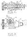
- Figure 2 is a section view taken through the center of the shaft.
- Figure 3 is a partial sectioned view of the engine barring device showing the device engaged with the flywheel and held in a first position.
- Referring to the drawings, and more specifically to Figure 1, a
device 10 for rotating acrankshaft 12 of anengine 14 is shown attached to anengine 14 with fasteners 16. - The
engine 14 includes a flywheel 18 which has a plurality ofexternal teeth 20 thereon and is connected to thecrankshaft 12 in a conventional manner. Astarting system 21 includes astarter motor 22 which could be of either air, hydraulic or electric configuration, a power source 24 such as a compressor, hydraulic pump or battery are included with theengine 14, and a conduit means 26 between the source 24 and thedevice 10 and thedevice 10 and thestarter motor 22. - Referring to Figure 2 and Figure 3, the
device 10 comprises ahousing 28 having athrough bore 30 therein and ashaft 32 extends through thebore 30. Theshaft 32 has opposite ends and agear 34 having a plurality ofexternal teeth 36 is attached to one end of theshaft 32 in a conventional manner. Theshaft 32 is adapted for both axial and rotational movement within thebore 30 and is movable in afirst direction 38 to afirst position 40 so that theteeth 36 on thegear 34 will be drivingly connected with theteeth 20 on the flywheel 18 when thedevice 10 is installed on anengine 14. Ameans 42 for holding theshaft 32 at thefirst position 40 while leaving theshaft 32 free for rotational movement is best disclosed in Figure 3. - The
means 42 for holding includes an annular groove 44 in theshaft 32 located between the ends of theshaft 32, and abore 46 located in thehousing 28 intersecting the throughbore 30. Also included is arod 48 slidably located within thebore 46 and adapted to engage with the groove 44 when theshaft 32 is moved in thefirst direction 38 to thefirst position 40. Further included in theholding means 42 is aspring 49 adapted to automatically engage therod 48 with the annular groove 44 when theshaft 32 is in thefirst position 40. Also included is acounterbore 50 coaxial with the intersectingbore 46 and having a threadedportion 52 and a bottom 54 and a threaded insert 56 engaged with the threadedportion 52 of thecounterbore 50. A throughpassage 58 is located in the threaded insert 56. Therod 48 has opposite ends and an enlarged portion 60 intermediate the ends disposed between the bottom 54 of thecounterbore 50 and the insert 56. Ahandle 62 is connected to therod 48 at one end. Thespring 49 surrounds therod 48 and is located between the enlarged portion 60 and the insert 56 urging therod 48 into the annular groove 44 when theshaft 32 is in thefirst position 38. - The
shaft 32 includes a tool engaging portion, 66 adapted to receive aturning tool 68 as shown in Figure 3. Theengaging portion 66 includes asquare notch 70 located in the end of theshaft 32 opposite thegear 34 end. Thenotch 70 could be of any conventional configuration such as a hex or another shape. - A
means 72 for locking theshaft 32 at one of a plurality of rotational positions 74 is also shown in Figure 2. Themeans 72 for locking includes acounterbore 76 in thehousing 28 coaxial with the throughbore 30, ashoulder 78 at one end of thecounterbore 76 and a threaded portion 80 at the other end of thecounterbore 76. Also included is anannular locking mechanism 82 nonrotatably fixed to and axially slidably supported on theshaft 32, along with anut 84 which has a frictional surface 86 at one end and an externally threadedportion 88. Thenut 84 is slidably fitted over theshaft 32 and adapted to threadably engage the threaded portion 80 of thecounterbore 76 in thehousing 28 so that when thenut 84 is rotated in a direction to move thenut 84 toward theshoulder 78 on thehousing 28, theannular locking mechanism 82 is clamped between the locking mechanism engaging surface 86 and theshoulder 78 preventing theshaft 32 from rotating. As further shown in Figure 2, themeans 72 for locking includes an external spline 90 on theshaft 32 located at the end opposite thegear 34 end along with an internal spline 92 in thelocking mechanism 82 adapted to engage with the external spline 90 on theshaft 32 allowing theshaft 32 to be movable in thefirst direction 38 to thefirst position 40. - The
device 10 further includes anabutting surface 94 located on theshaft 32 at the end opposite thegear 34 end and aspring 96 surrounding theshaft 32 and located between thenut 84 and theabutting surface 94. Thespring 96 urges theshaft 32 in asecond direction 98 to a second position 100 wherein thegear 34 on theshaft 32 is disengaged from theteeth 20 on the flywheel 18. - With the
engine 14 having astarting system 21 as discussed above, thedevice 10 would further include a means 101 for disabling thestarting system 21. The means 101 for disabling includes ameans 102 for blocking theconduit 26 between the source of pressurized fluid 24 and thefluid starting motor 22. Themeans 102 for blocking includes a pair ofports 104 in thehousing 28 connected to the throughbore 30 and a pair ofseals 106 located on theshaft 32 on each side of the annular groove 44. One of the pair ofseals 106 prevents the fluid from passing from the power source 24 of pressurized fluid to thefluid starter motor 22 when theshaft 32 is in thefirst position 40. Themeans 102 for blocking the pressurized fluid also include means 108 for venting the fluid to the atmosphere. Themeans 108 for venting includes a clearance space 110 between thehousing 28 and theshaft 32 and the clearance between the internal splines 92 in thelocking mechanism 82 and the external spline 90 on theshaft 32. The clearance space in this specific embodiment is provided by the spline grooves in theshaft 32. - The
device 10 for rotating thecrankshaft 12 of anengine 14 or a like component such as a compressor is connected to theengine 14. The application of thedevice 10 as discussed below will feature aair starter 22 in conjunction with thedevice 10. During normal operation of theengine 14 andstarter 22, air from a power source 24 flows through theline 26 to thedevice 10, through one of the pair ofports 104, around the groove 44 in theshaft 32 and out the other of the pair ofports 104 throughline 26 to rotate thestarter 22 thus rotating thecrankshaft 12 of theengine 14. - However, during maintenance of the
engine 14, thebarring device 10 is adapted to disable the starting system to prevent rotation of thestarter 22 and enable rotation of thecrankshaft 12 with theturning tool 68. For example, if during the maintenance of theengine 14 thecrankshaft 12 needs to be rotated a very small angle theengine barring device 10 can be used. To activate thebarring device 10, the mechanic exerts a small axial force on the end of theshaft 32 to overcome the force of thespring 96 moving theshaft 32 in thefirst direction 38 to afirst position 40. Theholding means 42 holds theshaft 32 in thefirst position 40 because as theshaft 32 is moved in thefirst direction 38 and the annular groove 44 is aligned with the end of therod 48, the spring 64 biases therod 48 inwardly causing the end of therod 48 to enter into the groove 44. Theshaft 32 is held in thefirst position 40 with theteeth 36 on thegear 34 meshed with theteeth 20 on the flywheel 18. Aturning tool 68, such as a wrench, ratchet or impact wrench, can be inserted into thetool engaging portion 66 in theshaft 32. Using thetool 68, the mechanic rotates theshaft 32 until thecrankshaft 12 of theengine 14 is located in a precisely desired position. The mechanic locks thecrankshaft 12 in this one desired position by tightening thenut 84 into the threaded portion 80 of thecounterbore 76 to clamp theannular locking mechanism 82 between theshoulder 78 and the frictional surface 86 on the nut. The internal splines 92 on thelocking mechanism 82 which are meshed with the external splines 90 on theshaft 32 prevents theshaft 32,gear 34, flywheel 18 andcrankshaft 12 from rotating. Thus, thecrankshaft 12 is held in the precisely desired position and is prevented from rotating. - If the starting
system 21 is activated with the barringdevice 10 engaged, as described above, the flow to theair starter 22 is interrupted preventing thestarter 22 from rotating thecrankshaft 12. As theshaft 32 is moved in thefirst direction 38, the pair ofseals 106 and the groove 44 move relative to thehousing 28. The pair ofseals 106 and the groove 44 move beyond the pair ofports 104, thus allowing air to escape to atmosphere through the clearance space 110 between thehousing 28 and theshaft 32. - After maintenance has been completed, the barring
device 10 is returned to the second position 100 by release of the holding means 42. Thehandle 62 on therod 48 is moved to extract the end of therod 48 from the groove 44. Thespring 96 will urge theshaft 32 in the secondaxial direction 98 into the second position 100 wherein thegear 34 on theshaft 32 is disengaged from theteeth 20 on the flywheel 18. - The
engine barring device 10 discussed above provides for an economical andpositive positioning device 10. The barringdevice 10 interrupts the starting mode of the engine when in thefirst position 40 preventing thestarter 22 from rotating thecrankshaft 12. Thedevice 10 is automatically held in thefirst position 40 enabling the mechanic to rotate thecrankshaft 12 without having to manually hold thedevice 10 in engagement with flywheel 18. The device is also adapted to lock thecrankshaft 12 in a precisely desired position preventing thecrankshaft 12 from rotating.
Claims (11)
Applications Claiming Priority (2)
| Application Number | Priority Date | Filing Date | Title |
|---|---|---|---|
| US06/686,103 US4580534A (en) | 1984-12-24 | 1984-12-24 | Engine barring device |
| US686103 | 1991-04-16 |
Publications (2)
| Publication Number | Publication Date |
|---|---|
| EP0207078A1 EP0207078A1 (en) | 1987-01-07 |
| EP0207078B1 true EP0207078B1 (en) | 1988-12-07 |
Family
ID=24754920
Family Applications (1)
| Application Number | Title | Priority Date | Filing Date |
|---|---|---|---|
| EP85901190A Expired EP0207078B1 (en) | 1984-12-24 | 1985-02-07 | Device for rotating a toothed wheel |
Country Status (7)
| Country | Link |
|---|---|
| US (1) | US4580534A (en) |
| EP (1) | EP0207078B1 (en) |
| JP (1) | JPS62501224A (en) |
| CA (1) | CA1254463A (en) |
| DE (1) | DE3566704D1 (en) |
| IT (2) | IT1184005B (en) |
| WO (1) | WO1986003801A1 (en) |
Families Citing this family (25)
| Publication number | Priority date | Publication date | Assignee | Title |
|---|---|---|---|---|
| US4930371A (en) * | 1988-12-01 | 1990-06-05 | Schneider William J | Apparatus for locking a flywheel |
| US5460138A (en) * | 1994-02-28 | 1995-10-24 | Caterpillar Inc. | Engine barring system |
| US5882181A (en) * | 1996-10-01 | 1999-03-16 | Cummins Engine Company, Inc. | Barring adaptor for an engine air compressor |
| DE10033684B4 (en) * | 2000-07-11 | 2004-04-08 | Loos, Jürgen | turning gear |
| US6644264B2 (en) * | 2001-10-22 | 2003-11-11 | Kohler Co. | Vertical shaft internal combustion engine with overhead power take-off |
| DE10208069C1 (en) * | 2002-02-25 | 2003-12-04 | Loos Juergen | Setting drive for engine rotation system has drive element removable from setting drive housing for reducing overall weight |
| GB0214862D0 (en) * | 2002-06-27 | 2002-08-07 | Cnh Uk Ltd | Engine timing |
| US7007659B2 (en) * | 2004-02-06 | 2006-03-07 | Kohler Co. | Mechanism for removably coupling a shaft of a utilitarian device to an internal combustion engine |
| JP4648774B2 (en) * | 2005-06-23 | 2011-03-09 | 本田技研工業株式会社 | Engine with generator and method of assembling engine with generator |
| FR2897400B1 (en) * | 2006-02-10 | 2009-06-05 | Renault Sas | PIECE FOR LOCKING A FLYWHEEL |
| US7876061B2 (en) * | 2007-06-01 | 2011-01-25 | Progress Rail Services Corp. | Power system with multiple generator units |
| US7952306B2 (en) * | 2007-06-01 | 2011-05-31 | Progress Rail Services Corp | Power system with multiple generator units |
| US7677139B2 (en) * | 2007-08-30 | 2010-03-16 | Jonco Industries, Inc. | Engine turning device |
| US8166753B2 (en) * | 2008-11-24 | 2012-05-01 | Robert Bosch Gmbh | Accumulator system and method of monitoring same |
| US8302720B2 (en) | 2009-01-28 | 2012-11-06 | Robert Bosch Gmbh | Energy storage system for a hybrid vehicle |
| US8186155B2 (en) * | 2009-01-30 | 2012-05-29 | Robert Bosch Gmbh | Hydraulic energy storage system with accumulator and method of varying charge of same |
| US7913791B2 (en) | 2009-05-04 | 2011-03-29 | Robert Bosch Gmbh | Energy storage system for a hybrid vehicle |
| US8631726B2 (en) | 2011-04-05 | 2014-01-21 | International Truck Intellectual Property Company, Llc | Torque limiting engine rotation tool |
| CN102410104A (en) * | 2011-12-10 | 2012-04-11 | 常州常瑞天力动力机械有限公司 | Diesel engine locating device |
| CN106014747B (en) * | 2016-07-07 | 2017-05-10 | 重庆双奥机械制造有限公司 | Electric motor starter with function of manual turning |
| US11260516B1 (en) | 2020-02-18 | 2022-03-01 | Ryan Roberts | Barring device attachment for providing engine maintenance |
| CN111561443B (en) * | 2020-04-23 | 2022-06-10 | 宝鸡石油机械有限责任公司 | Fracturing pump electric disc pump device |
| CN113931739B (en) * | 2021-09-29 | 2022-11-29 | 中国航发动力股份有限公司 | Positioning device of high-pressure fuel oil parking switch and replacing method thereof |
| US12313064B2 (en) * | 2022-08-15 | 2025-05-27 | EKU Power Drives GmbH | Reciprocating pump turning and barring tool |
| US12509998B1 (en) | 2024-08-21 | 2025-12-30 | Hamilton Sundstrand Corporation | Crank gear |
Family Cites Families (13)
| Publication number | Priority date | Publication date | Assignee | Title |
|---|---|---|---|---|
| US1887998A (en) * | 1929-10-21 | 1932-11-15 | Twin Coach Co | Internal combustion engine |
| US2288228A (en) * | 1941-02-08 | 1942-06-30 | Biasse Tony De | Device for repairing automative engines |
| US2694901A (en) * | 1949-05-20 | 1954-11-23 | Crane Co | Valve operating mechanism |
| US2879673A (en) * | 1953-04-03 | 1959-03-31 | Collins Radio Co | Disengageable shaft locking mechanism |
| US2724289A (en) * | 1954-04-27 | 1955-11-22 | Janette Electric Mfg Co | Coupling apparatus |
| GB810815A (en) * | 1956-06-06 | 1959-03-25 | Danly Mach Specialties Inc | Inching assembly for power presses |
| US3321985A (en) * | 1964-11-09 | 1967-05-30 | Roland T Wheeler | Engine turn-over attachment |
| US3395588A (en) * | 1967-06-29 | 1968-08-06 | Caterpillar Tractor Co | Flywheel rotation device |
| DE1914332A1 (en) * | 1968-08-02 | 1970-04-16 | Haslemere Cinema Company Ltd | Combined adjustment tool |
| US4072063A (en) * | 1977-02-14 | 1978-02-07 | Caterpillar Tractor Co. | Engine cranking adapter |
| FR2445754A1 (en) * | 1979-01-08 | 1980-08-01 | Harmand Pierre | TILTABLE SUPPORT FOR OBJECT OR WORKPIECE |
| JPS56101063A (en) * | 1980-01-11 | 1981-08-13 | Toyota Motor Corp | Starting device in internal combustion engine testing device |
| DE3312316C2 (en) * | 1983-04-06 | 1985-05-23 | Klöckner-Humboldt-Deutz AG, 5000 Köln | Device for cranking a reciprocating internal combustion engine by hand |
-
1984
- 1984-12-24 US US06/686,103 patent/US4580534A/en not_active Expired - Fee Related
-
1985
- 1985-02-07 JP JP60500782A patent/JPS62501224A/en active Pending
- 1985-02-07 WO PCT/US1985/000185 patent/WO1986003801A1/en not_active Ceased
- 1985-02-07 EP EP85901190A patent/EP0207078B1/en not_active Expired
- 1985-02-07 DE DE8585901190T patent/DE3566704D1/en not_active Expired
- 1985-10-31 CA CA000494377A patent/CA1254463A/en not_active Expired
- 1985-12-09 IT IT68029/85A patent/IT1184005B/en active
- 1985-12-09 IT IT8554188U patent/IT8554188V0/en unknown
Also Published As
| Publication number | Publication date |
|---|---|
| IT1184005B (en) | 1987-10-22 |
| DE3566704D1 (en) | 1989-01-12 |
| IT8568029A1 (en) | 1987-06-09 |
| IT8568029A0 (en) | 1985-12-09 |
| CA1254463A (en) | 1989-05-23 |
| US4580534A (en) | 1986-04-08 |
| IT8554188V0 (en) | 1985-12-09 |
| WO1986003801A1 (en) | 1986-07-03 |
| EP0207078A1 (en) | 1987-01-07 |
| JPS62501224A (en) | 1987-05-14 |
Similar Documents
| Publication | Publication Date | Title |
|---|---|---|
| US4580534A (en) | Engine barring device | |
| US5083619A (en) | Powered impact wrench | |
| US4429591A (en) | Drive shifting apparatus for valve control and the like | |
| EP0193097B1 (en) | Removable key and methods for its use | |
| US3631688A (en) | Shaft coupling locking device and tool for installation thereof | |
| EP0202130A1 (en) | Ratchet wrench | |
| US8439763B2 (en) | Wedge clutch assembly | |
| US20090038904A1 (en) | Wedge clutch assembly | |
| US5460138A (en) | Engine barring system | |
| JPS6119395B2 (en) | ||
| US4289049A (en) | Bolt holding machine wrench | |
| US3120221A (en) | Pneumatic valve return for internal combustion engines | |
| US7874222B2 (en) | Two-speed PTO stub shaft exchange improvements | |
| US5438891A (en) | Collet type fastener removal tool | |
| US3220526A (en) | One shot clutch | |
| EP3829818B1 (en) | Ratcheting tool | |
| US3199644A (en) | Automatic releasing clutch mechanism responsive to torque loads for use in power tools | |
| US20060124425A1 (en) | Planar coupling assembly | |
| US20060135267A1 (en) | Wedge clutch assembly | |
| US4901832A (en) | Freewheel drive for the starter of an internal combustion engine | |
| US2786379A (en) | Hydraulically controlled, gear operated wrench | |
| US3401445A (en) | Grappling device | |
| EP2632634A1 (en) | Chucking device for a hand machine tool | |
| US4805470A (en) | Starter jaw blocker | |
| US5906147A (en) | Wrench-to-bolt coupling assembly |
Legal Events
| Date | Code | Title | Description |
|---|---|---|---|
| PUAI | Public reference made under article 153(3) epc to a published international application that has entered the european phase |
Free format text: ORIGINAL CODE: 0009012 |
|
| 17P | Request for examination filed |
Effective date: 19860819 |
|
| AK | Designated contracting states |
Kind code of ref document: A1 Designated state(s): CH DE FR GB LI NL SE |
|
| 17Q | First examination report despatched |
Effective date: 19870709 |
|
| GRAA | (expected) grant |
Free format text: ORIGINAL CODE: 0009210 |
|
| AK | Designated contracting states |
Kind code of ref document: B1 Designated state(s): CH DE FR GB LI NL SE |
|
| REF | Corresponds to: |
Ref document number: 3566704 Country of ref document: DE Date of ref document: 19890112 |
|
| ET | Fr: translation filed | ||
| PLBE | No opposition filed within time limit |
Free format text: ORIGINAL CODE: 0009261 |
|
| STAA | Information on the status of an ep patent application or granted ep patent |
Free format text: STATUS: NO OPPOSITION FILED WITHIN TIME LIMIT |
|
| 26N | No opposition filed | ||
| PGFP | Annual fee paid to national office [announced via postgrant information from national office to epo] |
Ref country code: FR Payment date: 19930108 Year of fee payment: 9 |
|
| PGFP | Annual fee paid to national office [announced via postgrant information from national office to epo] |
Ref country code: SE Payment date: 19930120 Year of fee payment: 9 |
|
| PG25 | Lapsed in a contracting state [announced via postgrant information from national office to epo] |
Ref country code: SE Effective date: 19940208 |
|
| PG25 | Lapsed in a contracting state [announced via postgrant information from national office to epo] |
Ref country code: FR Effective date: 19941031 |
|
| PGFP | Annual fee paid to national office [announced via postgrant information from national office to epo] |
Ref country code: GB Payment date: 19941230 Year of fee payment: 11 |
|
| REG | Reference to a national code |
Ref country code: FR Ref legal event code: ST |
|
| PGFP | Annual fee paid to national office [announced via postgrant information from national office to epo] |
Ref country code: DE Payment date: 19950117 Year of fee payment: 11 |
|
| EUG | Se: european patent has lapsed |
Ref document number: 85901190.0 Effective date: 19940910 |
|
| PGFP | Annual fee paid to national office [announced via postgrant information from national office to epo] |
Ref country code: NL Payment date: 19950228 Year of fee payment: 11 |
|
| PGFP | Annual fee paid to national office [announced via postgrant information from national office to epo] |
Ref country code: CH Payment date: 19950404 Year of fee payment: 11 |
|
| PG25 | Lapsed in a contracting state [announced via postgrant information from national office to epo] |
Ref country code: GB Effective date: 19960207 |
|
| PG25 | Lapsed in a contracting state [announced via postgrant information from national office to epo] |
Ref country code: LI Free format text: LAPSE BECAUSE OF NON-PAYMENT OF DUE FEES Effective date: 19960228 Ref country code: CH Free format text: LAPSE BECAUSE OF NON-PAYMENT OF DUE FEES Effective date: 19960228 |
|
| PG25 | Lapsed in a contracting state [announced via postgrant information from national office to epo] |
Ref country code: NL Effective date: 19960901 |
|
| GBPC | Gb: european patent ceased through non-payment of renewal fee |
Effective date: 19960207 |
|
| REG | Reference to a national code |
Ref country code: CH Ref legal event code: PL |
|
| NLV4 | Nl: lapsed or anulled due to non-payment of the annual fee |
Effective date: 19960901 |
|
| PG25 | Lapsed in a contracting state [announced via postgrant information from national office to epo] |
Ref country code: DE Effective date: 19961101 |