EP0207066A2 - Method and apparatus for manufacturing ingots - Google Patents
Method and apparatus for manufacturing ingots Download PDFInfo
- Publication number
- EP0207066A2 EP0207066A2 EP86890177A EP86890177A EP0207066A2 EP 0207066 A2 EP0207066 A2 EP 0207066A2 EP 86890177 A EP86890177 A EP 86890177A EP 86890177 A EP86890177 A EP 86890177A EP 0207066 A2 EP0207066 A2 EP 0207066A2
- Authority
- EP
- European Patent Office
- Prior art keywords
- mold
- cooled
- electrode
- heat
- attachment
- Prior art date
- Legal status (The legal status is an assumption and is not a legal conclusion. Google has not performed a legal analysis and makes no representation as to the accuracy of the status listed.)
- Granted
Links
Images
Classifications
-
- B—PERFORMING OPERATIONS; TRANSPORTING
- B22—CASTING; POWDER METALLURGY
- B22D—CASTING OF METALS; CASTING OF OTHER SUBSTANCES BY THE SAME PROCESSES OR DEVICES
- B22D27/00—Treating the metal in the mould while it is molten or ductile ; Pressure or vacuum casting
- B22D27/04—Influencing the temperature of the metal, e.g. by heating or cooling the mould
- B22D27/06—Heating the top discard of ingots
-
- B—PERFORMING OPERATIONS; TRANSPORTING
- B22—CASTING; POWDER METALLURGY
- B22D—CASTING OF METALS; CASTING OF OTHER SUBSTANCES BY THE SAME PROCESSES OR DEVICES
- B22D7/00—Casting ingots, e.g. from ferrous metals
- B22D7/06—Ingot moulds or their manufacture
- B22D7/10—Hot tops therefor
Definitions
- the invention relates to a method and an apparatus for the production of blocks, in which a metallic melt, e.g. Steel melt is introduced into a one-part or multi-part mold with an attachment, whereupon the block is allowed to solidify with the addition of heat.
- a metallic melt e.g. Steel melt
- Typical defects are the negatively segregated bottom cone, in many cases also contaminated with non-metallic inclusions, shrinkage cavities, connected with V segregations in the block axis, in the block crest the positive segregation with enrichments of C, S and P, and finally the A or h segregations with enrichments of S and P. There is currently no generally accepted theory for the origin of these segregations.
- a water-cooled ring is inserted into a conventional forging block mold, the mold is filled with steel, and a layer of metallurgically active slag is placed on the steel, into which an electrode is immersed.
- the slag bath is heated so strongly that the electrode melts and compensates for shrinkage cavities in the block during the solidification process.
- the solidification can also be influenced by targeted variation of the energy supply. Blocks produced by this method have no negative soil segregation with the associated disadvantages, no V segregation and hardly any shrinkage cavities. This has been demonstrated on several thousand forging blocks that were manufactured using this method.
- the object of the present invention is now to create a method and a device which also make it possible to reliably avoid substitute error sizes by 1 mm, at the same time requiring no increased or no significantly increased effort both on the energy side and for the devices should be.
- a metallic melt e.g. Melting steel
- an attachment in particular a water-cooled hood, preferably to below the attachment
- an electrically conductive slag preferably liquefied hot slag
- the melt heat and optionally further melt is fed consists essentially in that the mold in its upper region and thus the solidifying block below the cap retards heat, in particular solidification heat, and / or is dissipated, preferably the lower part of the mold, in particular the base plate, is cooled, preferably fluid-cooled, while heat and, if appropriate, molten metal is supplied via the electrode during the solidifying block.
- heat is supplied to the slag with a power density of 0.4 to 2.0, in particular 0.5 to 2.0 kW / cm 2 and a current density of 8 to 25 A / cm 2 in each case Electrode. It can be achieved that two superimposed forces occur in the slag, the thermally induced force causing a bath movement in such a way that the slag rises below the electrode, moves on the surface to the outside of the hood and then the cooled slag to the Surface of the molten metal comes and cools down.
- the advantageous slag movement which is caused by the preferably larger Lorenz force, runs approximately in the opposite direction into the block, namely the hot slag sinks below the electrode to the metal surface, releases its heat to the metal mirror and then moves to the edge of the attachment , rises up there along the wall and the cooled slag moves back to the electrode on the surface of the slag level.
- This also creates a lid made of solidified slag, which is also desirable because thermal insulation is achieved.
- the inventive device for producing metallic blocks having a Kokillearranged multi-part mold which comprises an optionally liquid cooled articles, in which a particular severzehrenoe electrode projects, which is p with a pole of an S coupled annungsouelle, while a further electrode and / or the bottom area , especially the Bottom plate of the mold is connected to another pole of the voltage source, consists essentially in that the mold is thermally insulating in its upper region below the attachment, in particular has thermal insulation, preferably on the outer wall of the mold, which is preferably over a third the height of the mold extends without an attachment and that preferably the base plate can be cooled, in particular fluid-cooled.
- the mold has a greater wall thickness towards its lower region, in particular one assigned to the base plate, than towards its upper region.
- the higher wall thickness in the lower area results in a higher heat absorption capacity due to the higher mass, in addition the contact area with the base plate is increased, while the lower wall thickness in the upper area results in a reduced heat absorption capacity.
- the device for producing blocks shown schematically in the drawing has a base plate 1, which is supplied with cooling water via water supply and discharge lines 2, 3, cooling with another fluid, e.g. Liquid metal, gases or the like can also be made.
- a base plate 1 which is supplied with cooling water via water supply and discharge lines 2, 3, cooling with another fluid, e.g. Liquid metal, gases or the like can also be made.
- On the base plate there is a lower part 4 of the mold, which has a recess 5 into which the pouring channel opens for an increasing casting.
- the middle part 6 of the mold has a slightly conical cross section that opens upwards.
- an upper mold part 7 is placed, which carries on its outside thermal insulation 8, which is filled with mineral insulation, for example mineral wool, vermiculite or asbestos, and has a sheet metal jacket for protection against mechanical damage.
- a water-cooled attachment 9 is provided, in which a melting electrode 10 is arranged. Both the base plate 1 and the electrode 10 are connected to a voltage source 11, shown schematically.
- the melt was then across the electrode in the course of solidification of 1 0 hours heat and indeed initially with a procedurecichte of 1.33 kW / cm 2 and a current density of 12 amperes / cm 2 at the electrode.
- the block solidified completely after 16 hours, whereupon both the coolant supply to the base plate and to the attachment was interrupted, and at the same time no further heat was supplied via the melting electrode.
- the block thus obtained was examined with ultrasound and showed no inclusions with substitute defect sizes of around 1 mm in the foot, in the center or in the head.
- Example 2 The procedure was analogous to Example 1, but the device had no thermal insulation in the upper third of the mold.
- the block did not have a negatively inclined bottom cone with partially coarse non-metallic inclusions, had hardly any lambda or shadow stripes, and there were no V-segregations and hardly any shrinkage cavities, but non-metallic inclusions with substitute error sizes of around 1 mm were found during the ultrasound test.
Abstract
Description
Die Erfindung bezieht sich auf ein Verfahren und auf eine Vorrichtung zur Herstellung von Blöcken, wobei eine metallische Schmelze, z.B. Stahlschmelze in eine ein- oder mehrteilige Kokille mit Aufsatz eingebracht wird, worauf unter Wärmezufuhr der Block erstarren gelassen wird.The invention relates to a method and an apparatus for the production of blocks, in which a metallic melt, e.g. Steel melt is introduced into a one-part or multi-part mold with an attachment, whereupon the block is allowed to solidify with the addition of heat.
Die Erzeugung schwerer Schmiedeblöcke als Ausgangsprodukt für Schmiedestücke für den Kraftwerksbau stellt eine der größten Herausforderungen für den Stahlwerker dar. Die Anforderungen der Turbinenbauer an Reinheitsgrad und Freiheit von Seigerungen sind auch mit modernen Verfahren nur schwer einzuhalten.The production of heavy forgings as the starting product for forgings for power plant construction represents one of the greatest challenges for the steelworker. The requirements of the turbine builders regarding the degree of purity and freedom from segregation are difficult to meet even with modern processes.
Während Erschmelzung und Schmelzbehandlung in den letzten Jahren durch den Einsatz moderner Pfannenmetallurgieanlagen große Fortschritte erzielt haben, bleibt die Erstarrung im konventionellen Blockguß nach wie vor das am wenigsten zu beeinflussende Glied in der Erzeugungskette.While melting and melting treatment have made great progress in recent years through the use of modern ladle metallurgy systems, solidification in conventional ingot casting remains the least influenced link in the production chain.
Typische Fehlerscheinungen sind der negativ geseigerte Bodenkegel, in vielen Fällen auch mit nichtmetallischen Einschlüssen verunreinigt, Schrumpfungshohlräume, verbunden mit V-Seigerungen in der Blockachse, im Blockschopf die positive Seigerung mit Anreicherungen von C, S und P, schließlich die A- oder h-Seigerungen mit Anreicherungen von S und P. Für die Entstehung dieser Seigerungen gibt es zurzeit noch keine allgemein anerkannte Theorie.Typical defects are the negatively segregated bottom cone, in many cases also contaminated with non-metallic inclusions, shrinkage cavities, connected with V segregations in the block axis, in the block crest the positive segregation with enrichments of C, S and P, and finally the A or h segregations with enrichments of S and P. There is currently no generally accepted theory for the origin of these segregations.
Um nichtmetallische Einschlüsse aus dem Bodenkegel zu vermeiden, müssen bei schweren Blöcken 15 9G:und mehr vom Blockboden abgesetzt werden. Der Anteil des verloreren Kopfes kann bei sehr schweren Blöcken 25 und mehr Prozente betragen. Eine Beeinflussung der Erstarrung ist nur in sehr beschränktem Ausmaß über Änderungen der Blockgeometrie oder des isolierenden Haubeneinsatzes möglich.In order to avoid non-metallic inclusions from the floor cone, 15 9G: and more must be removed from the floor of the block in the case of heavy blocks. The proportion of the lost head can be 25 and more percent in very heavy blocks. It is only possible to influence the solidification to a very limited extent by changing the block geometry or the insulating hood insert.
Diese Fehler können mit dem folgenden Verfahren vermieden werden. In eine herkömmliche Schmiedeblockkokille wird ein wassergekühlter Ring eingesetzt, die Kokille mit Stahl gefüllt, auf den Stahl kommt eine Schichte metallurgisch aktiver Schlacke, in die eine Elektrode eingetaucht wird. Durch Zufuhr elektrischer Energie wird das Schlackenbad so stark erhitzt, daß die Elektrode abschmilzt und während des Erstarrungsprozesses Schrumpfungshohlräume im Block ausgleicht. Durch gezielte Variation der Energiezufuhr kann auch die Erstarrung beeinflußt werden. Blöcke, die nach diesem Verfahren hergestellt werden, weisen keine negative Bodenseigerung mit den damit verbundenen Nachteilen, keine V-Seigerungen und kaum Schrumpfungshohlräume auf. Dies konnte an mehreren tausend Schmiedeblöcken, die nach diesem Verfahren hergestellt wurden, bewiesen werden.These errors can be avoided using the following procedure. A water-cooled ring is inserted into a conventional forging block mold, the mold is filled with steel, and a layer of metallurgically active slag is placed on the steel, into which an electrode is immersed. By supplying electrical energy, the slag bath is heated so strongly that the electrode melts and compensates for shrinkage cavities in the block during the solidification process. The solidification can also be influenced by targeted variation of the energy supply. Blocks produced by this method have no negative soil segregation with the associated disadvantages, no V segregation and hardly any shrinkage cavities. This has been demonstrated on several thousand forging blocks that were manufactured using this method.
Von Turbinenherstellern wird nunmehr auch sehr fein verteilten nichtmetallischen Einschlüssen mit Ersatzfehlergrößen um 1 mm bei der Ultraschallprüfung besondere Bedeutung beigemessen. Derartige Fehler konnten mit dem oben angeführten Verfahren nicht mit ausreichender Sicherheit vermieden werden.Turbine manufacturers are now attaching particular importance to very finely divided non-metallic inclusions with substitute defect sizes of around 1 mm in ultrasonic testing. Such errors could not be avoided with sufficient certainty using the above method.
Die Aufgabe der vorliegenden Erfindung besteht nun darin, ein Verfahren und eine Vorrichtung zu schaffen, die es erlauben,auch mit Sicherheit Ersatzfehlergrößen um 1 mm zu vermeiden, wobei gleichzeitig kein erhöhter oder kein wesentlich erhöhter Aufwand sowohl von der Energieseite als auch für die Vorrichtungen erforderlich sein soll.The object of the present invention is now to create a method and a device which also make it possible to reliably avoid substitute error sizes by 1 mm, at the same time requiring no increased or no significantly increased effort both on the energy side and for the devices should be.
Das erfindungsgemäße Verfahren zur Herstellung von Blöcken, wobei eine metallische Schmelze, z.B. Stahlschmelze, in eine ein- oder mehrteilige Kokille mit Aufsatz, insbesondere wassergekühlter Haube, vorzugsweise bis unterhalb des Aufsatzes eingebracht wird, worauf eine elektrisch leitende Schlacke,bevorzugt verflüssigte heiße Schlacke auf den Metallspiegel aufgebracht und über eine, insbesondere selbstverzehrende Elektrode aus einer gegebenenfalls der metallischen Schmelze im wesentlichen entsprechenden Zusammensetzung, der Schmelze Wärme und gegebenenfalls weitere Schmelze zugeführt wird, besteht im wesentlichen darin, daß der Kokille in ihrem oberen Bereich und damit dem erstarrenden Block unterhalb des Aufsatzes verzögert Wärme, insbesondere Erstarrungswärme abgeführt und/oder abgeleitet wird, wobei vorzugsweise der untere Teil der Kokille insbesondere die Bodenplatte gekühlt, vorzugsweise fluidgekühlt wird, während dem erstarrenden Block Wärme und gegebenenfalls Metallschmelze über die Elektrode zugeführt'wir.d.The process according to the invention for the production of blocks, wherein a metallic melt, e.g. Melting steel, is introduced into a one-part or multi-part mold with an attachment, in particular a water-cooled hood, preferably to below the attachment, whereupon an electrically conductive slag, preferably liquefied hot slag, is applied to the metal mirror and via a, in particular self-consuming, electrode from a metal, if appropriate Melt essentially corresponding composition, the melt heat and optionally further melt is fed consists essentially in that the mold in its upper region and thus the solidifying block below the cap retards heat, in particular solidification heat, and / or is dissipated, preferably the lower part of the mold, in particular the base plate, is cooled, preferably fluid-cooled, while heat and, if appropriate, molten metal is supplied via the electrode during the solidifying block.
Durch diese gezielte Wärmezufuhr und Wärmeableitung bzw. Kühlung kann erreicht werden, daß der Block schalenweise erstarrt, wobei im Blockkopf die Erstarrung so lange verhindert werden kann, daß keine flaschenhalsartigen Verengungen der bereits erstarrten Schmelze eintreten, wodurch Seigerungen oder Einschlüsse und dgl., welche den oben angeführten Fehler verursachen, vermeidbar sind. Es war nun durchaus überraschend, daß mit einer derartigen gezielten Erstarrung es auch erreicht werden kann, daß diese Fehler, welche teilweise auf nichtmetallische Einschlüsse zurückzuführen sind, durch vermutlicherweise Aufsteigen oder Aufschwimmen diese nichtmetallischen Einschlüsse beseitigt werden können.This targeted supply of heat and heat dissipation or cooling can cause the block to solidify in shells, whereby the solidification in the block head can be prevented so long that no bottle-neck-like constrictions of the already solidified melt occur, causing segregations or inclusions and the like, which the cause errors mentioned above, are avoidable. It was now quite surprising that with such a targeted solidification it can also be achieved that these errors, which are partly due to non-metallic inclusions, can presumably be eliminated by ascending or floating these non-metallic inclusions.
Gemäß einem weiteren Merkmal der vorliegenden Erfindung wird der Schlacke Wärme zugeführt mit einer Leistungsdichte von 0,4 bis 2,0, insbesondere 0,5 bis 2,0 kW/cm2 und einer Stromdichte von 8 bis 25 A/cm2jeweils an der Elektrode. Damit läßt sich erreichen, daß in der Schlacke zwei sich überlagernde Kräfte auftreten, wobei die thermisch bedingte Kraft eine Badbewegung in der Weise bewirkt, daß die Schlacke unterhalb der Elektrode aufsteigt, an der Oberfläche zur Haubenaußenseite sich bewegt und sodann die nunmehr abgekühlte Schlacke an die Oberfläche der Metallschmelze kommt und damit abkühlt. Die vorteilhafte Schlackenbewegung, welche durch die bevorzugt größere Lorenzkraft bewirkt wird, verläuft etwa gegensinnig in den Block hinein gerichtet, und zwar sinkt die heiße Schlacke unterhalb der Elektrode bis zur Metalloberfläche, gibt ihre Wärme an den Metallspiegel ab und bewegt sich hierauf zum Rand des Aufsatzes, steigt dort entlang der Wand hoch, und die abgekühlte Schlacke bewegt sich an der Oberfläche des Schlackenspiegels wieder zur Elektrode. Dadurch entsteht weiters ein Deckel aus erstarrter Schlacke, welcher ebenfalls erwünscht ist, da eine thermische Isolierung erreicht wird. Mit einer derartigen Schlackenbewegung wird weiters auch ein flaschenartiges Einschnüren des Blockes beim Erstarren vermieden.According to a further feature of the present invention, heat is supplied to the slag with a power density of 0.4 to 2.0, in particular 0.5 to 2.0 kW / cm 2 and a current density of 8 to 25 A / cm 2 in each case Electrode. It can be achieved that two superimposed forces occur in the slag, the thermally induced force causing a bath movement in such a way that the slag rises below the electrode, moves on the surface to the outside of the hood and then the cooled slag to the Surface of the molten metal comes and cools down. The advantageous slag movement, which is caused by the preferably larger Lorenz force, runs approximately in the opposite direction into the block, namely the hot slag sinks below the electrode to the metal surface, releases its heat to the metal mirror and then moves to the edge of the attachment , rises up there along the wall and the cooled slag moves back to the electrode on the surface of the slag level. This also creates a lid made of solidified slag, which is also desirable because thermal insulation is achieved. With such a slag movement, a bottle-like constriction of the block during solidification is also avoided.
Die erfindungsgemäße Vorrichtung zur Herstellung von metallischen Blöcken mit einer Kokilleinsbesondere mehrteiligen Kokille, die einen gegebenenfalls flüssigkeitsgekühlten, Aufsatz aufweist, in welchen eine insbesondere selbstverzehrenoe Elektrode ragt, die mit einem Pol einer Spannungsouelle verbunden ist, während eine weitere Elektrode und/oder der Bodenbereich, insbesondere die Bodenplatte der Kokille mit einem weiteren Pol der Spannungsquelle verbunden ist, besteht im wesentlichen darin, daß die Kokille in ihrem oberen Bereich unterhalb des Aufsatzes thermisch isolierend ist, insbesondere eine thermische Isolierung, vorzugsweise an der Außenwand der Kokille aufweist, die sich bevorzugt über ein Drittel der Höhe der Kokille ohne Aufsatz erstreckt und daß vorzugsweise die Bodenplatte kühlbar, insbesondere fluidkühlbar ist.The inventive device for producing metallic blocks having a Kokilleinsbesondere multi-part mold, which comprises an optionally liquid cooled articles, in which a particular selbstverzehrenoe electrode projects, which is p with a pole of an S coupled annungsouelle, while a further electrode and / or the bottom area , especially the Bottom plate of the mold is connected to another pole of the voltage source, consists essentially in that the mold is thermally insulating in its upper region below the attachment, in particular has thermal insulation, preferably on the outer wall of the mold, which is preferably over a third the height of the mold extends without an attachment and that preferably the base plate can be cooled, in particular fluid-cooled.
Durch die thermische Isolierung der Kokille unterhalb ihres gekühlten Aufsatzes kann nun erreicht werden, daß der Block das erwünschte Erstarrungsverhalten aufweist, wobei durch eine fluidgekühlte Bodenplattedas bevorzugte Erstarren des Blockfußes noch weiter gefördert werden kann. Eine derartige Einrichtung ist besonders einfach und es war auch nicht naheliegend, sie so zu konzipieren, da an einem Block unterschiedliche scheinbar zueinander entgegengesetzte Wirkungen erreicht werden, und zwar Zuführung von Wärme, verzögertes Abkühlen und bevorzugtes Abkühlen.The thermal insulation of the mold below its cooled attachment can now be used to ensure that the block has the desired solidification behavior, and the preferred solidification of the block base can be further promoted by a fluid-cooled base plate. Such a device is particularly simple and it was also not obvious to design it in such a way, since different effects appearing to be opposite to one another are achieved on a block, namely supplying heat, delayed cooling and preferential cooling.
Gemäß einem weiteren Merkmal der vorliegenden Erfindung weist bei einer mehrteiligen Kokille im wesentlichen der gesamte obere Teil derselben eine thermische Isolierung auf.According to a further feature of the present invention, in the case of a multi-part mold, essentially the entire upper part thereof has thermal insulation.
Schließlich ist es gemäß einer weiteren Ausführungsform bevorzugt und verstärkt die Effekte der unterschiedlichen Wärmeabfuhr, wenn die Kokille zu ihrem unteren, insbesondere der Bodenplatte zugeordneten Bereich hin eine höhere Wandstärke aufweist, als zu ihrem oberen Bereich hin. Die höhere Wandstärke im unteren Bereich bewirkt infolge der höheren Masse ein höheres Wärmeaufnahmevermögen, darüber hinaus ist die Kontaktfläche mit der Bodenplatte erhöht, während die geringere Wanddicke im oberen Bereich ein vermindertes Wärmeschluckvermögen bewirkt.Finally, according to a further embodiment, it is preferred and reinforces the effects of the different heat dissipation if the mold has a greater wall thickness towards its lower region, in particular one assigned to the base plate, than towards its upper region. The higher wall thickness in the lower area results in a higher heat absorption capacity due to the higher mass, in addition the contact area with the base plate is increased, while the lower wall thickness in the upper area results in a reduced heat absorption capacity.
Im folqenden wird die Erfindung anhand der Beispiele und der Zeichnung, in welcher eine Kokille mit Blockkopfheizung dargestellt ist, näher erläutert.In the folqenden the invention is explained in more detail using the examples and the drawing, in which a mold with block head heating is shown.
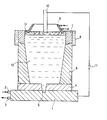
Die in der Zeichnung schematisch dargestellte Vorrichtung zur Herstellung von Blöcken weist eine Bodenplatte 1 auf, die über Wasserzu- und -ableitungen 2, 3 mit Kühlwasser versorgt wird, eine Kühlung mit einem anderen Fluid z.B. Flüssigmetall, Gase od. dgl. kann ebenfalls erfolgen. Auf der Bodenplatte liegt ein unterer Teil 4 der Kokille auf, welcher eine Ausnehmung 5 besitzt, in welche der Gießkanal für einen steigenden Guß mündet. Der mittlere Teil 6 der Kokille weist einen leicht konischen nach oben sich öffnenden Querschnitt auf. Auf diesem Kokillenteil 6 ist ein oberer Kokillenteil 7 aufgesetzt, der an seiner Außenseite eine thermische Isolierung 8 trägt, die mit einer mineralischen Isolierungbeispielsweise Mineralwolle, Vermiculit oder Asbest gefüllt ist, und einen Blechmantel zum Schutz gegen mechanische Beschädigung aufweist. Weiters ist ein wassergekühlter Aufsatz 9 vorgesehen, in welchem eine abschmelzende Elektrode 10 angeordnet ist. Sowohl die Bodenplatte 1 als auch die Elektrode 10 sind mit einer schematisch dargestellten Spannungsquelle 11 verbunden. Wie aus der Zeichnung ersichtlich, reicht die Metallschmelze 12 nicht bis zum Aufsatz 9, sondern es befindet sich zwischen Aufsatz und Metallschmelze eine erschmolzene Schlacke 13.The device for producing blocks shown schematically in the drawing has a base plate 1, which is supplied with cooling water via water supply and
In einer Vorrichtung gemäß der Zeichnung wurden 36 t einer Schmelze folgender chemischer Zusammensetzung in Gew.-% C 0,27, S 0,001, P 0,003, Mn 0,40, Cr 1,32, Mo 0,44, Ni 2,64, V 0,05 und danach eine Elektrode mit einem Durchmesser von 300 mm eingebracht. Auf die Metallschmelze wurde sodann eine flüssige, erschmolzene Schlacke aufgebracht, worauf der Aufsatz in die Schlacke eingetaucht wurde, wobei ein Eintauchen desselben in die Metallschmelze vermieden wurde. Sodann wurde eine Elektrode mit einem Durchmesser von 300 mm in die Schlacke eingetaucht. Der Schmelze wurde sodann über die Elektrode im Laufe des Erstarrens von 10 Stunden Wärme und zwar anfänglich mit einer Leistungscichte von 1,33 kW/cm2 und einer Stromdichte von 12 Ampere/cm2 an der Elektrode zugeführt. Der Block war nach 16 Stunden vollkommen erstarrt, worauf sowohl die Kühlmittelzufuhr zur Bodenplatte als auch zum Aufsatz unterbrochen wurde, und gleichzeitig nicht weitere Wärme über die abschmelzende Elektrode zugeführt wurde. Der so erhaltene Block wurde mit Ultraschall geprüft und wies weder im Fuß noch im Zentrum,noch im Kopf Einschlüsse mit Ersatzfehlergrößen um 1 mm auf.In a device according to the drawing, 36 t of a melt of the following chemical composition in wt .-% C 0.27, S 0.001, P 0.003, Mn 0.40, Cr 1.32, Mo 0.44, Ni 2.64, V 0.05 and then an electrode with a diameter of 300 mm. A liquid, molten slag was then applied to the molten metal, whereupon the attachment was immersed in the slag, avoiding immersion thereof in the molten metal. An electrode with a diameter of 300 mm was then immersed in the slag. The melt was then across the electrode in the course of solidification of 1 0 hours heat and indeed initially with a Leistungscichte of 1.33 kW / cm 2 and a current density of 12 amperes / cm 2 at the electrode. The block solidified completely after 16 hours, whereupon both the coolant supply to the base plate and to the attachment was interrupted, and at the same time no further heat was supplied via the melting electrode. The block thus obtained was examined with ultrasound and showed no inclusions with substitute defect sizes of around 1 mm in the foot, in the center or in the head.
Es wurde analog Beispiel 1 vorgegangen, jedoch hatte die Vorrichtung keine thermische Isolierung im oberen Drittel der Kokille. Der Block wies zwar keinen negativ geseigerten Bodenkegel mit teilweise groben nichtmetallischen Einschlüssen auf, besaß kaum Lambda- oder Schattenstreifen, und es waren.keine V-Seigerungen und kaum Schwindungshohlräume vertreten, jedoch bei der Ultraschallprüfung konnten nichtmetallische Einschlüsse mit Ersatzfehlergrößen um 1 mm festgestellt werden.The procedure was analogous to Example 1, but the device had no thermal insulation in the upper third of the mold. The block did not have a negatively inclined bottom cone with partially coarse non-metallic inclusions, had hardly any lambda or shadow stripes, and there were no V-segregations and hardly any shrinkage cavities, but non-metallic inclusions with substitute error sizes of around 1 mm were found during the ultrasound test.
Claims (5)
Applications Claiming Priority (2)
| Application Number | Priority Date | Filing Date | Title |
|---|---|---|---|
| AT0182885A AT395296B (en) | 1985-06-19 | 1985-06-19 | METHOD AND DEVICE FOR PRODUCING BLOCKS |
| AT1828/85 | 1985-06-19 |
Publications (3)
| Publication Number | Publication Date |
|---|---|
| EP0207066A2 true EP0207066A2 (en) | 1986-12-30 |
| EP0207066A3 EP0207066A3 (en) | 1989-03-29 |
| EP0207066B1 EP0207066B1 (en) | 1991-01-09 |
Family
ID=3521861
Family Applications (1)
| Application Number | Title | Priority Date | Filing Date |
|---|---|---|---|
| EP86890177A Expired - Lifetime EP0207066B1 (en) | 1985-06-19 | 1986-06-17 | Method and apparatus for manufacturing ingots |
Country Status (6)
| Country | Link |
|---|---|
| EP (1) | EP0207066B1 (en) |
| JP (1) | JPS61291912A (en) |
| KR (1) | KR870000120A (en) |
| AT (1) | AT395296B (en) |
| BR (1) | BR8602815A (en) |
| DE (1) | DE3676748D1 (en) |
Citations (7)
| Publication number | Priority date | Publication date | Assignee | Title |
|---|---|---|---|---|
| CH351719A (en) * | 1956-02-22 | 1961-01-31 | Bochumer Verein Fuer Gussstahl | Method and apparatus for producing heavy steel ingots, e.g. Forging blocks, with good mechanical properties inside |
| GB948161A (en) * | 1959-09-11 | 1964-01-29 | British Oxygen Co Ltd | Manufacture of steel ingots or castings |
| US3916978A (en) * | 1969-01-20 | 1975-11-04 | Ver Edelstahlwerke Ag | Process for making metal ingots |
| FR2347996A2 (en) * | 1976-02-07 | 1977-11-10 | Ver Edelstahlwerke Ag | Ingot prodn. in high grade alloy steels - using moulds without liquid cooling, releasing the ingot top |
| DE2655602B1 (en) * | 1976-12-08 | 1978-05-03 | Ver Edelstahlwerke Ag | Method and device for producing blocks |
| FR2372670A1 (en) * | 1976-12-03 | 1978-06-30 | Ver Edelstahlwerke Ag | PROCESS AND DEVICES FOR THE PRODUCTION OF INGOTS, ESPECIALLY STEEL |
| FR2379338A1 (en) * | 1977-02-04 | 1978-09-01 | Terni Ind Electtricita Spa | DEVICE FOR FEEDING MELT METAL DURING INGOT SOLIDIFICATION |
Family Cites Families (6)
| Publication number | Priority date | Publication date | Assignee | Title |
|---|---|---|---|---|
| DE855151C (en) * | 1950-11-11 | 1954-04-08 | Gussstahlwerk Bochumer Ver Ag | Casting mold and process for the production of steel blocks |
| AT287215B (en) * | 1968-01-09 | 1971-01-11 | Boehler & Co Ag Geb | Method and device for electroslag remelting of metals, in particular steels |
| AT297959B (en) * | 1968-06-28 | 1972-04-25 | Boehler & Co Ag Geb | Process for electroslag remelting of metals and alloys |
| AT295061B (en) * | 1969-09-18 | 1971-12-27 | Boehler & Co Ag Geb | Methods and devices for electroslag remelting of metals, in particular steels |
| JPS51149824A (en) * | 1975-06-18 | 1976-12-23 | Nippon Kokan Kk | Downwardly divergent mold |
| IT1040998B (en) * | 1975-07-23 | 1979-12-20 | Centro Speriment Metallurg | ROLLER FOR THE PRODUCTION OF MELTED INGOTS UNDER ELECTROSCORIA |
-
1985
- 1985-06-19 AT AT0182885A patent/AT395296B/en not_active IP Right Cessation
-
1986
- 1986-06-12 JP JP61135068A patent/JPS61291912A/en active Pending
- 1986-06-17 EP EP86890177A patent/EP0207066B1/en not_active Expired - Lifetime
- 1986-06-17 DE DE8686890177T patent/DE3676748D1/en not_active Expired - Lifetime
- 1986-06-18 BR BR8602815A patent/BR8602815A/en not_active IP Right Cessation
- 1986-06-19 KR KR1019860004882A patent/KR870000120A/en not_active Application Discontinuation
Patent Citations (7)
| Publication number | Priority date | Publication date | Assignee | Title |
|---|---|---|---|---|
| CH351719A (en) * | 1956-02-22 | 1961-01-31 | Bochumer Verein Fuer Gussstahl | Method and apparatus for producing heavy steel ingots, e.g. Forging blocks, with good mechanical properties inside |
| GB948161A (en) * | 1959-09-11 | 1964-01-29 | British Oxygen Co Ltd | Manufacture of steel ingots or castings |
| US3916978A (en) * | 1969-01-20 | 1975-11-04 | Ver Edelstahlwerke Ag | Process for making metal ingots |
| FR2347996A2 (en) * | 1976-02-07 | 1977-11-10 | Ver Edelstahlwerke Ag | Ingot prodn. in high grade alloy steels - using moulds without liquid cooling, releasing the ingot top |
| FR2372670A1 (en) * | 1976-12-03 | 1978-06-30 | Ver Edelstahlwerke Ag | PROCESS AND DEVICES FOR THE PRODUCTION OF INGOTS, ESPECIALLY STEEL |
| DE2655602B1 (en) * | 1976-12-08 | 1978-05-03 | Ver Edelstahlwerke Ag | Method and device for producing blocks |
| FR2379338A1 (en) * | 1977-02-04 | 1978-09-01 | Terni Ind Electtricita Spa | DEVICE FOR FEEDING MELT METAL DURING INGOT SOLIDIFICATION |
Also Published As
| Publication number | Publication date |
|---|---|
| EP0207066A3 (en) | 1989-03-29 |
| BR8602815A (en) | 1987-02-10 |
| KR870000120A (en) | 1987-02-16 |
| EP0207066B1 (en) | 1991-01-09 |
| AT395296B (en) | 1992-11-10 |
| JPS61291912A (en) | 1986-12-22 |
| ATA182885A (en) | 1992-04-15 |
| DE3676748D1 (en) | 1991-02-14 |
Similar Documents
| Publication | Publication Date | Title |
|---|---|---|
| DE2853442C2 (en) | ||
| DE3018290A1 (en) | METHOD AND DEVICE FOR MANUFACTURING FINE-GRINED CASTING PIECES | |
| EP1253986B1 (en) | Method and arrangement for producing casting moulds from metal | |
| DE2609949C3 (en) | Method and device for producing a casting from a metal alloy solidified in one direction | |
| AT406384B (en) | METHOD FOR ELECTROSHELL STRAND MELTING OF METALS | |
| DE3421488A1 (en) | METHOD FOR PRODUCING ALLOY POWDER AND DEVICE FOR CARRYING OUT THE METHOD | |
| DE2655602C2 (en) | Method and apparatus for making blocks | |
| DE3300701A1 (en) | DIE CASTING METHOD AND DEVICE FOR ITS IMPLEMENTATION | |
| DE220035C (en) | ||
| EP0207066B1 (en) | Method and apparatus for manufacturing ingots | |
| DE2241894B2 (en) | Method and apparatus for producing a hollow metal object with a spherically shaped shell | |
| DE1558159B2 (en) | PROCESS AND DEVICE FOR VACUUM PASTING OF PRECISION PARTS MADE OF METAL WITH THE HIGHEST PURITY | |
| DE2816569C2 (en) | Method of making bottomed hollow metallic castings to form containers or the like. | |
| DE2001256B2 (en) | DEVICE FOR THE PRODUCTION OF BLOCKS | |
| DE2400578A1 (en) | PROCEDURES FOR REPAIRING HEAVY IRON OBJECTS | |
| DE2941849A1 (en) | METHOD FOR PRODUCING CONSTRUCTION PARTS BY ELECTROSWAG WELDING | |
| DE2632863C2 (en) | Equipment for the production of large-ton metal blocks by electroslag remelting | |
| DD251517A5 (en) | METHOD AND DEVICE FOR PRODUCING BLOBS | |
| DE19710887C2 (en) | Use of a mold for the production of bars from light metal or a light metal alloy, in particular from magnesium or a magnesium alloy | |
| AT395389B (en) | METHOD FOR THE PRODUCTION OF BLOCK AND MOLDED CASTING PIECES AND DEVICE FOR PRODUCING THE SAME | |
| EP0229589B1 (en) | Device and process for continuous casting of metals | |
| DE2339979C3 (en) | Method and apparatus for manufacturing a metal object | |
| DE1608069C (en) | Process for the production of metal ingots by electroslag remelting and installation for carrying out the process | |
| AT282845B (en) | Method of making blocks | |
| DE2902473A1 (en) | METHOD FOR ELECTROMAGNETIC CASTING OF COPPER AND COPPER ALLOYS |
Legal Events
| Date | Code | Title | Description |
|---|---|---|---|
| PUAI | Public reference made under article 153(3) epc to a published international application that has entered the european phase |
Free format text: ORIGINAL CODE: 0009012 |
|
| AK | Designated contracting states |
Kind code of ref document: A2 Designated state(s): BE CH DE FR GB IT LI SE |
|
| 17P | Request for examination filed |
Effective date: 19870520 |
|
| PUAL | Search report despatched |
Free format text: ORIGINAL CODE: 0009013 |
|
| RAP1 | Party data changed (applicant data changed or rights of an application transferred) |
Owner name: BOEHLER GESELLSCHAFT M.B.H. |
|
| AK | Designated contracting states |
Kind code of ref document: A3 Designated state(s): BE CH DE FR GB IT LI SE |
|
| 17Q | First examination report despatched |
Effective date: 19891020 |
|
| ITF | It: translation for a ep patent filed |
Owner name: DE DOMINICIS & MAYER S.R.L. |
|
| GRAA | (expected) grant |
Free format text: ORIGINAL CODE: 0009210 |
|
| AK | Designated contracting states |
Kind code of ref document: B1 Designated state(s): BE CH DE FR GB IT LI SE |
|
| REF | Corresponds to: |
Ref document number: 3676748 Country of ref document: DE Date of ref document: 19910214 |
|
| GBT | Gb: translation of ep patent filed (gb section 77(6)(a)/1977) | ||
| ET | Fr: translation filed | ||
| PLBE | No opposition filed within time limit |
Free format text: ORIGINAL CODE: 0009261 |
|
| STAA | Information on the status of an ep patent application or granted ep patent |
Free format text: STATUS: NO OPPOSITION FILED WITHIN TIME LIMIT |
|
| 26N | No opposition filed | ||
| PGFP | Annual fee paid to national office [announced via postgrant information from national office to epo] |
Ref country code: GB Payment date: 19920507 Year of fee payment: 7 |
|
| PGFP | Annual fee paid to national office [announced via postgrant information from national office to epo] |
Ref country code: DE Payment date: 19920516 Year of fee payment: 7 |
|
| PGFP | Annual fee paid to national office [announced via postgrant information from national office to epo] |
Ref country code: CH Payment date: 19920518 Year of fee payment: 7 Ref country code: BE Payment date: 19920518 Year of fee payment: 7 |
|
| PGFP | Annual fee paid to national office [announced via postgrant information from national office to epo] |
Ref country code: FR Payment date: 19920520 Year of fee payment: 7 |
|
| PGFP | Annual fee paid to national office [announced via postgrant information from national office to epo] |
Ref country code: SE Payment date: 19920525 Year of fee payment: 7 |
|
| PG25 | Lapsed in a contracting state [announced via postgrant information from national office to epo] |
Ref country code: GB Effective date: 19930617 |
|
| PG25 | Lapsed in a contracting state [announced via postgrant information from national office to epo] |
Ref country code: SE Effective date: 19930618 |
|
| PG25 | Lapsed in a contracting state [announced via postgrant information from national office to epo] |
Ref country code: LI Effective date: 19930630 Ref country code: CH Effective date: 19930630 Ref country code: BE Effective date: 19930630 |
|
| BERE | Be: lapsed |
Owner name: BOHLER G.M.B.H. Effective date: 19930630 |
|
| GBPC | Gb: european patent ceased through non-payment of renewal fee |
Effective date: 19930617 |
|
| PG25 | Lapsed in a contracting state [announced via postgrant information from national office to epo] |
Ref country code: FR Effective date: 19940228 |
|
| REG | Reference to a national code |
Ref country code: CH Ref legal event code: PL |
|
| PG25 | Lapsed in a contracting state [announced via postgrant information from national office to epo] |
Ref country code: DE Effective date: 19940301 |
|
| REG | Reference to a national code |
Ref country code: FR Ref legal event code: ST |
|
| EUG | Se: european patent has lapsed |
Ref document number: 86890177.8 Effective date: 19940110 |
|
| PG25 | Lapsed in a contracting state [announced via postgrant information from national office to epo] |
Ref country code: IT Free format text: LAPSE BECAUSE OF NON-PAYMENT OF DUE FEES;WARNING: LAPSES OF ITALIAN PATENTS WITH EFFECTIVE DATE BEFORE 2007 MAY HAVE OCCURRED AT ANY TIME BEFORE 2007. THE CORRECT EFFECTIVE DATE MAY BE DIFFERENT FROM THE ONE RECORDED. Effective date: 20050617 |