EP0206770B1 - Kodiertes Modulationssystem mit einem vereinfachten Dekoder, fähig zur Verminderung der Folge der Kanalverzerrung - Google Patents
Kodiertes Modulationssystem mit einem vereinfachten Dekoder, fähig zur Verminderung der Folge der Kanalverzerrung Download PDFInfo
- Publication number
- EP0206770B1 EP0206770B1 EP86304724A EP86304724A EP0206770B1 EP 0206770 B1 EP0206770 B1 EP 0206770B1 EP 86304724 A EP86304724 A EP 86304724A EP 86304724 A EP86304724 A EP 86304724A EP 0206770 B1 EP0206770 B1 EP 0206770B1
- Authority
- EP
- European Patent Office
- Prior art keywords
- subsets
- decoder
- encoder
- decision
- states
- Prior art date
- Legal status (The legal status is an assumption and is not a legal conclusion. Google has not performed a legal analysis and makes no representation as to the accuracy of the status listed.)
- Expired - Lifetime
Links
- 230000000694 effects Effects 0.000 title description 7
- 230000011664 signaling Effects 0.000 claims description 40
- 238000000034 method Methods 0.000 claims description 26
- 230000007704 transition Effects 0.000 claims description 21
- 238000004364 calculation method Methods 0.000 claims description 8
- 230000000875 corresponding effect Effects 0.000 description 31
- 238000010586 diagram Methods 0.000 description 14
- 238000013507 mapping Methods 0.000 description 9
- 238000004891 communication Methods 0.000 description 7
- 238000000638 solvent extraction Methods 0.000 description 5
- 230000003044 adaptive effect Effects 0.000 description 3
- 238000013459 approach Methods 0.000 description 3
- 238000006243 chemical reaction Methods 0.000 description 2
- 238000001514 detection method Methods 0.000 description 2
- 238000012986 modification Methods 0.000 description 2
- 230000004048 modification Effects 0.000 description 2
- 238000005192 partition Methods 0.000 description 2
- 238000007476 Maximum Likelihood Methods 0.000 description 1
- 230000003466 anti-cipated effect Effects 0.000 description 1
- 230000005540 biological transmission Effects 0.000 description 1
- 230000002596 correlated effect Effects 0.000 description 1
- 230000003111 delayed effect Effects 0.000 description 1
- 230000001419 dependent effect Effects 0.000 description 1
- 238000013461 design Methods 0.000 description 1
- 230000036039 immunity Effects 0.000 description 1
- 238000007493 shaping process Methods 0.000 description 1
Images


Classifications
-
- H—ELECTRICITY
- H04—ELECTRIC COMMUNICATION TECHNIQUE
- H04L—TRANSMISSION OF DIGITAL INFORMATION, e.g. TELEGRAPHIC COMMUNICATION
- H04L1/00—Arrangements for detecting or preventing errors in the information received
- H04L1/004—Arrangements for detecting or preventing errors in the information received by using forward error control
- H04L1/0045—Arrangements at the receiver end
- H04L1/0052—Realisations of complexity reduction techniques, e.g. pipelining or use of look-up tables
-
- H—ELECTRICITY
- H03—ELECTRONIC CIRCUITRY
- H03M—CODING; DECODING; CODE CONVERSION IN GENERAL
- H03M13/00—Coding, decoding or code conversion, for error detection or error correction; Coding theory basic assumptions; Coding bounds; Error probability evaluation methods; Channel models; Simulation or testing of codes
- H03M13/25—Error detection or forward error correction by signal space coding, i.e. adding redundancy in the signal constellation, e.g. Trellis Coded Modulation [TCM]
-
- H—ELECTRICITY
- H04—ELECTRIC COMMUNICATION TECHNIQUE
- H04L—TRANSMISSION OF DIGITAL INFORMATION, e.g. TELEGRAPHIC COMMUNICATION
- H04L1/00—Arrangements for detecting or preventing errors in the information received
- H04L1/004—Arrangements for detecting or preventing errors in the information received by using forward error control
- H04L1/0045—Arrangements at the receiver end
- H04L1/0054—Maximum-likelihood or sequential decoding, e.g. Viterbi, Fano, ZJ algorithms
-
- H—ELECTRICITY
- H04—ELECTRIC COMMUNICATION TECHNIQUE
- H04L—TRANSMISSION OF DIGITAL INFORMATION, e.g. TELEGRAPHIC COMMUNICATION
- H04L1/00—Arrangements for detecting or preventing errors in the information received
- H04L1/004—Arrangements for detecting or preventing errors in the information received by using forward error control
- H04L1/0056—Systems characterized by the type of code used
- H04L1/0057—Block codes
- H04L1/0058—Block-coded modulation
-
- H—ELECTRICITY
- H04—ELECTRIC COMMUNICATION TECHNIQUE
- H04L—TRANSMISSION OF DIGITAL INFORMATION, e.g. TELEGRAPHIC COMMUNICATION
- H04L1/00—Arrangements for detecting or preventing errors in the information received
- H04L1/004—Arrangements for detecting or preventing errors in the information received by using forward error control
- H04L1/0056—Systems characterized by the type of code used
- H04L1/0064—Concatenated codes
- H04L1/0065—Serial concatenated codes
-
- H—ELECTRICITY
- H04—ELECTRIC COMMUNICATION TECHNIQUE
- H04L—TRANSMISSION OF DIGITAL INFORMATION, e.g. TELEGRAPHIC COMMUNICATION
- H04L25/00—Baseband systems
- H04L25/02—Details ; arrangements for supplying electrical power along data transmission lines
- H04L25/03—Shaping networks in transmitter or receiver, e.g. adaptive shaping networks
- H04L25/03006—Arrangements for removing intersymbol interference
- H04L25/03012—Arrangements for removing intersymbol interference operating in the time domain
- H04L25/03019—Arrangements for removing intersymbol interference operating in the time domain adaptive, i.e. capable of adjustment during data reception
- H04L25/03057—Arrangements for removing intersymbol interference operating in the time domain adaptive, i.e. capable of adjustment during data reception with a recursive structure
-
- H—ELECTRICITY
- H04—ELECTRIC COMMUNICATION TECHNIQUE
- H04L—TRANSMISSION OF DIGITAL INFORMATION, e.g. TELEGRAPHIC COMMUNICATION
- H04L27/00—Modulated-carrier systems
- H04L27/32—Carrier systems characterised by combinations of two or more of the types covered by groups H04L27/02, H04L27/10, H04L27/18 or H04L27/26
- H04L27/34—Amplitude- and phase-modulated carrier systems, e.g. quadrature-amplitude modulated carrier systems
- H04L27/3405—Modifications of the signal space to increase the efficiency of transmission, e.g. reduction of the bit error rate, bandwidth, or average power
- H04L27/3416—Modifications of the signal space to increase the efficiency of transmission, e.g. reduction of the bit error rate, bandwidth, or average power in which the information is carried by both the individual signal points and the subset to which the individual points belong, e.g. using coset coding, lattice coding, or related schemes
- H04L27/3427—Modifications of the signal space to increase the efficiency of transmission, e.g. reduction of the bit error rate, bandwidth, or average power in which the information is carried by both the individual signal points and the subset to which the individual points belong, e.g. using coset coding, lattice coding, or related schemes in which the constellation is the n - fold Cartesian product of a single underlying two-dimensional constellation
- H04L27/3438—Modifications of the signal space to increase the efficiency of transmission, e.g. reduction of the bit error rate, bandwidth, or average power in which the information is carried by both the individual signal points and the subset to which the individual points belong, e.g. using coset coding, lattice coding, or related schemes in which the constellation is the n - fold Cartesian product of a single underlying two-dimensional constellation using an underlying generalised cross constellation
Definitions
- This invention relates to modulated carrier systems, for example so-called coded type systems in which digital symbols to be sent over a band-limited channel are encoded as a sequence of discrete signal points selected from an available signal point alphabet, with dependencies being introduced between successive signal points in the sequence to increase immunity to noise and distortion.
- Receivers for data transmission systems typically include an equalizer to reduce the effects of intersymbol interference introduced by the channel, as described in Qureshi, "Adaptive Equalization", IEEE Communications Magazine, March, 1982, incorporated herein by reference.
- a so-called linear equalizer for a quadrature amplitude modulation (QAM) system is typically a transversal filter which takes samples of a received signal, multiplies each sample by a complex coefficient, and adds the products to obtain an equalized received signal for use in decoding.
- QAM quadrature amplitude modulation
- DFE decision feedback type equalizer
- a decision feedback type equalizer can be substituted for the linear equalizer to perform equalization with less noise enhancement.
- DFEs also have the property of producing uncorrelated noise samples. DFEs are described in the Qureshi article cited above, in C.A. Belfiore and J.H. Park, Jr., "Decision Feedback Equalization", Proceedings of the IEEE, August, 1979, and in D.D. Falconer, "Application of Passband Decision Feedback Equalization in Two-Dimensional Data Communication Systems", IEEE Transactions on Communications, October, 1976, incorporated herein by reference.
- a DFE multiplies previous decisions by feedback coefficients and sums the products to produce a value to be applied to the demodulated, partly equalized, undecoded received signal to correct for the anticipated channel intersymbol interference (due to previous signal points) in the currently received signal.
- Receivers for conventional uncoded systems sometimes use modified DFEs (which may be called noise predictors) to predict and compensate for the noise component in the received signal, as described in the Belfiore and Park article.
- the noise predictor output is a weighted sum of past error signals (each based on a comparison of a past received signal with the corresponding decision), where the weighting coefficients are selected to minimize the average power of the residual noise signals after prediction by removing the correlation which exists between successive error signals before prediction.
- the coefficients of the linear (or forward) equalizer are independent of the noise predictor (or feedback) coefficients.
- the forward equalizer coefficients can be updated to minimize the mean square error before prediction as in a conventional linear equalizer.
- Fig. 1 illustrates a noise predictor having only a single predictor coefficient.
- phase predictors correct for phase jitter using the history of actual phase errors reflected in the most recent decisions as an indication of phase distortion.
- Viterbi algorithm uses the Viterbi algorithm as an optimum method of detecting a sequence of transmitted signals received over a noisy channel with intersymbol interference (ISI) in a conventional uncoded system to detect a sequence of transmitted signals received over a noisy channel with intersymbol interference (ISI) in a conventional uncoded system to detect a sequence of transmitted signals received over a noisy channel with intersymbol interference (ISI) in a conventional uncoded system is described in Forney, "Maximum-Likelihood Sequence Estimation of Digital Sequences in the Presence of Intersymbol Interference," IEEE Transactions on Information Theory, vol. IT-18, No. 3, May 1972.
- This application of the Viterbi algorithm is similar to detecting a sequence of signals transmitted by coded modulation in that in both cases dependencies between successive signal elements are introduced by a finite-state process. In coded modulation systems, the finite-state process is the encoder in the transmitter.
- the ISI model of the channel represents the finite-state process as explained in the Forney article.
- the state in the finite-state process is determined by the K most recent signal points, where K is the number of ISI terms in the channel model.
- K is the number of ISI terms in the channel model.
- Viterbi algorithm it is also possible to use the Viterbi algorithm as an optimum method for exploiting the noise correlation at the output of a linear equalizer. In terms of performance, this would be equivalent to the more conventional use described in the Forney article, provided the linear equalizer eliminates ISI. In this approach the Viterbi algorithm will again be based on (2 L ) K states defined in the same manner, except branch metric computations are based on noise correlation rather than ISI.
- Viterbi algorithm for reducing the effects of channel distortion in an optimum manner, as described, for example, by A. Viterbi and J. Omura in "Principles of Digital Communication and Coding", McGraw Hill Book Company, 1979.
- the Viterbi algorithm will simultaneously provide decoding and channel equalization using a larger number of states than used in the encoder. Specifically, for each encoder state a new set of decoder states is defined in terms of K possible previous signal points such that with N encoder states a large number --N(2 L ) X__ of decoder states is needed and a complicated implementation is required.
- a code for sending 7 bits per signalling interval could use a 32-state encoder which takes two intervals worth of bits (14 bits) at a time and maps them into two 2-dimensional (2D) signal constellations to obtain two 2D signal points transmitted in two successive signaling intervals.
- the received signals can be decoded with a Viterbi algorithm having 32-states where the path metrics and path histories are updated once every two signaling intervals based on 4D branch metrics.
- the Viterbi algorithm can again be used to reduce the effects of channel distortion in an optimum manner.
- signal points to mean the transmitted symbols sent every signaling interval and the term “signal constellation” to mean the set of different possible signal points.
- the present invention provides a modulated carrier system comprising a transmitter and a receiver for deciding which signal points were sent from said transmitter based on corresponding noise affected signals received via a distorting channel, said noise affected signals carrying information about a particular sequence of encoding states occupied in a succession of time intervals by a finite state process having a finite number of possible said encoding states, said finite number defining a constellation that is divided into subsets, said receiver comprising
- a decoder having a finite number of possible decoder states based on said possible encoding states, and for deciding which signal points were sent based on estimating a particular time sequence of said decoder states corresponding to said particular sequence of encoding states, characterized by
- modifying circuitry for generating a plurality of different modified versions of each said received signal, and each modified version being associated with one of said decision subsets and having been modified according to an estimated error which is based on one of said decision subsets.
- the preferred embodiments include the following features.
- the number of encoder states can be one (i.e., an uncoded system).
- the finite state process is a coder in the transmitter that draws the signal pints from encoder subsets of the signal point constellation and associates encoding state transitions with encoder subsets.
- the finite state process is imposed by the distorting characteristics of the channel.
- the different modified versions are based on alternative decisions on the received signals. The alternative decisions are generated after no delay or after a delay of fewer time intervals than for final decisions. Each alternative decision is associated with a particular decision subset. The decision subsets are formed by partitioning the constellation.
- the decision subsets are the same as the encoder subsets; in others, the decision subsets are not the same as the encoder subsets, for example they may be unions of the encoder subsets.
- the decision subsets may have a dimensionality larger than the dimensionality of the signal constellation.
- the alternative decisions are the signal points in the decision subsets that are closest to the most recent received signal.
- Each modified version is obtained by a noise predictor that offsets each received signal by a noise prediction value that is based on errors between prior received signals and corresponding alternative decisions.
- the time interval between successive encoding states may span a plurality of (e.g., 2) successive signaling intervals.
- the transmitter has a modulator and the receiver has a demodulator.
- Decoder states are formed by combining encoder states with decision subsets.
- the decoder may make branch metric calculations successively with respect to each of the signal points spanned by the time interval.
- the invention enables using better equalization techniques in coded systems by exploiting the noise correlation at the output of a linear equalizer.
- the invention can provide a simplification of the Qureshi scheme when the number of feedback coefficients is small.
- the invention also provides a new means for reducing the number of states in the optimum Viterbi algorithm when used to reduce the effects of channel distortion in systems with a large number of signal points.
- the decoder is simpler compared to prior art decoders because generally fewer branch metric computations and received signal modifications are needed.
- the additional decoder complexity relative to a conventional Viterbi decoder is generally independent of the number of states in the Viterbi algorithm and of the dimensionality of the encoder.
- the lower complexity of the decoder could allow its use with high-speed voiceband modems using a typical digital signal processor.
- the decoder can operate at a near-optimum performance at reduced complexity by taking into account the channel distortion in the decoding process.
- the actual performance advantage will depend upon the channel attenuation distortion, the coding system employed, and the complexity allowed at the receiver.
- a signal-to-noise ratio advantage of 0.5 to 1.5 dB can be obtained with noise predictors having just a single coefficient and using the same number of states in the decoder as in the encoder.
- a scrambler 12 receives a serial bit stream of information to be sent over a channel 14 at the rate of 7 bits per signaling interval.
- the 14 information bits that appear in each pair of successive signaling intervals are delivered to encoders and grouping device 18 which in turn delivers in series two pairs of in-phase and quadrature coordinates, each pair corresponding to a point in a two-dimensional (2D) signal constellation.
- modulator, pulse shaping filter, and D-to-A converter 20 modulates a carrier in accordance with the next pair of coordinates from encoder and grouping device 18 and delivers the modulated carrier channel signals to channel 14.
- encoders and grouping device 18 include a serial-to-parallel bit converter 29 which receives the serially appearing scrambled bits, organizes them into groups of information bits each having 14 bits and delivers each group to a differential encoder 30 which receives the information bits and differentially encodes some of them.
- the information bits including the differentially encoded ones are then passed through a finite state device in the form of a convolutional encoder 32 which convolutionally encodes some of the bits, adding one redundancy bit indicative of the current state of the finite state device represented by the convolutional encoder.
- the information bits including the differentially and convolutionally encoded bits are then passed through a bit converter and block encoder 34.
- the block encoder encodes some of the information bits and adds an additional bit.
- the bit converter reorganizes a set of the bits including the differentially and convolutionally encoded bits.
- Bit group device and parallel-to-serial bit group converter 36 then takes the groups one at a time and delivers them to 2D mapping table 38.
- table 38 contains the corresponding pair of modulation coordinates which are then delivered to modulator 20 (Fig. 2).
- the output bits of the convolutional encoder (and hence the transmitted signals) carry historical information about the information bits being sent. This historical information is exploited at the receiver end of channel 14.
- the received modulated carrier channel signals are passed through an A-to-D converter 41, a linear equalizer 44, and a demodulator 45.
- Equalized and demodulated coordinate pairs are delivered serially from equalizer 44 to a modifying circuitry 46.
- Four modified versions of the received signals are then delivered respectively over four lines 47 to a decoder 48.
- Decoder 48 after a delay of several signaling intervals delivers final decision bits, for each group of 14 information bits which were sent, to a descrambler 52 to recover the original serial bitstream.
- decoder 48 the modified versions of the received signals are delivered to a modified Viterbi algorithm device 60 which after some delay delivers two final coordinate pair decisions.
- Parallel-to-serial coordinate pair converter 62 applies the coordinate pairs serially one pair at a time to a bit mapping table 64.
- a corresponding group of eight decision bits is delivered to a serial-to-parallel bit group converter 65, then to a bit deconverter and block decoder 66, then to a differential decoder 68, and finally to a parallel-to-serial bit converter 69.
- the deconverter and decoder perform the reverse processes from the conversion and coding performed at the transmitter.
- the fourteen information bits which appear in two successive signaling intervals are encoded into two 2D signal points drawn from a 2D constellation having 192 points.
- Fig. 6 shows how the 2D constellation 70 is constructed and partitioned.
- the 2D constellation includes the same 128-point cross constellation 72 (located within the boundary shown) which is typically used with an uncoded system for sending 7 bits per signaling interval. Those 128 points (indicated as dots) within the boundary are called inner group points.
- the 2D constellation also includes an outer group of 64 points, half as many points as are in the inner group. The outer group points are selected from the possible points lying on an extension of the inner group rectangular grid to regions beyond the boundary of the 128-point cross constellation. The outer group points are arranged as close to the origin as possible.
- the 192-point 2D constellation is partitioned into four equal-sized subsets, denoted A, B, C, and D.
- the subset to which each point belongs is indicated by a lower case letter, a, b, c, or d.
- the subsets are grouped into two 2D families, denoted AUB (the union of A with B) and CUD. All subsets have the same numbers of inner group points and outer group points.
- the ratio of the number of outer group points to the number of inner group points in each subset is the same as the ratio for the entire 2D constellation.
- the minimum squared distance, 4do between points belonging to the same subset is greater than the minimum squared distance, 2do , between points belonging to different subsets within the same 2D family, which is in turn greater than the minimum squared distance, do , between any two points. (Examples of such distances are shown with reference to point 74 on Fig. 6).
- the same bit pattern is assigned to each of the four 2D points which can be obtained from each other by 90 degree rotations of the constellation.
- Each 4D subset has 2048 points and the minimum squared distance between two 4D points belonging to the same subset is 4do , which is the same as the minimum squared distance between two 2D points belonging to the same 2D subset.
- each 4D subset like the 4D constellation generally, contains only 4D points for which the corresponding pair of 2D points do not both belong to the outer groups of the 2D subsets corresponding to that 4D subset.
- the sixteen 4D subsets are grouped into two 4D families, denoted as OU1 U2U3U4U5U6U7 and 8U9U10U11U12U13U14U15.
- the minimum squared distance, 4do between 4D points belonging to the same 4D subset is greater than the minimum squared distance, 2do , between 4D points belonging to different 4D subsets within the same 4D family, which is in turn greater than the minimum squared distance, d2 , between any two 4D points.
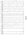
- FIG. 7 The design of 32-state, 180 degree rotationally invariant linear convolutional code with these sixteen 4D subsets is illustrated in Figs. 7 and 8.
- a rate 3/4, 32-state linear convolutional encoder 84 is used to generate four bits (YO n 11 n 12 n 13 n ) needed to specify the 4D subset from which a 4D point is to be drawn. (Note that the bit patterns in the YO n l1 n 12 n 13 n columns of Fig. 8 correspond to the decimal number for each 4D subset.)
- each box marked 2T represents a temporary storage element which holds any input value for two signaling intervals; the value held in the element always appears at its output.
- the circles marked plus are "exclusive or elements".
- the outputs of the 2T elements are bits marked W1 n , W2 n , W3 n , W4 n , and W5 n which together comprise the state of the finite state device represented by encoder 84.
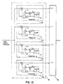
- Fig. 9 Only certain sequences of state transitions of the convolutional encoder are allowed as represented by the branches in the trellis diagram of Fig. 9.
- the 32 possible current states are represented by a column of dots 86 each marked with the corresponding pattern of state defining bits.
- the 32 possible next states are represented by column 88.
- Trellis branches 90 connecting current states to next states represent allowed state transitions (Only representative portions of the trellis are shown in Fig. 9. The entire trellis can be reconstructed from the chart of Fig. 10).
- Each state can be followed by only eight possible transitions.
- Each transition has a 4D subset assigned to it.
- the assignment for transitions from each current state are represented by the 4D subset numbers appearing in column 92 to the left of that state. For example, the eight transitions from current state 00000 are assigned 4D subsets 01452367 respectively, as shown in Fig. 10. Only the first three transitions are labeled in Fig. 9.
- a bit converter 96 converts the four bits (YO n , l1 n , 12 n , 13 n ) into two pairs of selection bits, ZO n Z1 n , and Z0 n+1 Z1 n+1 , which are used to select the pair of 2D subsets corresponding to the 4D subset.
- each pair of selection bits corresponds in a 2D subset in accordance with the following table:
- the eleven uncoded information bits which remain are used to select a particular 4D point from the previously selected 4D subset.
- a 4D block encoder 97 takes three of the remaining uncoded information bits (l1 n+1 , 12 n+1 , and 13 n+1 ) and generates two pairs of selection bits (Z2 n Z3 n and Z2 n+1 Z3 n+1 ). Each pair of those selection bits can assume any of the values 00, 01, or 10, but they cannot both assume the value 10.
- the first pair Z2 n Z3 n will be used to select the inner group or outer group of the first 2D subset corresponding to the previously selected 4D subset, likewise for the second pair Z2 n+1 Z3 n+1 with respect to the second 2D subset.
- the inner group is organized into two halves. If the pair of selection bits is 00, one of the halves of the inner group is selected; if the bits are 01, the other half of the inner group is selected; otherwise the outer group is selected.
- the first group Z4 n Z5 n Z6 n Z7 n will be used to select a 2D point from the previously selected outer group or the selected half of the inner group of the first 2D subset, and likewise for the second group Z4 n+1 Z5 n+1 Z6 n+1 Z7 n+1 .
- bit converter 96 and 4D block encoder 97 take the four output bits of the convolutional encoder and the eleven remaining uncoded information bits and produce sixteen coded selection bits. Those sixteen selection bits are then grouped by sampler 36 into two groups of eight selection bits each, Z2 n Z3 n Z4 n Z5 n Z6 n Z7 n ZO n Z1 n and Z2 n+1 Z3 n + 1 Z4 n + 1 Z5 n + 1 Z6 n + 1 Z7 n + 1 ZO n + 1 Z1 n+1 .
- the first group Z2 n Z3 n Z4 n Z5 n Z6 n Z7 n Z0 n Z1 n is then used to address a 2D mapping table 38 (constructed in the manner previously described) to obtain the pair of coordinates for the first 2D point corresponding to the 4D point defined by the four output bits of the convolutional encoder and the eleven remaining uncoded information bits.
- the second group of selection bits addresses the same table 38 to obtain the coordinates of the second 2D point.
- the pair of coordinate values corresponding to other patterns of ZO m Z1 can be obtained through 90 degree rotations of the pair of coordinates obtained for the specific pattern of ZO m Z1 m .
- sequence of signal points sent from encoder 26 carries with it information (in the form of the subsets from which those signal points were drawn) about the encoder's path through the trellis.
- decoder 48 exploits this historical information to estimate the path through the trellis which was likely to have been tranversed at the transmitter by also taking into account the noise correlation, and using that estimated path determines the signal points which were sent.
- the decoding process is based on a modification of the Viterbi decoding algorithm.
- the decoder stores for each of the possible thirty-two states a contending path history comprising the list of the L most recent 4D signal points lying on some likely trellis path which ends in that state. (2L is the number of signaling intervals -- for example -- which elapses between the time a signal is received and the time a corresponding final decision is made about which signal point was sent).
- the decoder also stores for each possible state a contending path metric which represents the aggregate squared distance between the 4D signal points on the contending path ending in that state and certain noise corrected versions (to be described below) of the sequence of received 4D signals.
- the decoder After two more signaling intervals have elapsed, the decoder extends the trellis to the next point in time along the trellis (e.g., the time represented by column 88 in Fig. 9). Extending the trellis is done in general by identifying the minimum metric contending trellis path ending in each next possible state based on the previously stored contending path metrics and on calculations of the squared distances (branch metrics) for alternative possible transitions (branches) leading to each next possible state. Once the trellis has been extended, the oldest 4D signal point in the most likely one of the contending path histories becomes a final decision. This process of extending the trellis is repeated every two signaling intervals.
- modifying circuitry 46 includes four noise predictors 102, 104, 106, 108, associated respectively with the four different 2D subsets A, B, C, D.
- predictor 104 is associated with 2D subset B.
- 2D subsets by integers according to:
- subsets associated with the predictors are the same as the subsets used in the encoder, in general the subsets used with the predictors can be different and thus will be called decision subsets while the subsets at the encoder will be called encoder subsets.
- Modifying circuitry 46 receives from the demodulator pairs of 2D received signals each pair corresponding to two intervals worth of bits encoded by the transmitter.
- the two received signals in each pair are delivered in sequence.
- the currently received pair are respectively denoted r 1 , new and r 2 , new
- the previous pair are denoted r 1 , old and r 2 , old .
- the order in which the signals are delivered is r 1 , old , r 2 , old , r 1 , new , r 2 , new .
- the same received signals are delivered to all of the predictors.
- the same predictor coefficient is used for both received signals of the currently received pair and is denoted b new .
- the coefficient is bold.
- the tentative decisions of which signals were sent in the current pair of intervals are respectively denoted ⁇ 1 ,new, C 2 , new and the tentative decisions for the prior pair of intervals are n ⁇ 1 ,old, C 2 , old . These decisions will be used in updating the predictor coefficient.
- the decoding for each pair of signaling intervals proceeds on an interval-by-interval basis.
- the first step is to update the predictor coefficient (b new ) to be used by all four predictors in both intervals of the pair (122).
- * represents the complex conjugate
- A is a positive constant.
- ⁇ 1 ,old and ⁇ 2 , old are the tentative decisions in the prior signaling intervals corresponding to the most recent signal points in the best path history with the minimum path metric.
- each predictor uses its noise prediction to modify (126) the currently received signal r i , new .
- the outputs of the modifying circuitry are then:
- 2D branch metrics are computed (128) for each modified received signal, namely the branch metrics for the signal points in the four 2D encoder subsets which are nearest to that modified point.
- the 16 branch metrics are saved.
- the 2D branch metrics saved in the first and second intervals are then combined (138) into a total of 64 4D branch metrics.
- Each 4D branch metric is the sum of one of the first interval 2D branch metrics and one of the second interval 2D branch metrics.
- Each of the 64 4D branch metrics is denoted where I represents the 4D subset corresponding to the 2D encoder subsets j and k.
- the 4D branch metric D 2 (1,i) is the sum of (a) the squared distance between the first interval output of the ith modifying circuitry, and the nearest 2D point from the first 2D encoder subset j corresponding to the Ith 4D subset, plus (b) the squared distance between the second interval output of the modifying circuitry associated with first 2D decision subset j corresponding to the Ith 4D subset, and the nearest 2D point from the second 2D encoder subset k corresponding to the Ith 4D subset.
- the 4D branch metric is a concatenation of two 2D branch metrics for the two signaling intervals.
- the 2D metrics are respectively based on the closest points from the two 2D encoder subsets making up the 4D subset. In the first interval the metric is measured from some i'th modified received signal; in the second interval from the modified received signal associated with the 2D decision subset of the first interval.
- the 64 4D branch metrics are then used to extend the trellis (140) by first assigning to each trellis branch an appropriate one of the 4D branch metrics. Specifically, a trellis branch to which a 4D subset I has been assigned and which originates from a state with a path history whose most recent 2D signal point is in 2D decision subset i will be assigned branch metrics D 2 (1,i). Once the branch metrics have been assigned, the extension of the trellis is accomplished in the usual way by finding the best contending paths with minimum accumulated metric ending in each possible next state.
- the most recent 4D signal point ⁇ 1 ,new C 2 , new in that path is saved to be used to update the predictor coefficient in the next signaling interval.
- the oldest 4D signal point in that path is released (144) as a final decision for delivery to converter 62 (Fig. 5).
- each 2D point of the pair of 2D points corresponding to the 4D point can first be mapped back to eight Z bits, using a single bit mapping table 64 (Fig. 4). Then performing the inverse conversions corresponding to the bit converter and 4D block encoder produces the 14 information bits.
- the number of noise predictors is not dependent on the number of states or the number of dimensions of the code. Only 16 possible branch metrics need to be calculated in each signaling interval, and only 64 4D metrics need to be calculated. With relatively few branch metric and noise prediction calculations to be made, the decoder can be relatively simple with no major sacrifice in performance.
- the code can be other than 4D, for example 2D, 8D, 16D, etc., and can have other numbers of states, for example, 8 states, 16 states, 64 states, etc.
- the noise predictors can be replaced by or combined with other feedback devices such as adaptive phase predictors.
- a baseband communication system can be used.
- the modifying circuitry may use a finer or coarser partitioning of the 2D signal constellation than the partitioning used in the encoder. For example, in the 32-state code, the modifying circuitry may partition the 192-point 2D signal constellation into 8 decision subsets with 24 points in each decision subset again keeping the distance between points in a decision subset as large as possible. In this case, 8 noise predictions and 8 modified versions of the received signal will be generated. For each modified version, 4 2D branch metrics are computed with respect to each of the 2D encoder subsets A,B,C, and D.
- a trellis branch to which a 4D subset I has been assigned and which originates from a state with a path history whose most recent 2D signal point is in the 2D decision subset i (0-7) will be assigned the branch metrics D 2 (1,i). Otherwise, the decoding proceeds in the same manner as described above.
- the scheme can also be used with multiple predictor coefficients.
- the decision subsets will be multi-dimensional.
- the 16 4D encoder subsets as the decision subsets.
- each signaling interval 16 4D alternative decisions are formed.
- a trellis branch to which a 4D subset i has been assigned and which originates from a state with a path history whose most recent pair of signal points is in the 4D decision subset 1 (0-15) will be assigned the branch metrics D 2 (1,i).
- the trellis update can otherwise proceed in the same manner as described before.
- the decision subsets can be different from the encoder subsets. For example in principle, only 8 decision subsets need be used.
- the decoder may employ a larger number of states than required by the encoder, to achieve improved performance.
- each current encoder state can be replaced by 4 new decoder states based on the most recent 2D decision subsets. More specifically, when the decision subsets are the same as the 2D encoder subsets, the new decoder states can be denoted as (i,a), (i,b), (i,c) and (i,d), where i (0-31) represents the encoder state and a,b,c, or d represent the 2D decision subset associated with the most recent signal point in a trellis path.
- the state transition diagram for this new decoder state assignment can be easily obtained from Fig. 10.
- the state (k,j) with k (0-31) being an encoder state and j (a,b,c, or d) a 2D decision subset will have transitions from decoder states (n,a), (n,b), (n,c), (n,d) and (m,a), (m,b), (m,c), (m,d) with n and m representing the two encoder states which have a transition to encoder state k corresponding to a 4D subset the second 2D subset of which is j.
- the transitions to state (0,a) will be as shown in Fig. 14.
- contending path metrics and path histories will be stored.
- the generation of the four modified versions of the received signal and the calculation of 64 4D branch metrics will be the same.
- the trellis update can proceed in a similar manner.
- the new path metric for state (0,a) will be the minimum accumulated path metric of all contending paths shown in Fig. 14 leading to state (0,a).
- the tentative decisions ê 1 , new and f 2 , new and the final decisions are again obtained from the best path history with the smallest path metric.
- the set partitioning used in the decoder can again be different from the partitioning used in the encoder. In the special case when the number of decision subsets is equal to the number of signal points, the decoder will become optimum for the single-coefficient case.
- the method can be applied for codes with any number of states or dimensions. It can also be used in conjunction with the Qureshi scheme, by modifying received signals with alternative decisions taken directly from path histories or previous branch metric computations. Multiple predictor coefficients can be handled by defining states in terms of multi-dimensional decision subsets.
- This method can also be used to implement a reduced-state Viterbi algorithm detector in an uncoded system with channel distortion.
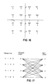
- a stream of binary digits 160 are collected in groups of four by serial-to-parallel converter 162 and encoded in the mapping device 164 at the signaling rate into a complex signal point according to the signal point mapping shown in Fig. 16.
- the signal points are modulated, filtered in a transmit filter and D/A converted 166 to generate an analog signal to be sent over a bandlimited, noise-affected channel.
- the noise-affected signal is A/D converted and passed through a linear equalizer 168 to generate a sequence of received signals at the signaling rate.
- the received sequence is fed into modifying circuitry 170 which partitions the signal constellation into four decision subsets according to Fig. 16.
- the modifying circuitry When a new signal r new is received the modifying circuitry generates an alternative decision for each subset by choosing the signal points in the subset which are closest to r new in the sense of Euclidean distance.
- ênew(i), i 0,1,2,3.
- the received signal r new is modified using alternative decisions from the previous signaling interval: where b 1 , new is the predictor coefficient.
- b 1 new is the predictor coefficient.
- These four modified received signals are fed into Viterbi algorithm device 172.
- the Viterbi algorithm has only four states defined in terms of the decision subsets.
- the associated state transition diagram is shown in Fig. 17. Here, four transitions are indicated for each state. Each transition is associated with a decision subset and each actually represents four possible transitions associated with the four signal points in that subset.
- the predictor coefficient can be adaptively updated using tentative decisions from the Viterbi algorithm.
- the methods for exploiting noise correlation at the output of a linear equalizer can also be used in other forms of DFE or Viterbi detectors. Other approaches for updating the predictor coefficients can be used.
Landscapes
- Engineering & Computer Science (AREA)
- Computer Networks & Wireless Communication (AREA)
- Signal Processing (AREA)
- Artificial Intelligence (AREA)
- Physics & Mathematics (AREA)
- Probability & Statistics with Applications (AREA)
- Theoretical Computer Science (AREA)
- Power Engineering (AREA)
- Error Detection And Correction (AREA)
- Digital Transmission Methods That Use Modulated Carrier Waves (AREA)
Claims (14)
gekennzeichnet durch
Applications Claiming Priority (2)
| Application Number | Priority Date | Filing Date | Title |
|---|---|---|---|
| US746538 | 1985-06-19 | ||
| US06/746,538 US4713829A (en) | 1985-06-19 | 1985-06-19 | Coded modulation system with a simplified decoder capable of reducing the effects of channel distortion |
Publications (3)
| Publication Number | Publication Date |
|---|---|
| EP0206770A2 EP0206770A2 (de) | 1986-12-30 |
| EP0206770A3 EP0206770A3 (en) | 1988-09-28 |
| EP0206770B1 true EP0206770B1 (de) | 1993-01-27 |
Family
ID=25001276
Family Applications (1)
| Application Number | Title | Priority Date | Filing Date |
|---|---|---|---|
| EP86304724A Expired - Lifetime EP0206770B1 (de) | 1985-06-19 | 1986-06-19 | Kodiertes Modulationssystem mit einem vereinfachten Dekoder, fähig zur Verminderung der Folge der Kanalverzerrung |
Country Status (3)
| Country | Link |
|---|---|
| US (1) | US4713829A (de) |
| EP (1) | EP0206770B1 (de) |
| DE (1) | DE3687603T2 (de) |
Families Citing this family (37)
| Publication number | Priority date | Publication date | Assignee | Title |
|---|---|---|---|---|
| US4833693A (en) * | 1985-11-21 | 1989-05-23 | Codex Corporation | Coded modulation system using interleaving for decision-feedback equalization |
| GB2215567B (en) * | 1988-03-05 | 1992-11-18 | Plessey Co Plc | Improvements in or relating to equalisers |
| US5159610A (en) * | 1989-05-12 | 1992-10-27 | Codex Corporation | Trellis precoding for modulation systems |
| US4941154A (en) * | 1989-05-30 | 1990-07-10 | At&T Bell Laboratories | Trellis coding method and arrangement for fractional bit rates |
| US5128967A (en) * | 1989-07-24 | 1992-07-07 | Motorola, Inc. | Symbol state trellis maximum likelihood detection method |
| GB9008613D0 (en) * | 1990-04-17 | 1990-06-13 | Marconi Gec Ltd | Reducing interference in r.f.signals |
| FI85548C (fi) * | 1990-06-14 | 1992-04-27 | Nokia Oy Ab | Mottagningsfoerfarande och mottagare foer diskreta signaler. |
| SG44761A1 (en) * | 1991-01-09 | 1997-12-19 | Philips Electronics Uk Ltd | Signal transmission system |
| US5249200A (en) * | 1991-07-30 | 1993-09-28 | Codex Corporation | Device and method for combining precoding with symbol-rate spectral shaping |
| US5311557A (en) * | 1992-07-10 | 1994-05-10 | At&T Bell Laboratories | Circular limiter for use in a receiver to reduce the effects of signal distortion |
| US5995539A (en) * | 1993-03-17 | 1999-11-30 | Miller; William J. | Method and apparatus for signal transmission and reception |
| EP0677967A3 (de) * | 1994-04-12 | 1997-07-23 | Gold Star Co | Viterbi-Dekoder für hochauflösendes Fernsehen. |
| DE69535160T2 (de) * | 1995-09-18 | 2007-06-28 | Hitachi Global Storage Technologies Netherlands B.V. | Vorrichtung und verfahren zur rauschvorhersagenden maximal-wahrscheinlichkeitsdetektion |
| JP3475627B2 (ja) * | 1995-12-22 | 2003-12-08 | ソニー株式会社 | ディジタル信号再生装置および再生方法 |
| US5742622A (en) * | 1996-03-12 | 1998-04-21 | Discovision Associates | Error detection and correction system for a stream of encoded data |
| GB2319148B (en) * | 1996-09-27 | 1999-01-13 | Plessey Telecomm | Noise level determination |
| GB9622540D0 (en) * | 1996-10-30 | 1997-01-08 | Discovision Ass | Trackback for viterbi decoder |
| KR100241890B1 (ko) * | 1997-01-10 | 2000-03-02 | 윤종용 | 디지털 통신 시스템에서 간섭 제거 회로 |
| DE19803235A1 (de) * | 1998-01-28 | 1999-07-29 | Siemens Ag | Vorrichtung und Verfahren zur Veränderung des Rauschverhaltens in einem Empfänger eines Datenübertragungssystems |
| DE69922405T2 (de) * | 1998-11-09 | 2006-01-12 | Broadcom Corp., Irvine | Verfahren und system zur entscheidungrückgekoppelten dekodierung |
| US6477200B1 (en) | 1998-11-09 | 2002-11-05 | Broadcom Corporation | Multi-pair gigabit ethernet transceiver |
| US6249544B1 (en) | 1998-11-13 | 2001-06-19 | Broadcom Corporation | System and method for high-speed decoding and ISI compensation in a multi-pair transceiver system |
| AU1725900A (en) * | 1998-11-13 | 2000-06-05 | Broadcom Corporation | Demodulator for a multi-pair gigabit transceiver |
| US6253345B1 (en) | 1998-11-13 | 2001-06-26 | Broadcom Corporation | System and method for trellis decoding in a multi-pair transceiver system |
| US6201831B1 (en) | 1998-11-13 | 2001-03-13 | Broadcom Corporation | Demodulator for a multi-pair gigabit transceiver |
| US6252904B1 (en) | 1998-11-13 | 2001-06-26 | Broadcom Corporation | High-speed decoder for a multi-pair gigabit transceiver |
| US6226332B1 (en) | 1998-11-13 | 2001-05-01 | Broadcom Corporation | Multi-pair transceiver decoder system with low computation slicer |
| DE60035679T2 (de) * | 1999-04-22 | 2008-06-05 | Broadcom Corp., Irvine | Gigabit-ethernt mit zeitverschiebungen zwischen verdrillten leitungspaaren |
| FI110825B (fi) * | 1999-08-10 | 2003-03-31 | Nokia Corp | Menetelmä modulaationilmaisimen valintaan vastaanottimessa ja vastaanotin |
| US7058422B2 (en) * | 2000-09-20 | 2006-06-06 | Bae Systems Information And Electronic Systems Integration Inc. | Method for overusing frequencies to permit simultaneous transmission of signals from two or more users on the same frequency and time slot |
| JP3794622B2 (ja) * | 2001-03-06 | 2006-07-05 | 独立行政法人情報通信研究機構 | 受信装置、受信方法、プログラム、ならびに、情報記録媒体 |
| US6735264B2 (en) | 2001-08-31 | 2004-05-11 | Rainmaker Technologies, Inc. | Compensation for non-linear distortion in a modem receiver |
| US7173966B2 (en) * | 2001-08-31 | 2007-02-06 | Broadband Physics, Inc. | Compensation for non-linear distortion in a modem receiver |
| US8095857B2 (en) * | 2001-12-18 | 2012-01-10 | Agere Systems Inc. | Method and apparatus for joint equalization and decoding of multidimensional codes transmitted over multiple symbol durations |
| US7613985B2 (en) * | 2003-10-24 | 2009-11-03 | Ikanos Communications, Inc. | Hierarchical trellis coded modulation |
| US20070211840A1 (en) | 2006-02-17 | 2007-09-13 | International Business Machines Corporation | Methods and apparatus for analyzing transmission lines with decoupling of connectors and other circuit elements |
| US9660845B2 (en) * | 2015-10-06 | 2017-05-23 | Huawei Technologies Co., Ltd. | System and method for state reduction in trellis equalizers using bounded state enumeration |
Citations (2)
| Publication number | Priority date | Publication date | Assignee | Title |
|---|---|---|---|---|
| EP0200505A2 (de) * | 1985-04-25 | 1986-11-05 | Codex Corporation | Gerät zur Übertragung von Datenbitgruppen und Verfahren zur Beurteilung der mit der grössten Wahrscheinlichkeit übertragenen Sequenz |
| US4631735A (en) * | 1984-12-28 | 1986-12-23 | Codex Corporation | Coded modulation system with feedback |
Family Cites Families (13)
| Publication number | Priority date | Publication date | Assignee | Title |
|---|---|---|---|---|
| US727398A (en) | 1903-03-10 | 1903-05-05 | Eagle Pencil Co | Rubber-tip attachment for lead-pencils. |
| CH609510A5 (de) * | 1976-06-18 | 1979-02-28 | Ibm | |
| US4084137A (en) * | 1976-08-24 | 1978-04-11 | Communications Satellite Corporation | Multidimensional code communication systems |
| EP0054583B1 (de) * | 1980-12-23 | 1984-03-07 | International Business Machines Corporation | Verfahren zur Übertragung binärer Datenfolgen und Einrichtung zur schnellen Ermittlung des Endes einer übertragenen binären Datenfolge |
| GB2118003B (en) * | 1982-02-02 | 1985-07-31 | Racal Milgo Ltd | Differential encoder and decoder for transmitting binary data |
| US4562426A (en) * | 1982-11-08 | 1985-12-31 | Codex Corporation | Symbol coding apparatus |
| US4534040A (en) * | 1983-01-04 | 1985-08-06 | At&T Information Systems | Method and apparatus for coding a binary signal |
| US4483012A (en) * | 1983-04-18 | 1984-11-13 | At&T Information Systems | Differentially convolutional channel coding with expanded set of signalling alphabets |
| US4520490A (en) * | 1983-08-05 | 1985-05-28 | At&T Information Systems Inc. | Differentially nonlinear convolutional channel coding with expanded set of signalling alphabets |
| US4601044A (en) * | 1983-11-04 | 1986-07-15 | Racal Data Communications Inc. | Carrier-phase adjustment using absolute phase detector |
| US4583236A (en) * | 1983-11-04 | 1986-04-15 | Racal Data Communications Inc. | Modified absolute phase detector |
| US4586182A (en) * | 1984-02-06 | 1986-04-29 | Codex Corporation | Source coded modulation system |
| US4581601A (en) * | 1984-06-25 | 1986-04-08 | At&T Bell Laboratories | Multi-dimensional coding for error reduction |
-
1985
- 1985-06-19 US US06/746,538 patent/US4713829A/en not_active Expired - Lifetime
-
1986
- 1986-06-19 DE DE8686304724T patent/DE3687603T2/de not_active Expired - Fee Related
- 1986-06-19 EP EP86304724A patent/EP0206770B1/de not_active Expired - Lifetime
Patent Citations (2)
| Publication number | Priority date | Publication date | Assignee | Title |
|---|---|---|---|---|
| US4631735A (en) * | 1984-12-28 | 1986-12-23 | Codex Corporation | Coded modulation system with feedback |
| EP0200505A2 (de) * | 1985-04-25 | 1986-11-05 | Codex Corporation | Gerät zur Übertragung von Datenbitgruppen und Verfahren zur Beurteilung der mit der grössten Wahrscheinlichkeit übertragenen Sequenz |
Non-Patent Citations (1)
| Title |
|---|
| IEEE GLOBAL TELECOMMUNICATIONS CONFERENCE, San Diego, California, 28th November - 1st December 1983, Globecom 83, conference record, vol. 2, pages 1032-1038, IEEE, New York, US; R. FANG et al.: "Four-dimensionally coded PSK systems for combatting effects of severe ISI and CCI" * |
Also Published As
| Publication number | Publication date |
|---|---|
| US4713829A (en) | 1987-12-15 |
| EP0206770A3 (en) | 1988-09-28 |
| DE3687603T2 (de) | 1993-05-19 |
| DE3687603D1 (de) | 1993-03-11 |
| EP0206770A2 (de) | 1986-12-30 |
Similar Documents
| Publication | Publication Date | Title |
|---|---|---|
| EP0206770B1 (de) | Kodiertes Modulationssystem mit einem vereinfachten Dekoder, fähig zur Verminderung der Folge der Kanalverzerrung | |
| US5159610A (en) | Trellis precoding for modulation systems | |
| US5455839A (en) | Device and method for precoding | |
| EP0523816B1 (de) | Gerät zur Übertragung von Datenbitgruppen und Verfahren zur Beurteilung der mit der grössten Wahrscheinlichkeit übertragenen Sequenz | |
| EP0624018B1 (de) | Rotationsinvariante Mehrpegelkodierungssysteme | |
| CA2030038C (en) | Coded modulation for mobile radio | |
| KR100262426B1 (ko) | 송신기 장치, 수신기 장치 및 다레벨 코드화 변조 방법 | |
| US5289501A (en) | Coded modulation with unequal error protection for fading channels | |
| JP3685269B2 (ja) | 透明2進畳み込み符号を組み入れた回転不変トレリスコーダ及び方法 | |
| EP0536948B1 (de) | Mehrdimensionale, trelliskodierte Modulation für Schwundkanäle | |
| US6178209B1 (en) | Method of estimating trellis encoded symbols utilizing simplified trellis decoding | |
| EP0154415B1 (de) | Kodiertes Modulationssystem | |
| CA2115946C (en) | Multidimensional trellis-coded communication system | |
| US8635516B2 (en) | Method and apparatus for joint equalization and decoding of multidimensional codes transmitted over multiple symbol durations | |
| US4755998A (en) | Coded modulation system | |
| Gersho et al. | Multidimensional signal constellations for voiceband data transmission | |
| EP0397537B1 (de) | Abbildung von digitalen Datenfolgen für die Datenübertragung | |
| US6421395B1 (en) | Termination of coded or uncoded modulation with path-oriented decoder | |
| HK1008717B (en) | Mapping digital data sequences for data transmission | |
| Carden | A Quantized Euclidean Soft-Decision Maximum Likelihood Sequence Decoder: A Concept for Spectrally Efficient TM Systems | |
| JP3074533B1 (ja) | データ伝送システム | |
| Kerpez | Viterbi receivers in the presence of severe intersymbol interference | |
| Fagan et al. | Performance comparison of detection methods derived from maximum-likelihood sequence estimation | |
| Kohno et al. | An automatic equalizer including a Viterbi decoder for trellis coded modulation system | |
| Zhou et al. | Coded reduced-bandwidth QAM with decision-feedback equalization |
Legal Events
| Date | Code | Title | Description |
|---|---|---|---|
| PUAI | Public reference made under article 153(3) epc to a published international application that has entered the european phase |
Free format text: ORIGINAL CODE: 0009012 |
|
| AK | Designated contracting states |
Kind code of ref document: A2 Designated state(s): BE CH DE FR GB IT LI NL SE |
|
| PUAL | Search report despatched |
Free format text: ORIGINAL CODE: 0009013 |
|
| AK | Designated contracting states |
Kind code of ref document: A3 Designated state(s): BE CH DE FR GB IT LI NL SE |
|
| 17P | Request for examination filed |
Effective date: 19890310 |
|
| 17Q | First examination report despatched |
Effective date: 19900914 |
|
| GRAA | (expected) grant |
Free format text: ORIGINAL CODE: 0009210 |
|
| AK | Designated contracting states |
Kind code of ref document: B1 Designated state(s): BE CH DE FR GB IT LI NL SE |
|
| PG25 | Lapsed in a contracting state [announced via postgrant information from national office to epo] |
Ref country code: IT Free format text: LAPSE BECAUSE OF FAILURE TO SUBMIT A TRANSLATION OF THE DESCRIPTION OR TO PAY THE FEE WITHIN THE PRE;WARNING: LAPSES OF ITALIAN PATENTS WITH EFFECTIVE DATE BEFORE 2007 MAY HAVE OCCURRED AT ANY TIME BEFORE 2007. THE CORRECT EFFECTIVE DATE MAY BE DIFFERENT FROM THE ONE RECORDED.SCRIBED TIME-LIMIT Effective date: 19930127 Ref country code: CH Effective date: 19930127 Ref country code: SE Effective date: 19930127 Ref country code: LI Effective date: 19930127 |
|
| REF | Corresponds to: |
Ref document number: 3687603 Country of ref document: DE Date of ref document: 19930311 |
|
| REG | Reference to a national code |
Ref country code: CH Ref legal event code: PL |
|
| ET | Fr: translation filed | ||
| PLBE | No opposition filed within time limit |
Free format text: ORIGINAL CODE: 0009261 |
|
| STAA | Information on the status of an ep patent application or granted ep patent |
Free format text: STATUS: NO OPPOSITION FILED WITHIN TIME LIMIT |
|
| 26N | No opposition filed | ||
| PGFP | Annual fee paid to national office [announced via postgrant information from national office to epo] |
Ref country code: BE Payment date: 19980428 Year of fee payment: 13 |
|
| PG25 | Lapsed in a contracting state [announced via postgrant information from national office to epo] |
Ref country code: BE Free format text: LAPSE BECAUSE OF NON-PAYMENT OF DUE FEES Effective date: 19990630 |
|
| BERE | Be: lapsed |
Owner name: CODEX CORP. Effective date: 19990630 |
|
| PGFP | Annual fee paid to national office [announced via postgrant information from national office to epo] |
Ref country code: NL Payment date: 20010319 Year of fee payment: 16 |
|
| PGFP | Annual fee paid to national office [announced via postgrant information from national office to epo] |
Ref country code: GB Payment date: 20010502 Year of fee payment: 16 |
|
| PGFP | Annual fee paid to national office [announced via postgrant information from national office to epo] |
Ref country code: FR Payment date: 20010531 Year of fee payment: 16 |
|
| PGFP | Annual fee paid to national office [announced via postgrant information from national office to epo] |
Ref country code: DE Payment date: 20010627 Year of fee payment: 16 |
|
| REG | Reference to a national code |
Ref country code: GB Ref legal event code: IF02 |
|
| PG25 | Lapsed in a contracting state [announced via postgrant information from national office to epo] |
Ref country code: GB Free format text: LAPSE BECAUSE OF NON-PAYMENT OF DUE FEES Effective date: 20020619 |
|
| PG25 | Lapsed in a contracting state [announced via postgrant information from national office to epo] |
Ref country code: DE Free format text: LAPSE BECAUSE OF NON-PAYMENT OF DUE FEES Effective date: 20030101 Ref country code: NL Free format text: LAPSE BECAUSE OF NON-PAYMENT OF DUE FEES Effective date: 20030101 |
|
| GBPC | Gb: european patent ceased through non-payment of renewal fee |
Effective date: 20020619 |
|
| PG25 | Lapsed in a contracting state [announced via postgrant information from national office to epo] |
Ref country code: FR Free format text: LAPSE BECAUSE OF NON-PAYMENT OF DUE FEES Effective date: 20030228 |
|
| NLV4 | Nl: lapsed or anulled due to non-payment of the annual fee |
Effective date: 20030101 |
|
| REG | Reference to a national code |
Ref country code: FR Ref legal event code: ST |
|
| P01 | Opt-out of the competence of the unified patent court (upc) registered |
Effective date: 20230520 |