EP0206597B1 - Improvements in or relating to infra-red heaters - Google Patents
Improvements in or relating to infra-red heaters Download PDFInfo
- Publication number
- EP0206597B1 EP0206597B1 EP86304318A EP86304318A EP0206597B1 EP 0206597 B1 EP0206597 B1 EP 0206597B1 EP 86304318 A EP86304318 A EP 86304318A EP 86304318 A EP86304318 A EP 86304318A EP 0206597 B1 EP0206597 B1 EP 0206597B1
- Authority
- EP
- European Patent Office
- Prior art keywords
- infra
- red
- heating element
- heater according
- base layer
- Prior art date
- Legal status (The legal status is an assumption and is not a legal conclusion. Google has not performed a legal analysis and makes no representation as to the accuracy of the status listed.)
- Expired - Lifetime
Links
- 230000002093 peripheral effect Effects 0.000 claims abstract description 20
- 125000004122 cyclic group Chemical group 0.000 claims abstract description 14
- 239000002241 glass-ceramic Substances 0.000 claims abstract description 14
- 239000011810 insulating material Substances 0.000 claims abstract description 10
- 238000010438 heat treatment Methods 0.000 claims description 56
- 239000012774 insulation material Substances 0.000 claims description 16
- 238000009826 distribution Methods 0.000 claims description 9
- 239000011248 coating agent Substances 0.000 claims description 4
- 238000000576 coating method Methods 0.000 claims description 4
- 238000010411 cooking Methods 0.000 abstract description 12
- 239000002184 metal Substances 0.000 description 5
- 239000000919 ceramic Substances 0.000 description 4
- 230000005855 radiation Effects 0.000 description 4
- 238000009835 boiling Methods 0.000 description 3
- 239000000835 fiber Substances 0.000 description 3
- 239000000463 material Substances 0.000 description 3
- 238000001816 cooling Methods 0.000 description 2
- 229910021485 fumed silica Inorganic materials 0.000 description 2
- 230000001351 cycling effect Effects 0.000 description 1
- 230000007423 decrease Effects 0.000 description 1
- 230000000994 depressogenic effect Effects 0.000 description 1
- 230000000694 effects Effects 0.000 description 1
- 230000008030 elimination Effects 0.000 description 1
- 238000003379 elimination reaction Methods 0.000 description 1
- 230000014759 maintenance of location Effects 0.000 description 1
- 230000001681 protective effect Effects 0.000 description 1
- 230000001105 regulatory effect Effects 0.000 description 1
- 238000009827 uniform distribution Methods 0.000 description 1
- 238000010792 warming Methods 0.000 description 1
Images


Classifications
-
- F—MECHANICAL ENGINEERING; LIGHTING; HEATING; WEAPONS; BLASTING
- F24—HEATING; RANGES; VENTILATING
- F24C—DOMESTIC STOVES OR RANGES ; DETAILS OF DOMESTIC STOVES OR RANGES, OF GENERAL APPLICATION
- F24C15/00—Details
- F24C15/10—Tops, e.g. hot plates; Rings
- F24C15/102—Tops, e.g. hot plates; Rings electrically heated
- F24C15/106—Tops, e.g. hot plates; Rings electrically heated electric circuits
-
- H—ELECTRICITY
- H05—ELECTRIC TECHNIQUES NOT OTHERWISE PROVIDED FOR
- H05B—ELECTRIC HEATING; ELECTRIC LIGHT SOURCES NOT OTHERWISE PROVIDED FOR; CIRCUIT ARRANGEMENTS FOR ELECTRIC LIGHT SOURCES, IN GENERAL
- H05B3/00—Ohmic-resistance heating
- H05B3/68—Heating arrangements specially adapted for cooking plates or analogous hot-plates
- H05B3/74—Non-metallic plates, e.g. vitroceramic, ceramic or glassceramic hobs, also including power or control circuits
- H05B3/742—Plates having both lamps and resistive heating elements
-
- H—ELECTRICITY
- H05—ELECTRIC TECHNIQUES NOT OTHERWISE PROVIDED FOR
- H05B—ELECTRIC HEATING; ELECTRIC LIGHT SOURCES NOT OTHERWISE PROVIDED FOR; CIRCUIT ARRANGEMENTS FOR ELECTRIC LIGHT SOURCES, IN GENERAL
- H05B3/00—Ohmic-resistance heating
- H05B3/68—Heating arrangements specially adapted for cooking plates or analogous hot-plates
- H05B3/74—Non-metallic plates, e.g. vitroceramic, ceramic or glassceramic hobs, also including power or control circuits
- H05B3/744—Lamps as heat source, i.e. heating elements with protective gas envelope, e.g. halogen lamps
-
- H—ELECTRICITY
- H05—ELECTRIC TECHNIQUES NOT OTHERWISE PROVIDED FOR
- H05B—ELECTRIC HEATING; ELECTRIC LIGHT SOURCES NOT OTHERWISE PROVIDED FOR; CIRCUIT ARRANGEMENTS FOR ELECTRIC LIGHT SOURCES, IN GENERAL
- H05B2213/00—Aspects relating both to resistive heating and to induction heating, covered by H05B3/00 and H05B6/00
- H05B2213/04—Heating plates with overheat protection means
Definitions
- the cycle when a cyclic energy regulator is at a low setting, for example for simmering, the cycle will consist of a short on-period of full power followed by a long off-period and, due to the fast response of infra-red lamps compared with conventional resistance wire elements, can raise the contents of a cooking utensil to boiling point for a short period followed by a long cooling period instead of giving a continuous simmering condition.
- the infra-red heater 1 comprises a base layer of thermal insulation material , such as a microporous thermal insulation material based on pyrogenic silica or ceramic fibre, and a peripheral ring of insulation material which, in use, prevents heat escaping between the base layer and the underside of the glass ceramic cooking surface (not shown in Figure 1).
- the base layer, and if desired the peripheral ring, may be supported in a metal dish.
Landscapes
- Engineering & Computer Science (AREA)
- Chemical & Material Sciences (AREA)
- Ceramic Engineering (AREA)
- Combustion & Propulsion (AREA)
- Mechanical Engineering (AREA)
- General Engineering & Computer Science (AREA)
- Resistance Heating (AREA)
- Electric Stoves And Ranges (AREA)
- Control Of Resistance Heating (AREA)
- Electric Ovens (AREA)
Abstract
Description
- The present invention relates to infra-red heaters which incorporate at least one infra-red lamp.
- It is well known to use cyclic energy regulators (e.g. EP-
A-0 103 741) and multi-position electromechanical switches in order to control the energy output of the resistance element of conventional radiant heaters for use in glass ceramic top cookers. It is also known to use multi-position electromechanical switches to control infra-red heaters which incorporate a number of infra-red lamps (e.g. EP-A-0 117 346). However, the use of multi-position switches requires a number of series and parallel interconnections of the infra-red lamps in order to obtain a useful range of energy outputs and in practice this requires that the infra-red heater incorporates at least three infra-red lamps. - A considerable proportion of the cost of such infra-red heaters is attributable to the lamps. It is therefore desirable to reduce the number of lamps in the heater in order to reduce costs. However, it becomes difficult to provide an effective control of the energy output with a reduced number of lamps.
- Multi-position switches become impractical as the number of lamps is reduced and cyclic energy regulators also present a number of problems. For example, the electrical resistance of the filament of infra-red lamps is very low at ambient temperatures and this gives rise to high inrush currents when the lamp is energised which results in a high loading on the energy regulator contacts and can overload the domestic wiring system, thus tripping the protective circuit breaker. Further, an infra-red lamp has a high visible light output which gives rise to a disturbing flashing if the lamp is repeatedly turned on and off. Moreover, when a cyclic energy regulator is at a low setting, for example for simmering, the cycle will consist of a short on-period of full power followed by a long off-period and, due to the fast response of infra-red lamps compared with conventional resistance wire elements, can raise the contents of a cooking utensil to boiling point for a short period followed by a long cooling period instead of giving a continuous simmering condition.
- It has also been proposed to reduce the number of lamps by employing an electronic energy regulator, but electronic controls are themselves expensive and can be unreliable in the demanding environment of an electric cooker.
- EP-A-0 120 639 shows a radiant heater which incorporates four infra-red lamps that are positioned so as to be parallel to each other.
- DE-U-84 05 562.6 shows a heater which incorporates a high-temperature radiation heating element and a conventional heating element. In use the high-temperature heating elements can be energised continuously, while the conventional heating elements are energised separately with regulated and/or controlled electrical energy.
- EP-A-0 176 027, which was published after the priority date of the present application, shows a radiant heater with a light radiator heating element and a dark radiator heating element which can be switched on simultaneously and/or alternately with the light radiator heating element. The dark radiator heating element is arranged in the central region of the radiant heater, the central region being surrounded by an annular region containing the light radiator heating elements. Alternatively, if a uniform distribution of the light radiator heating elements over the entire cooking surface is desired, areas provided with dark radiator heating elements can be arranged between the light radiator heating elements.
- EP-
A-0 117 346 shows an infra-red heater for a glass ceramic top cooker, in which the heater comprises a dish, a base layer of thermal insulating material supported in the dish, a peripheral wall of thermal insulating material extending around the periphery of the base layer, a thermal cut-out device, and at least one infra-red heating element as mentioned in the preamble of claim 1. - EP-A-0 103 741 describes a heater in which conventional heating elements are connected in various configurations.
- EP-A-0 164 900, which was published after the priority date of the present application, shows a heating apparatus incorporating four infra-red lamps which can be connected in various series and parallel configurations in order to give a range of power outputs. According to Figures 3a and 3b, in the third lowest and lowest power outputs an additional element, such as a fifth lamp filament or a conventional heating element, is connected in series with the configuration formed by the lamp filaments. A further use of the additional element may be as a pre-heating device to produce faster warm-up periods of the apparatus.
- It is an object of the present invention to provide an infra-red heater which incorporates at least one infra-red lamp and which overcomes the above-mentioned disadvantages when used in conjunction with a cyclic energy regulator.
- According to the present invention there is provided an infra-red heater for a glass ceramic top cooker, which heater comprises a dish, a base layer of thermal insulating material supported in the dish, a peripheral wall of thermal insulating material extending around the periphery of the base layer, a thermal cut-out device, and at least one infra-red heating element having a high inrush current upon energisation and extending across the base layer, wherein a ballast device extending around and confined to the peripheral region of the heater is always electrically connected in series with the at least one heating element at least upon energisation of that element so as to limit the inrush current.
- The heater may be combined with a cyclic energy regulator, which regulator at its full power setting may connect the at least one heating element directly with its power source.
- The ballast device may comprise a coil of bare wire in the form of a ballast resistor. The ballast resistor may have an electrical resistance approximately half the resistance at operating temperature of the at least one heating element. The ballast resistor may comprise two coils of bare wire electrically connected in parallel. The coil comprising the ballast resistor may be straightened in regions where the coil passes adjacent to the at least one heating element.
- A further heating element may be arranged adjacent to or around the peripheral wall, a further peripheral wall extending around the further heating element. The further heating element may comprise an infra-red heating element having a high inrush current upon energisation and having a ballast resistor electrically connected in series with it. Alternatively, the further heating element may comprise a coil of bare wire.
- The surface of the base layer of thermal insulation material may be contoured so as to influence the temperature distribution across the heater. The base layer of thermal insulating material may have two depressions separated from each other by a central ridge.
- The heating element may comprise an infra-red lamp. The end portions of the lamp may have an opaque coating.
- Where the infra-red heating element comprises two infra-red lamps, the ballast device may comprise at least one coil of electrical resistance wire straightened in regions where the coil passes adjacent the lamps, the base layer of thermal insulation material having two shallow depressions each extending under a respective one of said lamps so as to influence the temperature distribution across the heater, said depressions being separated by a central ridge in the base layer.
- For a better understanding of the present invention and to show more clearly how it may be carried into effect reference will now be made, by way of example, to the accompanying drawings in which:
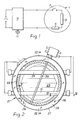
- Figure 1 is a diagrammatic representation of a first embodiment of an infra-red heater according to the present invention, together with a cyclic energy regulator;
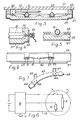
- Figure 2 is a plan view of a second embodiment of an infra-red heater according to the present invention;
- Figure 3 is a cross-sectional view taken along the line III-III shown in Figure 2;
- Figure 4 is a cross-sectional view taken along the line IV-IV shown in Figure 2;
- Figure 5 is a cross-sectional view taken along the line V-V shown in Figure 2;
- Figure 6 is a side view of an infra-red heater according to the present invention showing a spring wire fastening clip;
- Figure 7 is an exploded perspective view of an alternative fastening clip;
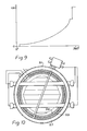
- Figure 8 is a diagrammatic representation of a third embodiment of an infra-red heater according to the present invention, together with a cyclic energy regulator;
- Figure 9 is a graph showing the energy output of the heater illustrated in Figure 8 as a function of the angular position of the energy regulator control knob;
- Figure 10 is a plan view of a fourth embodiment of an infra-red heater according to the present invention;
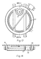
- Figure 11 is a plan view of a fifth embodiment of an infra-red heater according to the present invention;
- Figure 12 is a cross-sectional view taken along the line XII-XII shown in Figure 11;
- Figure 13 is a plan view of a sixth embodiment of an infra-red heater according to the present invention;
- Figure 14 is a sectional view taken along the line XIV-XIV shown in Figure 13;
- Figure 15 is a diagrammatic representation of a seventh embodiment of an infra-red heater according to the present invention, together with a cyclic energy regulator;
- Figure 16 is a diagrammatic representation of an eighth embodiment of an infra-red heater according to the present invention, together with a cyclic energy regulator;
- Figure 17 is a plan view of the infra-red heater represented diagrammatically in Figure 16; and
- Figure 18 is a cross-sectional view taken along the line XVIII-XVIII shown in Figure 17.
- Figure 1 shows an infra-red heater 1 which incorporates an infra-
rad lamp 3, a ballast device in the form of aballast resistor 5, and a thermal cut-out device 7. The infra-red heater 1 is electrically connected with acyclic energy regulator 9, the energy level, or mark-to-space ratio, of which is determined by the position of a rotatable control knob 11. - The infra-red heater 1 comprises a base layer of thermal insulation material , such as a microporous thermal insulation material based on pyrogenic silica or ceramic fibre, and a peripheral ring of insulation material which, in use, prevents heat escaping between the base layer and the underside of the glass ceramic cooking surface (not shown in Figure 1). The base layer, and if desired the peripheral ring, may be supported in a metal dish.
- The infra-red lamp is arranged on or above the base layer and is electrically connected in series with the thermal cut-out device which serves to disconnect the lamp from its power source if the temperature of the glass ceramic cooking surface becomes excessive. The
ballast resistor 5 is connected in series with the infra-red lamp 3 and power is supplied to the infra-red lamp 3 from theenergy regulator 9 by way of theballast resistor 5 at all settings of the rotatable knob. The electrical resistance of the ballast resistor is preferably approximately one half the resistance of the infra-red lamp 3 in its heated condition. The temperature resistance coefficient of the material of the ballast resistor should be relatively small and should be several times smaller than the temperature resistance coefficient of the material of the infra-red lamp. - Figure 2 shows an infra-
red heater 21 which comprises abase layer 23 of thermal insulation material such as a microporous thermal insulation material based on pyrogenic silica or ceramic fibre, aperipheral ring 25 of thermal insulation material such as ceramic fibre and ametal dish 27 supporting thebase layer 23 and theperipheral ring 25. Theperipheral ring 25 is held in position on thebase layer 23 by means ofstaples 26. Two infra-red lamps base layer 23 and in use are electrically connected in parallel, and aballast resistor 33 in the form of a coil of bare wire is arranged in a groove formed in thebase layer 23 around the periphery of the heated area of theheater 21, the arrangement of theballast resistor 33 around the periphery of the heated area giving rise to a preferred temperature distribution from the heater and optimum performance of the heater. A thermal cut-outdevice 35 extends across the heated area and serves to disconnect the lamps from their power source if, in use, the temperature of the glass ceramic cooking surface (not shown in Figure 2) becomes excessive. In use, as with the embodiment described with reference to Figure 1, power is supplied to thelamps ballast resistor 33. The electrical resistance of theballast resistor 33 is preferably approximately half of the combined resistance of the infra-red lamps in their heated condition. - The cross-sectional view shown in Figure 3 is taken along the line III-III in Figure 2 and the same reference numerals are used to denote corresponding elements. Figure 3 shows the glass
ceramic cooking plate 37 and also shows that thebase layer 23 may have its surface contoured, for example with raised side walls and a central ridge as shown in Figure 3, in order further to improve the temperature distribution across the heater. - The cross-sectional view shown in Figure 4 is taken along the line IV-IV in Figure 2 and the same reference numerals are used to denote corresponding elements. Figure 4 shows that the infra-
red lamp 31 is supported in its end region on thebase layer 23 and is maintained in its position by means of theperipheral wall 25. This securely holds the lamp in position and ensures that visible light generated by the lamp within the heated area of the heater cannot escape. Thestaples 26 shown in Figure 2 serve to hold theperipheral wall 25 in position. In order to eliminate any residual light that may escape from the heater, the end portions of the lamps may have an opaque coating. Aceramic end cap 39 provides an electrical connection to thelamp 31. - The cross-sectional view shown in Figure 5 is taken along the line V-V in Figure 2 and the same reference numerals are used to denote corresponding elements. Figure 5 shows that the coil of the
ballast resistor 33 may be opened and formed to pass under the envelope of the infra-red lamp 31. - As an alternative to the use of
staples 26 shown in Figure 2 to hold thelamps peripheral wall 25, a spring clip may be used, the spring clip being positioned either internally or externally of themetal dish 27. - Figure 6 shows a spring wire clip 41 positioned externally of the
metal dish 27 and engaging over the end portions oflamps base layer 23 by passing the spring wire 41 intermediate its ends beneath aspring engaging clip 42 which extends radially outwardly from themetal dish 27. Figure 7 shows aspring strip 43 which is to be positioned above the end portions of thelamps base layer 23, but below theperipheral wall 25. Theend portions lamps Apertures 46 are provided in thespring strip 43 to receivestaples 47 for more permanent retention of the spring strip against the end portions of the lamps and against thebase layer 23. - We have found that the introduction of a ballast device in series with the infra-red lamp or lamps enables a relatively inexpensive infra-red heater to be produced inasmuch as only one or two infra-red lamps need to be used and also enables an inexpensive, readily available cyclic energy regulator to be used.
- The use of a ballast device connected in series with the lamp or lamps ensures that the inrush current problem is overcome. It is a simple matter for a person skilled in the art to select a value for the ballast device which limits the inrush current to a level that is acceptable for standard domestic cooker supply wiring. The ballast device reduces the visible light output from the lamps and also reduces the rate at which the filament temperature rises, and hence the rate at which the visible light output rises. This reduces to an acceptable level the disturbance caused by the flashing as a result of the on-off switching of the energy regulator. Because the lamp filament heats up more slowly, the problems of alternate boiling and cooling at low power settings of the energy regulator are avoided and steady simmering conditions can be achieved. Moreover, the ballast device results in lower peak inrush current and in a lower peak temperature of the lamp filament and consequently in reduced stress on the infra-red lamp or lamps.
- The infra-red heater shown diagrammatically in Figure 8 is similar to the heater shown in Figure 1 and the same reference numerals are used to denote corresponding elements. However, in Figure 8, although at all power settings other than full power energy is supplied to the infra-
red lamp 3 by way of theballast resistor 5, at full power electric current is supplied direct to the infra-red lamp 3 by way ofpower supply line 13. Because the power output from the heater during cycling of the energy regulator is reduced to approximately two-thirds of the power if the ballast device is not connected, thecyclic energy regulator 9 is constructed in such a way that the full power setting can only be achieved by first passing through the lower power settings. The elimination of the ballast device at full power can in some embodiments allow the infra-red lamp or lamps to operate at higher power for optimum performance and minimum boiling times for the contents of a cooking utensil. - Figure 9 is a graph of energy output and corresponds to the embodiment of Figure 8. Figure 9 shows that full energy output is delivered at full rotation of the control knob, but that this falls to approximately two-thirds of full power as soon as the ballast resistor is switched in series with the lamp or lamps. As the control knob is turned progressively towards its minimum setting the energy output decreases and, at the minimum setting, the energy output is lower than would be achievable in the absence of the ballast resistor, thus giving an extended range of low power settings for warming and simmering.
- Figure 10 shows an infra-
red heater 51 similar to the heater illustrated in Figure 2. However, in the embodiment shown in Figure 10, the watts rating of the ballast resistor is such that it is necessary, or desirable, to accommodate the ballast resistor in twoconcentric coils peripheral wall 57, instead of asingle coil 33. The concentric coils can be electrically connected in series, or with appropriate values can be electrically connected in parallel. Parallel connection reduces the overall mass of wire in the ballast resistor and consequently increases the rate at which the ballast resistor rises to its operating temperature. - Figures 11 and 12 show an infra-
red heater 61 similar to the heater illustrated in Figures 2 and 3, except that theheater 61 incorporates only a single infra-red lamp 63. The use of a single lamp can give rise to an unacceptable temperature distribution across the glassceramic plate 65, but we have found that a contoured surface of thebase layer 67 of thermal insulation material significantly improves the temperature distribution. The upper portion, as shown in Figures 11 and 12, of the lamp may be coated with a reflective layer (not shown) in order further to improve the temperature distribution by reflecting upwardly emitted radiation back towards the base layer of thermal insulation material. - Figures 13 and 14 show an infra-red heater according to the present invention which has been modified to incorporate, in use, a cooking utensil temperature sensor (not shown) which senses the temperature of a cooking utensil through the glass
ceramic plate 71. Such a heater is known as an "autocook" heater. The temperature sensor is accommodated in anaperture 73 formed through the base of the heater adjacent to the periphery of the heater and theaperture 73 is surrounded by awall 75 of thermal insulation material to shield the temperature sensor from heat emitted by the heater. In the region of theaperture 73, theballast resistor 77 is straightened to reduce heat emission and passes within thewall 75 of thermal insulation material. - Figure 15 shows diagrammatically how an infra-
red heater 81 may be constructed with twodistinct heating zones red lamp ballast resistor device 95 serves to disconnect bothlamps ballast resistors energy regulator 97 at an energy level depending upon the setting of arotatable knob 99. Either theheating zone 83 or bothheating zones rotatable knob 99. - Figures 16, 17 and 18 show an alternative embodiment of an infra-
red heater 101 having twodistinct heating zones heating zone 103 is provided with a source of infra-red radiation 107 in the form of two infra-red lamps ballast resistor 113 electrically connected in series with the lamps. Aconventional heating coil 115 in the form of a helical coil of bare wire is arranged in anannular heating zone 105 around theheating zone 103 and is electrically connected in parallel with thelamps ballast resistor 113 when a switch, for example incorporated into arotatable knob 117 of anenergy regulator 119, is actuated. A thermal cut-outdevice 121 serves to disconnect thelamps ballast resistor 113 and theheating coil 115 from the power source if the temperature of the glassceramic cooking surface 121 becomes too high. Thelamps heating zone 103 by restricting the infra-red radiating filament of the lamps to the diameter of theheating zone 103 and further may be adapted by coating those portions of the lamps which are outside theheating zone 103 with an opaque material. Theheating zones wall 123 of thermal insulation material and a close fit between the walls of an aperture formed through the dividingwall 123 and the envelope of therespective lamp heating coil 115 passes beneath the thermal cut-outdevice 121, the helical coil may be stretched to reduce heat emission in this region. As a further precaution, the thermal cut-out device may be thermally insulated from heat emitted by theheating coil 115 by means of a block of thermal insulation material (not shown).
Claims (15)
- An infra-red heater for a glass ceramic top cooker, which heater comprises a dish (27), a base layer (23, 67) of thermal insulating material supported in the dish, a peripheral wall (25, 57) of thermal insulating material extending around the periphery of the base layer, a thermal cut-out device (7, 35, 95, 121), and at least one infra-red heating element (3, 29, 31, 63, 87, 89, 107, 109, 111) having a high inrush current upon energisation and extending across the base layer, characterised in that a ballast device (33, 53, 55, 77, 113) extending around and confined to the peripheral region of the heater is always electrically connected in series with the at least one heating element (3, 29, 31, 63, 87, 89, 107, 109, 111) at least upon energisation of that element so as to limit the inrush current.
- An infra-red heater according to claim 1, characterised in that the heater is combined with a cyclic energy regulator (9, 97, 119).
- An infra-red heater according to claim 2, characterised in that the energy regulator (9) at its full power setting connects the at least one heating element (3) directly with its power source.
- An infra-red heater according to claim 1, 2 or 3, characterised in that the ballast device comprises a coil (33, 53, 55, 77, 113) of bare wire in the form of a ballast resistor.
- An infra-red heater according to claim 4, characterised in that the ballast resistor has an electrical resistance approximately half the resistance at operating temperature of the at least one heating element.
- An infra-red heater according to claim 4 or 5, characterised in that the ballast resistor comprises two coils (53, 55) of bare wire electrically connected in parallel.
- An infra-red heater according to any one of claims 4 to 6, characterised in that the coil is straightened in regions where the coil passes adjacent to the at least one heating element.
- An infra-red heater according to any one of claims 4 to 7, characterised in that a further heating element (89, 93, 115) is arranged adjacent to or around the peripheral wall, and in that a further peripheral wall extends around the further heating element.
- An infra-red heater according to claim 8, characterised in that the further heating element comprises an infra-red heating element (89) having a high inrush current upon energisation and having a ballast resistor (93) electrically connected in series with it.
- An infra-red heater according to claim 8, characterised in that the further heating element comprises a coil (115) of bare wire.
- An infra-red heater according to any one of the preceding claims, characterised in that the surface of the base layer (23) of thermal insulation material is contoured so as to influence the temperature distribution across the heater.
- An infra-red heater according to claim 11, characterised in that said base layer of thermal insulating material has two depressions separated from each other by a central ridge.
- An infra-red heater according to any one of the preceding claims, characterised in that said heating element comprises an infra-red lamp.
- An infra-red heater according to claim 13, characterised in that the end portions of said lamp have an opaque coating.
- An infra-red heater according to claim 1, wherein said infra-red heating element comprises two infra-red lamps, characterised in that said ballast device comprises at least one coil of electrical resistance wire straightened in regions where the coil passes adjacent the lamps, and in that the base layer of thermal insulation material has two shallow depressions each extending under a respective one of said lamps so as to influence the temperature distribution across the heater, said depressions being separated by a central ridge in the base layer.
Priority Applications (1)
| Application Number | Priority Date | Filing Date | Title |
|---|---|---|---|
| AT86304318T ATE84392T1 (en) | 1985-06-11 | 1986-06-06 | INFRARED HEATING DEVICES. |
Applications Claiming Priority (2)
| Application Number | Priority Date | Filing Date | Title |
|---|---|---|---|
| GB8514785 | 1985-06-11 | ||
| GB858514785A GB8514785D0 (en) | 1985-06-11 | 1985-06-11 | Infra-red heaters |
Publications (2)
| Publication Number | Publication Date |
|---|---|
| EP0206597A1 EP0206597A1 (en) | 1986-12-30 |
| EP0206597B1 true EP0206597B1 (en) | 1993-01-07 |
Family
ID=10580584
Family Applications (1)
| Application Number | Title | Priority Date | Filing Date |
|---|---|---|---|
| EP86304318A Expired - Lifetime EP0206597B1 (en) | 1985-06-11 | 1986-06-06 | Improvements in or relating to infra-red heaters |
Country Status (12)
| Country | Link |
|---|---|
| US (2) | US4789772A (en) |
| EP (1) | EP0206597B1 (en) |
| JP (1) | JPH0789514B2 (en) |
| AT (1) | ATE84392T1 (en) |
| AU (1) | AU603337B2 (en) |
| CA (1) | CA1266293A (en) |
| DE (3) | DE8525366U1 (en) |
| ES (1) | ES8703704A1 (en) |
| GB (1) | GB8514785D0 (en) |
| NZ (1) | NZ216459A (en) |
| WO (1) | WO1986007519A1 (en) |
| ZA (1) | ZA864336B (en) |
Families Citing this family (26)
| Publication number | Priority date | Publication date | Assignee | Title |
|---|---|---|---|---|
| GB2215533B (en) * | 1987-08-13 | 1992-11-04 | Electrolux Ltd | Controllable electric heater |
| DE3737475A1 (en) * | 1987-11-05 | 1989-05-18 | Ego Elektro Blanc & Fischer | Radiant heating element for cooking appliances |
| FI890837A7 (en) * | 1988-02-26 | 1989-08-27 | Electrolux Ltd | Adjustable electric heater |
| ES2113476T3 (en) * | 1988-05-27 | 1998-05-01 | Ceramaspeed Ltd | RADIANT ELECTRIC HEATERS. |
| US5177339A (en) * | 1988-05-27 | 1993-01-05 | Ceramaspeed Limited | Radiant electric heaters |
| DE3840360A1 (en) * | 1988-11-30 | 1990-05-31 | Ego Elektro Blanc & Fischer | RADIATION RADIATOR |
| DE3904177A1 (en) * | 1989-02-11 | 1990-08-16 | Ego Elektro Blanc & Fischer | ELECTRIC RADIATOR |
| USD330661S (en) | 1989-02-14 | 1992-11-03 | Ceramaspeed Limited | Stove top heating element |
| DE3908600C2 (en) * | 1989-03-16 | 1997-01-30 | Ako Werke Gmbh & Co | Radiant heater |
| DE3908599A1 (en) * | 1989-03-16 | 1990-09-20 | Ako Werke Gmbh & Co | RADIATION HEATING DEVICE |
| GB8924936D0 (en) * | 1989-11-04 | 1989-12-28 | Ceramaspeed Ltd | Radiant electric heaters |
| GB8926289D0 (en) * | 1989-11-21 | 1990-01-10 | Ceramaspeed Ltd | Radiant electric heaters |
| US5155336A (en) | 1990-01-19 | 1992-10-13 | Applied Materials, Inc. | Rapid thermal heating apparatus and method |
| US6016383A (en) * | 1990-01-19 | 2000-01-18 | Applied Materials, Inc. | Rapid thermal heating apparatus and method including an infrared camera to measure substrate temperature |
| GB2246253B (en) * | 1990-06-23 | 1994-02-16 | Ceramaspeed Ltd | Switch arrangement for a heater assembly |
| FR2669803B1 (en) * | 1990-11-27 | 1993-09-24 | Atlantic Ste Fse Developp Ther | HEATING DEVICE, ESPECIALLY A TRANSMITTER OF INFRA-RED. |
| GB9310514D0 (en) * | 1993-05-21 | 1993-07-07 | Ceramaspeed Ltd | Radiant electric heater |
| GB2280578B (en) * | 1993-07-28 | 1997-02-26 | Ceramaspeed Ltd | Radiant electric heater |
| GB2307363B (en) | 1995-11-15 | 2000-01-19 | Ceramaspeed Ltd | Infra-red heater arrangement |
| US6072160A (en) * | 1996-06-03 | 2000-06-06 | Applied Materials, Inc. | Method and apparatus for enhancing the efficiency of radiant energy sources used in rapid thermal processing of substrates by energy reflection |
| GB2324692B (en) * | 1997-04-01 | 2001-02-14 | Ceramaspeed Ltd | Electric heater |
| GB2336985A (en) * | 1998-04-30 | 1999-11-03 | Ceramaspeed Ltd | A radiant electric heater having both a lamp-form heating element and a ribbon heating element |
| GB2340715B (en) * | 1998-08-14 | 2003-01-29 | Ceramaspeed Ltd | Radiant electric heater |
| DE19853542A1 (en) * | 1998-11-20 | 2000-05-25 | Ego Elektro Geraetebau Gmbh | Radiant heater and process for its manufacture |
| US20040222210A1 (en) * | 2003-05-08 | 2004-11-11 | Hongy Lin | Multi-zone ceramic heating system and method of manufacture thereof |
| KR100771628B1 (en) * | 2006-05-11 | 2007-10-31 | 엘지전자 주식회사 | Electric range |
Family Cites Families (20)
| Publication number | Priority date | Publication date | Assignee | Title |
|---|---|---|---|---|
| GB103741A (en) * | 1916-04-19 | 1917-02-08 | Armstrong Whitworth Co Eng | Improvements in Doors or Closures especially applicable for Air-ship Sheds. |
| FR499032A (en) * | 1918-04-05 | 1920-01-29 | Wijtse Beije Smits | Electric tea heater |
| US2614200A (en) * | 1950-08-11 | 1952-10-14 | Western Electric Co | Leak detector for immersion heaters |
| US2681973A (en) * | 1953-03-05 | 1954-06-22 | Gen Electric | Electric heating appliance |
| US2959662A (en) * | 1958-01-28 | 1960-11-08 | Gen Electric | Thermosensitive protective system for electrically heated fabrics |
| DE1159109B (en) * | 1962-07-18 | 1963-12-12 | Siemens Elektrogeraete Gmbh | Equipment for electric hotplates |
| DE2731782C2 (en) * | 1977-07-14 | 1983-04-21 | E.G.O.- Regeltechnik GmbH, 7519 Oberderdingen | Control device for electric hotplates |
| DE2808181A1 (en) * | 1978-02-25 | 1979-09-06 | Imp Werke Gmbh | Glass ceramic hob for domestic cooker - has temp.-sensitive switch with thermal delay to indicate residual temp. |
| GB2083327B (en) * | 1980-08-13 | 1983-11-02 | Micropore International Ltd | Warning lights for electric cookers |
| EP0103741B1 (en) * | 1982-09-16 | 1988-11-17 | E.G.O. Elektro-Geräte Blanc u. Fischer | Heating element, especially radiant heating element for the heating of ceramic plates |
| ZA839303B (en) * | 1982-12-24 | 1984-12-24 | Thorn Emi Domestic Appliances | Heating apparatus |
| GB2132060B (en) * | 1982-12-24 | 1985-12-18 | Thorn Emi Domestic Appliances | Heating apparatus |
| US4535221A (en) * | 1983-07-01 | 1985-08-13 | Herbert Holsworth | Electrically heated steering wheel with adhesively attached foil strip heating element |
| GB8321717D0 (en) * | 1983-08-12 | 1983-09-14 | Thorn Emi Domestic Appliances | Heating apparatus |
| GB8324271D0 (en) * | 1983-09-10 | 1983-10-12 | Micropore International Ltd | Thermal cut-out device |
| GB2154405B (en) * | 1984-01-10 | 1987-07-01 | Thorn Emi Domestic Appliances | Heating apparatus |
| DE3406604C1 (en) * | 1984-02-23 | 1985-07-25 | Bosch-Siemens Hausgeräte GmbH, 7000 Stuttgart | Heating device for radiant heating points with electric radiant heating elements |
| GB8412339D0 (en) * | 1984-05-15 | 1984-06-20 | Thorn Emi Domestic Appliances | Heating apparatus |
| AU4688985A (en) * | 1984-09-11 | 1986-03-20 | Thorn Emi Appliances Ltd. | Heating apparatus |
| EP0176027B1 (en) * | 1984-09-22 | 1989-02-01 | E.G.O. Elektro-Geräte Blanc u. Fischer | Radiative heating body for a cooking apparatus |
-
1985
- 1985-06-11 GB GB858514785A patent/GB8514785D0/en active Pending
- 1985-09-05 DE DE8525366U patent/DE8525366U1/en not_active Expired
- 1985-09-05 DE DE19853531691 patent/DE3531691A1/en not_active Withdrawn
-
1986
- 1986-06-06 DE DE8686304318T patent/DE3687432T2/en not_active Expired - Fee Related
- 1986-06-06 AU AU59901/86A patent/AU603337B2/en not_active Ceased
- 1986-06-06 JP JP61503403A patent/JPH0789514B2/en not_active Expired - Lifetime
- 1986-06-06 WO PCT/GB1986/000322 patent/WO1986007519A1/en not_active Ceased
- 1986-06-06 AT AT86304318T patent/ATE84392T1/en not_active IP Right Cessation
- 1986-06-06 EP EP86304318A patent/EP0206597B1/en not_active Expired - Lifetime
- 1986-06-06 US US07/002,795 patent/US4789772A/en not_active Expired - Fee Related
- 1986-06-09 NZ NZ216459A patent/NZ216459A/en unknown
- 1986-06-10 ES ES555901A patent/ES8703704A1/en not_active Expired
- 1986-06-10 ZA ZA864336A patent/ZA864336B/en unknown
- 1986-06-10 CA CA000511238A patent/CA1266293A/en not_active Expired - Fee Related
-
1988
- 1988-08-05 US US07/230,653 patent/US4910387A/en not_active Expired - Lifetime
Also Published As
| Publication number | Publication date |
|---|---|
| ES555901A0 (en) | 1987-02-16 |
| DE8525366U1 (en) | 1986-07-10 |
| CA1266293A (en) | 1990-02-27 |
| US4910387A (en) | 1990-03-20 |
| DE3687432T2 (en) | 1993-05-06 |
| AU603337B2 (en) | 1990-11-15 |
| AU5990186A (en) | 1987-01-07 |
| DE3687432D1 (en) | 1993-02-18 |
| NZ216459A (en) | 1989-10-27 |
| GB8514785D0 (en) | 1985-07-10 |
| ZA864336B (en) | 1987-02-25 |
| EP0206597A1 (en) | 1986-12-30 |
| US4789772A (en) | 1988-12-06 |
| ATE84392T1 (en) | 1993-01-15 |
| JPH0789514B2 (en) | 1995-09-27 |
| ES8703704A1 (en) | 1987-02-16 |
| WO1986007519A1 (en) | 1986-12-18 |
| DE3531691A1 (en) | 1986-12-11 |
| JPS63500061A (en) | 1988-01-07 |
Similar Documents
| Publication | Publication Date | Title |
|---|---|---|
| EP0206597B1 (en) | Improvements in or relating to infra-red heaters | |
| EP0551172B1 (en) | Radiant heater having multiple heating zones | |
| EP0164900B1 (en) | Heating apparatus | |
| US4700051A (en) | Radiant heater for cooking appliances | |
| CA1198470A (en) | Electric cooker having temperature warning means | |
| EP0427433B1 (en) | Radiant electric heaters | |
| US4508961A (en) | Electric radiant heater units for glass ceramic top cookers | |
| EP0560708B1 (en) | Heating and sensing apparatus for range top | |
| CA1267927A (en) | Electric radiation heater assemblies | |
| AU745337B2 (en) | Radiant heating element for a cooking area | |
| EP0777405B1 (en) | Radiant electric heater arrangement and method of operating the same | |
| EP0774881B1 (en) | Infra-red heater arrangement | |
| EP0174774A1 (en) | Heating apparatus | |
| GB2280578A (en) | Dual portion heating element | |
| EP0892584A2 (en) | Electric heater assembly for cooking range | |
| GB2246253A (en) | Heating level selecting switch arrangement | |
| KR930004206B1 (en) | Electric cooking appliance | |
| KR930004202B1 (en) | Electric cooking appliance | |
| GB2186167A (en) | Electric hobs | |
| GB2116010A (en) | Elastic radiant heater units for use in glass ceramic top cookers |
Legal Events
| Date | Code | Title | Description |
|---|---|---|---|
| PUAI | Public reference made under article 153(3) epc to a published international application that has entered the european phase |
Free format text: ORIGINAL CODE: 0009012 |
|
| 17P | Request for examination filed |
Effective date: 19860704 |
|
| AK | Designated contracting states |
Kind code of ref document: A1 Designated state(s): AT BE CH DE FR GB IT LI NL SE |
|
| 17Q | First examination report despatched |
Effective date: 19881206 |
|
| 17Q | First examination report despatched |
Effective date: 19890731 |
|
| GRAA | (expected) grant |
Free format text: ORIGINAL CODE: 0009210 |
|
| AK | Designated contracting states |
Kind code of ref document: B1 Designated state(s): AT BE CH DE FR GB IT LI NL SE |
|
| REF | Corresponds to: |
Ref document number: 84392 Country of ref document: AT Date of ref document: 19930115 Kind code of ref document: T |
|
| ITF | It: translation for a ep patent filed | ||
| REF | Corresponds to: |
Ref document number: 3687432 Country of ref document: DE Date of ref document: 19930218 |
|
| ET | Fr: translation filed | ||
| ITTA | It: last paid annual fee | ||
| PLBI | Opposition filed |
Free format text: ORIGINAL CODE: 0009260 |
|
| 26 | Opposition filed |
Opponent name: E.G.O. ELEKTRO-GERAETE BLANC U. FISCHER Effective date: 19931006 Opponent name: AKO-WERKE GMBH & CO. KG Effective date: 19930930 |
|
| NLR1 | Nl: opposition has been filed with the epo |
Opponent name: E.G.O. -ELEKTRO-GERATE BLANC U.FISCHER. Opponent name: AKO-WERKE GMBH & CO KG |
|
| EAL | Se: european patent in force in sweden |
Ref document number: 86304318.8 |
|
| PLBO | Opposition rejected |
Free format text: ORIGINAL CODE: EPIDOS REJO |
|
| APAC | Appeal dossier modified |
Free format text: ORIGINAL CODE: EPIDOS NOAPO |
|
| APAA | Appeal reference recorded |
Free format text: ORIGINAL CODE: EPIDOS REFN |
|
| APAC | Appeal dossier modified |
Free format text: ORIGINAL CODE: EPIDOS NOAPO |
|
| PLBN | Opposition rejected |
Free format text: ORIGINAL CODE: 0009273 |
|
| STAA | Information on the status of an ep patent application or granted ep patent |
Free format text: STATUS: OPPOSITION REJECTED |
|
| 27O | Opposition rejected |
Effective date: 19971106 |
|
| NLR2 | Nl: decision of opposition | ||
| PGFP | Annual fee paid to national office [announced via postgrant information from national office to epo] |
Ref country code: BE Payment date: 20010622 Year of fee payment: 16 |
|
| PGFP | Annual fee paid to national office [announced via postgrant information from national office to epo] |
Ref country code: NL Payment date: 20010630 Year of fee payment: 16 |
|
| PGFP | Annual fee paid to national office [announced via postgrant information from national office to epo] |
Ref country code: CH Payment date: 20010705 Year of fee payment: 16 |
|
| REG | Reference to a national code |
Ref country code: GB Ref legal event code: IF02 |
|
| PGFP | Annual fee paid to national office [announced via postgrant information from national office to epo] |
Ref country code: SE Payment date: 20020617 Year of fee payment: 17 |
|
| PGFP | Annual fee paid to national office [announced via postgrant information from national office to epo] |
Ref country code: AT Payment date: 20020620 Year of fee payment: 17 |
|
| PG25 | Lapsed in a contracting state [announced via postgrant information from national office to epo] |
Ref country code: LI Free format text: LAPSE BECAUSE OF NON-PAYMENT OF DUE FEES Effective date: 20020630 Ref country code: CH Free format text: LAPSE BECAUSE OF NON-PAYMENT OF DUE FEES Effective date: 20020630 Ref country code: BE Free format text: LAPSE BECAUSE OF NON-PAYMENT OF DUE FEES Effective date: 20020630 |
|
| BERE | Be: lapsed |
Owner name: *MICROPORE INTERNATIONAL LTD Effective date: 20020630 |
|
| PG25 | Lapsed in a contracting state [announced via postgrant information from national office to epo] |
Ref country code: NL Free format text: LAPSE BECAUSE OF NON-PAYMENT OF DUE FEES Effective date: 20030101 |
|
| REG | Reference to a national code |
Ref country code: CH Ref legal event code: PL |
|
| NLV4 | Nl: lapsed or anulled due to non-payment of the annual fee |
Effective date: 20030101 |
|
| PG25 | Lapsed in a contracting state [announced via postgrant information from national office to epo] |
Ref country code: AT Free format text: LAPSE BECAUSE OF NON-PAYMENT OF DUE FEES Effective date: 20030606 |
|
| PG25 | Lapsed in a contracting state [announced via postgrant information from national office to epo] |
Ref country code: SE Free format text: LAPSE BECAUSE OF NON-PAYMENT OF DUE FEES Effective date: 20030607 |
|
| EUG | Se: european patent has lapsed | ||
| PGFP | Annual fee paid to national office [announced via postgrant information from national office to epo] |
Ref country code: GB Payment date: 20040507 Year of fee payment: 19 |
|
| PGFP | Annual fee paid to national office [announced via postgrant information from national office to epo] |
Ref country code: FR Payment date: 20040616 Year of fee payment: 19 |
|
| PGFP | Annual fee paid to national office [announced via postgrant information from national office to epo] |
Ref country code: DE Payment date: 20040730 Year of fee payment: 19 |
|
| PG25 | Lapsed in a contracting state [announced via postgrant information from national office to epo] |
Ref country code: IT Free format text: LAPSE BECAUSE OF NON-PAYMENT OF DUE FEES;WARNING: LAPSES OF ITALIAN PATENTS WITH EFFECTIVE DATE BEFORE 2007 MAY HAVE OCCURRED AT ANY TIME BEFORE 2007. THE CORRECT EFFECTIVE DATE MAY BE DIFFERENT FROM THE ONE RECORDED. Effective date: 20050606 Ref country code: GB Free format text: LAPSE BECAUSE OF NON-PAYMENT OF DUE FEES Effective date: 20050606 |
|
| APAH | Appeal reference modified |
Free format text: ORIGINAL CODE: EPIDOSCREFNO |
|
| PG25 | Lapsed in a contracting state [announced via postgrant information from national office to epo] |
Ref country code: DE Free format text: LAPSE BECAUSE OF NON-PAYMENT OF DUE FEES Effective date: 20060103 |
|
| PG25 | Lapsed in a contracting state [announced via postgrant information from national office to epo] |
Ref country code: FR Free format text: LAPSE BECAUSE OF NON-PAYMENT OF DUE FEES Effective date: 20060228 |
|
| GBPC | Gb: european patent ceased through non-payment of renewal fee |
Effective date: 20050606 |
|
| REG | Reference to a national code |
Ref country code: FR Ref legal event code: ST Effective date: 20060228 |