EP0206201A2 - Apparatus for cutting hollow pipes - Google Patents
Apparatus for cutting hollow pipes Download PDFInfo
- Publication number
- EP0206201A2 EP0206201A2 EP86108191A EP86108191A EP0206201A2 EP 0206201 A2 EP0206201 A2 EP 0206201A2 EP 86108191 A EP86108191 A EP 86108191A EP 86108191 A EP86108191 A EP 86108191A EP 0206201 A2 EP0206201 A2 EP 0206201A2
- Authority
- EP
- European Patent Office
- Prior art keywords
- pipe
- blade
- blades
- cutting
- leg
- Prior art date
- Legal status (The legal status is an assumption and is not a legal conclusion. Google has not performed a legal analysis and makes no representation as to the accuracy of the status listed.)
- Granted
Links
- 238000005520 cutting process Methods 0.000 title claims abstract description 83
- 239000002184 metal Substances 0.000 claims abstract description 28
- 238000003825 pressing Methods 0.000 claims 2
- 238000009751 slip forming Methods 0.000 claims 1
- 230000009471 action Effects 0.000 description 6
- 238000000034 method Methods 0.000 description 6
- 230000008569 process Effects 0.000 description 6
- 239000000314 lubricant Substances 0.000 description 5
- 235000009374 Basella Nutrition 0.000 description 4
- 241000219301 Basella Species 0.000 description 4
- 230000008901 benefit Effects 0.000 description 4
- 238000004519 manufacturing process Methods 0.000 description 3
- 239000000463 material Substances 0.000 description 3
- 210000002105 tongue Anatomy 0.000 description 3
- 238000010586 diagram Methods 0.000 description 2
- 238000010008 shearing Methods 0.000 description 2
- 229910000831 Steel Inorganic materials 0.000 description 1
- 230000006835 compression Effects 0.000 description 1
- 238000007906 compression Methods 0.000 description 1
- 230000001419 dependent effect Effects 0.000 description 1
- 239000000428 dust Substances 0.000 description 1
- 239000000945 filler Substances 0.000 description 1
- 230000005484 gravity Effects 0.000 description 1
- 239000004519 grease Substances 0.000 description 1
- 231100001261 hazardous Toxicity 0.000 description 1
- 238000005461 lubrication Methods 0.000 description 1
- 238000012986 modification Methods 0.000 description 1
- 230000004048 modification Effects 0.000 description 1
- 238000012544 monitoring process Methods 0.000 description 1
- 230000003014 reinforcing effect Effects 0.000 description 1
- 230000004044 response Effects 0.000 description 1
- 239000005336 safety glass Substances 0.000 description 1
- 239000007787 solid Substances 0.000 description 1
- 239000010959 steel Substances 0.000 description 1
- 238000009423 ventilation Methods 0.000 description 1
- 230000037303 wrinkles Effects 0.000 description 1
Images


Classifications
-
- B—PERFORMING OPERATIONS; TRANSPORTING
- B23—MACHINE TOOLS; METAL-WORKING NOT OTHERWISE PROVIDED FOR
- B23D—PLANING; SLOTTING; SHEARING; BROACHING; SAWING; FILING; SCRAPING; LIKE OPERATIONS FOR WORKING METAL BY REMOVING MATERIAL, NOT OTHERWISE PROVIDED FOR
- B23D21/00—Machines or devices for shearing or cutting tubes
- B23D21/14—Machines or devices for shearing or cutting tubes cutting inside the tube
-
- B—PERFORMING OPERATIONS; TRANSPORTING
- B21—MECHANICAL METAL-WORKING WITHOUT ESSENTIALLY REMOVING MATERIAL; PUNCHING METAL
- B21C—MANUFACTURE OF METAL SHEETS, WIRE, RODS, TUBES OR PROFILES, OTHERWISE THAN BY ROLLING; AUXILIARY OPERATIONS USED IN CONNECTION WITH METAL-WORKING WITHOUT ESSENTIALLY REMOVING MATERIAL
- B21C37/00—Manufacture of metal sheets, bars, wire, tubes or like semi-manufactured products, not otherwise provided for; Manufacture of tubes of special shape
- B21C37/06—Manufacture of metal sheets, bars, wire, tubes or like semi-manufactured products, not otherwise provided for; Manufacture of tubes of special shape of tubes or metal hoses; Combined procedures for making tubes, e.g. for making multi-wall tubes
- B21C37/12—Making tubes or metal hoses with helically arranged seams
- B21C37/127—Tube treating or manipulating combined with or specially adapted for use in connection with tube making machines, e.g. drawing-off devices, cutting-off
-
- B—PERFORMING OPERATIONS; TRANSPORTING
- B23—MACHINE TOOLS; METAL-WORKING NOT OTHERWISE PROVIDED FOR
- B23D—PLANING; SLOTTING; SHEARING; BROACHING; SAWING; FILING; SCRAPING; LIKE OPERATIONS FOR WORKING METAL BY REMOVING MATERIAL, NOT OTHERWISE PROVIDED FOR
- B23D25/00—Machines or arrangements for shearing stock while the latter is travelling otherwise than in the direction of the cut
- B23D25/02—Flying shearing machines
- B23D25/04—Flying shearing machines in which a cutting unit moves bodily with the work while cutting
-
- Y—GENERAL TAGGING OF NEW TECHNOLOGICAL DEVELOPMENTS; GENERAL TAGGING OF CROSS-SECTIONAL TECHNOLOGIES SPANNING OVER SEVERAL SECTIONS OF THE IPC; TECHNICAL SUBJECTS COVERED BY FORMER USPC CROSS-REFERENCE ART COLLECTIONS [XRACs] AND DIGESTS
- Y10—TECHNICAL SUBJECTS COVERED BY FORMER USPC
- Y10T—TECHNICAL SUBJECTS COVERED BY FORMER US CLASSIFICATION
- Y10T82/00—Turning
- Y10T82/16—Severing or cut-off
- Y10T82/16131—Flying cutter type
-
- Y—GENERAL TAGGING OF NEW TECHNOLOGICAL DEVELOPMENTS; GENERAL TAGGING OF CROSS-SECTIONAL TECHNOLOGIES SPANNING OVER SEVERAL SECTIONS OF THE IPC; TECHNICAL SUBJECTS COVERED BY FORMER USPC CROSS-REFERENCE ART COLLECTIONS [XRACs] AND DIGESTS
- Y10—TECHNICAL SUBJECTS COVERED BY FORMER USPC
- Y10T—TECHNICAL SUBJECTS COVERED BY FORMER US CLASSIFICATION
- Y10T82/00—Turning
- Y10T82/16—Severing or cut-off
- Y10T82/16147—Cutting couple straddling work
- Y10T82/16196—Rotary shear pair
- Y10T82/16213—Tool axes parallel to axis of work rotation
-
- Y—GENERAL TAGGING OF NEW TECHNOLOGICAL DEVELOPMENTS; GENERAL TAGGING OF CROSS-SECTIONAL TECHNOLOGIES SPANNING OVER SEVERAL SECTIONS OF THE IPC; TECHNICAL SUBJECTS COVERED BY FORMER USPC CROSS-REFERENCE ART COLLECTIONS [XRACs] AND DIGESTS
- Y10—TECHNICAL SUBJECTS COVERED BY FORMER USPC
- Y10T—TECHNICAL SUBJECTS COVERED BY FORMER US CLASSIFICATION
- Y10T82/00—Turning
- Y10T82/16—Severing or cut-off
- Y10T82/16426—Infeed means
- Y10T82/16803—Rotatable tool[s] driven by contact with work
- Y10T82/16819—Axially movable tool support
- Y10T82/16836—Freely floating parallel to axis
Definitions
- the slitter assembly 50 includes two pairs of base legs 52. Each opposing pair of base legs 52 is fixed to a plate 52a with bolts 53. The pair of base legs 52 and plate 52a form one solid piece. It is important that opposing base legs are separated by a precise distance and maintain a precise alignment, so that they do not put pressure on the bearing units 58 (described below). Each base leg 52 is secured to the machine base lla via bolts 55. These bolts 55 are located within adjustment slots 54. Each base leg 52 is provided with one adjustment slot 54. The four adjustment slots 54 are at right angles to a pivot pin 156. The adjustment slots 54 allow the slitter assembly 50 to be rotated about the pivot pin 156 to align the slitter assembly. Proper angular alignment is necessary to obtain clean, rectangular cuts of the pipe 42.
- a nut 105 which is threaded on the rear of the blade shaft 96, is turned to adjust the pressure on the bearings 99.
- the blade 70 should be allowed to freely rotate without any play.
- a lockwasher 104 is provided to prevent the nut 105 from loosening.
- a filler ring 103 matches the inner diameter of the back seal 101 and provides support for the back inner races 98.
- the pipe producing machine 10 is in automatic mode and the fourth limit switch 176 closes, the machine 10 and slitter 50 will automatically repeat the above process for forming and slitting pipe. If in manual mode, the operator must hit the HIGH button to repeat the above process for one more section of pipe.
Landscapes
- Engineering & Computer Science (AREA)
- Mechanical Engineering (AREA)
- Accessories And Tools For Shearing Machines (AREA)
- Shearing Machines (AREA)
- Saccharide Compounds (AREA)
- Sawing (AREA)
- Treatment Of Fiber Materials (AREA)
- Making Paper Articles (AREA)
- Drilling Tools (AREA)
Abstract
Description
- This invention relates to an apparatus for cutting hollow pipes, particularly spirally formed, hollow metal pipes.
- Hollow metal pipes are widely used for ventilation ducts. These pipes are formed from a continuous strip of thin metal. My commonly owned, pending U.S. patent application, Serial No. 569,752, filed January 10, 1984, describes a preferred machine for making triple-ribbed, spiral seam pipe. U.S. Patent No. 3,132,616 (Hale) describes another type of machine for making corrugated, spiral seamed pipe. Both types of machine start with a flat strip of metal. The strip passes through a series of rollers which bend the edges into predetermined shapes, and form parallel corrugations or reinforcing ribs in the strip. The strip then passes around the inner surface of a forming head (a mandrel) in a spiral manner, so that the strip takes a spiral shape with opposite edges of the strip meshing. The intermeshed edges of the strip are then compressed to form the pipe with a spiral lockseam. The strip is continuously fed into the machine to continuously produce spiral seamed pipe.
- At some point the pipe will reach its desired length and must be cut. The assignee of this invention has previously used a rotary saw for cutting the pipe. The saw is mounted on or near the machine, outside the pipe, where it does not interfere with the pipe forming process. When the pipe is ready to be cut, it stops moving. The saw blade is then moved into its cutting position and penetrates the pipe. The metal strip material and pipe forming operation then begin again at a slow speed. This causes the pipe to move forward and rotate. The saw is adapted to move with the pipe for one complete rotation, whereupon the pipe is completely severed. The saw is then returned to its starting position clear of the tube, and the cut pipe section is discharged onto a run-off table. The tube forming process is then repeated to produce another section of pipe.
- Hale also discloses a saw blade disposed outside of a spiral seamed, hollow pipe for cutting the pipe into sections.
- There are several disadvantages to using high speed saws to cut metal pipes. First, the saw blade, which rotates as fast as 5000 RPM, is dangerous to the machine operator and to anyone near the machine. Second, the saw generates a lot of sparks when it cuts the metal, which also creates a hazardous situation. Anyone near the machine must wear safety glasses to protect himself from the sparks. Third, the saw cut leaves burrs on the edge of the pipe. These burrs must be filed off by someone, who must be careful not to cut himself on the burrs. Finally, the cutting operation is very noisy.
- The present invention is directed to a new type of cutting apparatus for hollow metal pipes that overcomes the disadvantages of high speed saw blades.
- According to this invention, a first rotatable cutting blade is to be positioned inside a hollow metal pipe. A second rotatable cutting blade is positioned outside of the pipe. The second blade is moved towards the first blade so that the blades overlap to puncture the pipe surface. The blades are adapted to move together in the direction of the pipe, so that they will cut the pipe as the pipe moves forward and rotates between the overlapping cutting blades.
- In the preferred embodiment of the invention, the first blade is rotatably mounted in the front end of a boom. The boom and first blade are positioned inside the pipe so that the axis of the blade is parallel to the axis of the pipe, and the circumferential edge of the blade is adjacent the inner pipe surface. The second blade is rotatably mounted in a holder outside of the pipe. The axis of the second blade should be parallel to the axis of the pipe, and its circumferential edge should be adjacent to the circumferential edge of the first blade in a lateral direction. To cut the pipe, the holder is moved to a position where the edges of the first and second blades overlap and puncture the pipe. Sliding guide rails carry the boom, holder and first and second blades together in the direction of the pipe, so that first and second blades cut the pipe perpendicularly to the pipe axis as the pipe rotates between the overlapping edges of the blade.
- The cutting blades of the present invention use a shearing action, like scissors, to cut the pipe. The pipe is cut without the sparks, noise and danger of a high-speed saw blade. Thus, the present invention provides a safer environment for manufacturing spiral seamed pipes. Further, the cutting process of the present invention does not leave burrs on the ends of the cut pipe sections. This increases the efficiency of the pipe forming process because manpower does not have to be utilized to de-burr the cut pipes. Still further, the cutting apparatus of the present invention may be easily adapted to existing spiral pipe producing machines.
- The invention itself, together with further objects and attendant advantages, will best be understood by reference to the following detailed description taken in conjuction with the drawings.
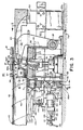
- FIG. 1 is a plan view of the present invention as implemented on a spiral pipe producing machine.
- FIG. 2 is a side elevational view of a spiral pipe producing machine to be used with the preferred embodiment of the present invention.
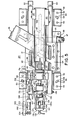
- FIG. 3 shows the preferred embodiment of the present invention and part of the spiral pipe producing machine in elevation and section.
- FIG. 4 is a perspective view of the preferred embodiment of the present invention.
- FIG. 5 is a plan view of the preferred embodiment of the present invention.
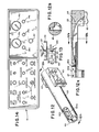
- FIG. 6 is a sectional view taken along lines 6-6 of FIG. 3.
- FIG. 7 is a sectional view taken along lines 7-7 of FIG. 3.
- FIG. 8 is a sectional view taken along lines 8-8 of FIG. 3.
- FIG. 9 is a sectional view taken along lines 9-9 of FIG. 8.
- FIG. 10 is an exploded view of the lower knife guide assembly.
- FIG. 11 is a sectional view of the cutting action of the upper and lower knife blades.
- FIG. 12 is a perspective view of the boom which holds the upper cutting blade.
- FIG. 12a is a sectional view taken along
lines 12a-12a of FIG. 12. - FIG. 12b is a sectional view taken along
lines 12b-12b of FIG. 12a. - FIG. 13 is a front elevational view of the wiper assembly used with the preferred embodiment of the present invention.
- FIG. 14 is plan view of the control panel of a spiral pipe producing machine incorporating the present invention.
- FIG. 15 is a schematic diagram of the pneumatic control system of the present invention.
- Referring now to the drawings, FIGS. 1-3 show elements of a spiral
pipe forming machine 10 which is used with theslitter assembly 50 of the present invention. The present invention illustrated and shown herein is implemented with a spiral pipe producing machine of the assignee of this invention. A particular type of such machine is described in my pending, commonly owned U.S. patent application, serial number 569,752, filed January 10, 1985. It should be understood, however, that the present invention is intended to be used with any type of spiral pipe producing machine. - The spiral pipe producing machine shown in FIGS. 1-3 herein will be briefly described. For a more detailed explanation of spiral pipe producing machines, reference should be made to my pending patent application, particularly with respect to Figures 1, 2, 6 and 7, or U.S. Patent No. 3,132,616 (Hale). This patent application and patent are incorporated by reference herein and made a part hereof for their descriptions of spiral pipe producing machines.
- The spiral
pipe producing machine 10 has a - frame 11 which rests on a base lla. Guide slot llb is provided in the base lla to adjust the angular orientation of the machine frame 11 with respect to the forminghead 21 to determine the diameter of thepipe 42 produced by the machine. A scale llc is provided to indicate the angular orientation of the machine. Guide slot lid provides adjustment for thelower drive roller 17. - A
control cabinet 12 is connected the frame 11. A plurality of control knobs, gauges, and dials 14 are located on thecontrol panel 13 for controlling and monitoring the operation of themachine 10 and theslitter assembly 50. The functions of the various control switches will be described in detail below in connection with FIG. 14. - A
roller housing 16 is mounted in the frame 11. The roller housing contains a plurality of rollers which bend the edges of themetal strip 15 in predetermined shapes for forming a lockseam, and which may form corrugation grooves and stiffening ribs in the metal strip. Anupper drive roller 18 and alower drive roller 17 are rotatably mounted within the frame 11 adjacent theroller housing 16. Theupper drive roller 18 pulls themetal strip 15 into the frame 11, through theroller housing 16, and over thelower drive roller 17. The drive rollers then cooperate to push themetal strip 15 between theupper guide plates 19 and thelower guide plates 20 into the forminghead 21. - The forming
head 21 curls the metal strip into a cylindrical spiral, whereby the opposing, preformed edges of thestrip 15 mesh. The meshed or mated edges are then compressed between asupport roller 32 and a clinchingroller 34 to form alockseam 43. Themetal strip 15 is continuously pushed by thedrive rollers head 21 and between the clinchingroller 34 andsupport roller 32, in a spiral manner, so that a hollow,cylindrical metal pipe 42 is continuously produced with aspiral lockseam 43. - The
support roller 32 is mounted on theupper guide plate 19. Asupport arm 22 pushes down on thesupport roller 32 and holds it in place. Thissupport arm 22 has a thinner cross-section than the support arms that have been previously used in the assignee's spiral pipe producing machines. A thinner support arm is preferred because it can fit within the tight confines of theslitter assembly 50. Thesupport arm 22 rotates about aneccentric shaft 25, so that it comes over.the holding arm 33 and then clamps down thesupport roller 32. A lockingpin 28 on the support arm fits within alip 29 attached to the forminghead base 23 when thesupport arm 22 is in its clamping position. Theeccentric shaft 25 also allows thesupport arm 22 to swing clear of the forminghead 21 when the support arm is not in its clamping position. Acontrol lever 26 is used to rotate thesupport arm 22 about itseccentric axis 25, and controls the pressure applied to thesupport roller 32. The lockinglever 27 releases or locks thecontrol lever 26. - The clinching
roller 34 is moved into and out of its clinching position by a conventionalhydraulic cylinder assembly 35, which operates in a known manner. Thecylinder assembly 35, as shown in FIGS. 3 and 6, includes ayoke 36 which holds the clinchingroller 34. The yoke is appended to apiston rod 37, which slides in and out of thecylinder head 38. Thecylinder head 38 is attached to thecylinder barrel 39 bybolts 40. Thehydraulic cylinder assembly 35 provides the pressure on the clinchingroller 34 to close thelockseam 43. - The forming
head 21 is secured to the forminghead base 23 by the key 24 andbolts 24a. The key 24 allows the forming head to be easily removed. Different size forming heads can be used with the same spiralpipe producing machine 10 to produce spiral seamed pipe of various diameters. - The
slitter assembly 50 is preferably mounted to the machine base lla. In some instances, however, it may be easier to mount theslitter assembly 50 on an adapter plate which is fastened to the machine base. - The
slitter assembly 50 includes two pairs ofbase legs 52. Each opposing pair ofbase legs 52 is fixed to aplate 52a withbolts 53. The pair ofbase legs 52 andplate 52a form one solid piece. It is important that opposing base legs are separated by a precise distance and maintain a precise alignment, so that they do not put pressure on the bearing units 58 (described below). Eachbase leg 52 is secured to the machine base lla viabolts 55. Thesebolts 55 are located withinadjustment slots 54. Eachbase leg 52 is provided with oneadjustment slot 54. The fouradjustment slots 54 are at right angles to apivot pin 156. Theadjustment slots 54 allow theslitter assembly 50 to be rotated about thepivot pin 156 to align the slitter assembly. Proper angular alignment is necessary to obtain clean, rectangular cuts of thepipe 42. - A linear-
motion bearing unit 58 andrail 59 conbination is attached to the upper, inner face of eachbase leg 52. The linear-motion bearing unit 58 andrail 59 combination used in the present embodiment of the invention is a Slide Pack FBW Series, sold by THK America, Inc., Elk Grove Village, Illinois. The bearingunit 58 includes a mountingplate 58a which is fastened to thebase leg 52 bybolts 57. Twoball bearing circuits 58b are located on each mounting plate.. Therail 59 mates withball bearing circuits 58 on two juxta posedbase legs 52, and slides across the ball bearings with very little resistance. Alinear guide beam 60 is attached to eachrail 59 withscrews 58c. Thus, the linear guide beams 60 will slide relative to thebase legs 52 with very little friction. - Two vertical connecting
members 63 are fastened to one end of the linear guide beams 60 with threadedbolts 62. The vertical connectingmembers 63 support the back end of a cantileveredboom 65. The generally cylindrical shapedboom 65 is provided with two recessed, flat surfaces to mate with the vertical connectingmembers 63. A plurality ofbolts 64 fasten the vertical connectingmembers 63 to the back end of the boom. Note that one of the vertical connectingmembers 63 is L-shaped to provide more clearance for the upper andlower guide plates - The diameter of the
boom 65 is small enough so that the boom can move laterally through the forminghead 21. It is presently preferred that the boom diameter is small enough so that the boom can pass through a four inch diameter pipe. Theboom 65 can then be used for any larger diameter pipe as well. - It can be seen from FIGS. 3, 5-7, 12a and 12b that the central section of the
boom 65 is carved out to varying depths. This is done to allow theboom 65 to pass over thesupport roller 32, and to provide sufficient clearance for thesupport arm 22 to move into and out of its clamping position with thesupport roller 32. Trade-offs must be made in the amount of clearance provided for the support roller and support arm, and the amount of material left in the boom to keep it rigid. In a present embodiment of the invention theboom 65 is only 1/8 inch thick at its thinnest point. - The front end of the
boom 65 is provided with areceptacle 66. The cavity defined by the receptacle holds theupper knife housing 68. The sides of the receptacle can be pried apart to allow theupper knife housing 68 to slide into the receptacle cavity. Aslit 66b is provided in thereceptacle 66 to facilitate opening the receptacle. Theshoulders 66a of the receptacle are pulled together bybolts 67 to lock theupper knife housing 68 into thereceptacle 66. - A circular,
passive knife blade 69 is rotatably mounted in the upperknife blade housing 68. The terms "passive" or "idle" mean that the blade may move in response to a tangential force against the cutting edge of the blade, as opposed to actively driving the blade with a motor. Theupper knife blade 69 fits within the forminghead 21 and thepipe 42. It is preferred that the circumference of the blade is small enough so that it also may fit within four inch diameter pipe. Theboom 65 andupper blade 69 are positioned inside thepipe 42 so that their axes are parallel to the the axis of the pipe. The circumferential edge of the blade provides the cutting action. The edge should be located adjacent to the inner pipe surface. It is preferred that the blade edge is almost touching the pipe surface. In the present embodiment of the invention 1/16 mm clearance is used. The edge should not actually touch the pipe, so that it scratches the inner pipe surface and dulls the cutting edge. On the other hand, if the cutting edge is too far above the pipe surface, the pipe will bend towards the upper blade during the cutting process, leaving a wrinkled pipe edge. - A second circular,
passive knife blade 70 is positioned outside of the pipe. The blade is rotatably mounted in alower knife housing 71, which is mounted on a lowerknife guide assembly 73. The lowerknife guide assembly 73 and lowerknife guide housing 71 should position thelower knife blade 70 so that its axis is parallel to the pipe axis and the axis of theupper knife blade 69. The circumferential cutting edge of thelower blade 70 should be adjacent to the the circumferential edge of theupper blade 69 in a lateral position. In the preferred embodiment, the cutting edges of the upper and lower blades are separated by .002"-.004" in the lateral direction. Ideally, the lateral clearance between the upper and lower knife blades should be 2-5% of the gauge of themetal strip 15. There should be a little clearance between the knife blades to allow the strip material to move to facilitate cutting. However, if the blades are positioned too far apart laterally, the cut will leave burrs and sharp edges on the pipe edge. On the other hand, if the blades are too close together laterally, additional force is required to cut the pipe. - The
lower blade 70 should be displaced longitudinally from theupper blade 69, so that it is free and clear of thepipe 42 and the cutting edge of theupper blade 69 when no cutting is required. Thelower blade 70 is then raised in a vertical direction to penetrate the pipe and initiate the cutting process (to be explained below). - The lower
knife guide assembly 73 guides the vertical motion of thelower knife blade 70. (See FIGS. 8-10) This assembly includes afirst guide leg 75 which is secured to alinear guide beam 60 withscrews 77. -
Holes 77a are provided in thefirst leg 75 for thescrews 77. Asecond leg 84 is attached to the otherlinear guide beam 60 withmore screws 77 andscrew holes 77a. Anintermediate leg 80 is connected to thesecond leg 84 withbolts 85. These three legs are made of heat treated steel, hardened to 58-60 Rockwell. Both thefirst leg 75 and theintermediate leg 80 have integral v-shapedtongues 81 facing towards each other. Acenter section 78, with v-shapedslots 79, is adapted to slide up and down on the v-shapedtongues 81. Linear v-shaped needle bearing strips 87, sold by IKO Bearings, Arlington Heights, IL, are placed between the v-shapedslots 79 and the v-shapedtongues 81 to allow thecenter section 78 to move with little frictional resistance. A retaining lip is attached to the top and bottom of the v-shapedslots 79 to keep the bearing strips 87 in place. Four hex screws 88 are threaded into holes in thesecond leg 84. The ends of thesescrews 88 engage the surface of theintermediate leg 80 to apply pressure on the bearing strips 87 between thecenter section 78 and its twoadjacent legs bar 135, which maintains a precise distance between the linear guide beams 60, also puts force on the bearing strips 87. The pressure on the bearing strips 87 should be adjusted with the hex screws 88, so that there is no play in thelower cutting blade 70, either up-and-down or side-to-side. Play in the cutting blade will leave burrs and/or bad cuts. The bottom ends of thefirst leg 75 and thesecond leg 84 are tied together with astrut 90 andbolts 91. - The
lower knife housing 71 is placed in acircular cavity 93 in thecenter section 78 of the lowerknife guide assembly 73. Thelower knife 70 has anintegral shaft 96 which is positioned along the central axis of thecavity 93 of thehousing 71. Theblade shaft 96 is held in position by a plurality of inner bearing races 98,conical bearings 99, and outer bearing races 97. The conical bearings allow theblade 70 to freely rotate when a tangential force is applied to the circumference of theblade 70. Seeger security rings 100 provide support for theouter races 97. The voids between the conical bearings and their races are filled with grease.Seals 101 are provided at the front and back ends of the housing cavity to keep out dirt and dust. Anut 105, which is threaded on the rear of theblade shaft 96, is turned to adjust the pressure on thebearings 99. Theblade 70 should be allowed to freely rotate without any play. Alockwasher 104 is provided to prevent thenut 105 from loosening. Afiller ring 103 matches the inner diameter of theback seal 101 and provides support for the backinner races 98. - As shown best in FIG. 9, the circular face of the
lower knife blade 70 is machined so that its circumferential edge is slightly angled. The circumferential edge should be sharp since it provides the cutting action. Thebores 106 in the axial ends of thecutting blade 70 are used to hold the blade while it is being ground, so that theblade shaft 96 and the cutting edge of the blade are perfectly perpendicular and straight. This is done so that the blade does not wobble. Wrench holes 107 are provided in the face of theblade 70 to hold the blade steady while thenut 105 is tightened. - The
lower knife housing 71 is eccentrically shaped, as best shown in FIG. 8. Theknife housing 71 is rotated in thecavity 93 in thecenter section 78 to adjust the vertical distance between the cutting edge of thelower knife blade 70 and the top of thecenter section 78. Thelower knife housing 71 may also be slid laterally within thecavity 93 to adjust the lateral distance between the cutting edges of theknife blades lower knife housing 71 in position. The bolts 111 are threaded through theholes 112 in thecenter section 78 and engage theannular recess 110 in thelower knife housing 71. - The
upper knife housing 68 andupper knife blade 69 are identical to thelower knife housing 71 andlower knife blade 70. These parts are intended to be interchangeable. The upperknife blade housing 68 is positioned in thereceptacle 66 on the front end of theboom 65. Theeccentric knife housing 68 is rotated within the receptacle to adjust the vertical distance between the cutting edge of theupper knife blade 69 and the bottom of theboom 65. Thus, the distance between the edge of the blade and the inner pipe surface is controlled by theeccentric housing 68. Moreover, the lateral distance between the cutting edges of theknife blades upper knife housing 68 laterally within thereceptacle 70. Theupper knife housing 68 is locked into its desired angular and lateral positions by tighteningbolts 67 to pull theshoulders 66a together. (Theannular recess 110 is not used for the upper knife blade assembly.) - The
center section 78 of the lowerknife guide assembly 73, and hence thelower cutting blade 70, are moved vertically with the pneumatictoggle cylinder assembly 115. The present embodiment of the invention uses a two inch diameter, one inch stroke pneumatic cylinder sold by Milwaukee Cylinder Co. This toggle cylinder assembly includes twotoggle links 118a,b which are pivotally joined by acentral rod 119. Thelower toggle link 118a is also pivotally joined to aprojection 120, which is integral with thestrut 90, via alower rod 121. Theupper link 118b is also pivotally connected to the centerknife holder section 78 via anupper rod 122. Ayoke 117 is connected to thecentral rod 119, which joins the two toggle links 118. Theyoke 117 is appended to apiston rod 116 which slides in and out of thecylinder barrel 123. Arear yoke 124 is connected to the back end of thecylinder barrel 123. Thecylinder barrel 123 is supported by abar 125 which passes through therear yoke 124 andslots 126 in twobrackets 127. Thebrackets 127 are attached to theouter guide legs knife guide assembly 73 atscrew holes 127a (see FIG. 10). Thus, thetoggle cylinder assembly 115 is adapted to move in unison with the linear guide beams 60 via the lowerknife guide assembly 73. - The
toggle cylinder assembly 115 operates under pneumatic pressure to move thelower knife blade 70 from its standby position to its cutting position. When thepiston rod 116 is fully retracted, the uppermost edge of thelower knife blade 70 should be below the lowermost surface of the forminghead 21. (See FIG. 3) The forminghead 21 then can be slid in and out of the forminghead base 23, so that the forming head may be changed. Thelower knife blade 70 should be in its cutting position when thepiston 116 is at the end of its stroke. Thetoggle links 118a,b then should be locked in vertical alignment. This vertical alignment makes it difficult for the cutting force on thelower knife blade 70 to push down the centerknife holder section 78, thereby facilitating cutting of the lockseam, which comprises four layers of themetal strip 15. - When the
toggle cylinder assembly 115 moves thelower knife blade 70 into cutting position, the circumferential edge of thelower knife blade 70 should puncture the pipe surface and overlap with the circumferential edge of theupper knife blade 69 by approximately 1/32 of an inch (See FIG. 11). The amount of overlap may have to be increased so that the blades do not jump over the lockseam. However, if the blades overlap too much, the edge of the cut pipe may wrinkle. - The
toggle cylinder assembly 115 should be adjusted to provide the proper degree of blade overlap for cutting when thepiston rod 116 is at full stroke and thelinks 118a,b are vertically aligned. This adjustment may be made with theadjustment lever 130. This lever has an integral threadedshaft 128 andring 128a. Thebar 125 passes through thering 128a. The threadedshaft 128 passes through anut 129 and anendpiece 131. Theadjustment lever 130 is rotated to move thetoggle cylinder assembly 115 in a horizontal direction along theadjustment slots 126 in thesupport brackets 127. The standby position and the cutting position of theupper toggle link 118b will vary in the vertical direction as the position of thecylinder barrel 123 is varied in the horizontal direction. The vertical standby and cutting positions of thelower knife blade 70 will vary accordingly. If the proper cutting position of thelower knife blade 70 can be achieved with thepiston rod 116 at its end of stroke, operator adjustment (and mistakes) of cutting tolerances can be eliminated. Varying the gauge of themetal strip 15 usually will not require a new adjustment of the cylinder barrel position. - An
air cylinder assembly 148 is provided to assist lateral movement of the upper andlower knife blades cylinder barrel 150 is attached at its back end to astrut 153 by a nut andbolt arrangement 154. Thestrut 153 is attached to abase leg 52 by two bolts. Thepiston rod 149 is connected to asupport bracket 127 of thetoggle cylinder assembly 115 with aclevis 151 and nut andbolt 152. Theair cylinder assembly 148 operates to pull and push thebracket 127. Since thebracket 127 is connected to the linear guide beams 60 via the outer legs of the lowerknife guide assembly 73, theair cylinder assembly 148 also pulls and pushes the linear guide beams 60 and everything connected thereto, including the upper andlower knife blades - The
air cylinder assembly 148 provides friction compression for thelinear bearing units 58. Theslitter assembly 50 weighs too much to be moved solely by the force of the movingstrip 15 after the upper andlower knife blades pipe 42. Theair cylinder assembly 148 facilitates free movement of the cutting blades, and parts connected thereto, so that thepipe 42 will rotate through thecutting blades - A
wiper assembly 136 is provided to wipe lubricant off the pipe 42 (See FIGS. 3, 5, and 13). Arubber wiper blade 137 is attached to awiper holder 138, which is positioned within abasin 139. Lubricant which is collected in thebasin 139 runs off to drain via a hose (not shown) connected to thetube 140. Thebasin 139 is mounted on avertical support member 142. Thesupport member 142 is attached to the free end of acantilevered beam 144. The other end of thebeam 144 is attached to the end of alinear guide beam 60. Thus, thewiper assembly 136 moves with the linear guide beams 60. The free end of the cantilevered beam has threeguide pins 145 in vertical alignment. Thevertical support member 142 has a vertical slot which fits around the three guide pins 145. Thevertical support member 142 andbasin 139 can slide up and down over the guide pins 145, and the guide pins will keep thesupport member 142 andbasin 139 in a vertical orientation. Ahandle 146 is threaded onto the central guide pin so that it can be turned to lock thevertical support member 142 against thebeam 144 to maintain a constant height. - An advantage of this
wiper assembly 136 is that thewiper blade 137 is positioned underneath thepipe 42. Thus, the wiper can wipe lubricant off any diameter pipe from the same position. Moreover, the wiper works with gravity to remove lubricant from the pipe. - The operation of the slitter assembly shown and described above will now be explained, with particular reference to FIGS. 14 and 15. With a few minor exceptions, the dials and switches 14 on the left-hand side of the
control panel 13 perform the same functions they have performed in the assignee's spiral pipe producing machines which have been on the market for over one year. First, the cutter start and stop buttons have been replaced with slitter start and stop buttons. These buttons can be used to trim the leading edge of thepipe 42 using theslitter assembly 50. The LOW dial still controls the pipe speed during the slow down phase and cutting operation, although the cutting speed is not as dependent on strip thickness and pipe diameter. Second, the low speed override switch is no longer used. - The right-hand side of the control panel has been changed in light of the
slitter assembly 50. Thehydraulic gauge 14a is controlled by the dial 14f. When the dial 14f is at a first setting, thehydraulic gauge 14a will indicate the hydraulic pressure on theupper drive roller 18. In a second dial setting, thehydraulic gauge 14a displays the clinchingroller 34 pressure. In a third setting the drive motor pressure is read, and in a fourth position the pump pressure is displayed. The drive rollerhydraulic relief valve 14c controls the drive roller pressure, and the clinching rollerhydraulic relief valve 14d controls the clinching roller pressure. - The
pneumatic pressure gauge 14b displays the pressure on the friction compensatingcylinder assembly 148. Thepneumatic relief valve 14e adjusts the pneumatic pressure on the return stroke of thepiston rod 149. (i.e., during the cutting process). - The schematic diagram for the pneumatic control system of the
slitter assembly 50, shown in FIG. 15, contains several conventional items which perform in a known manner. For example, the source ofair 158 is connected through afilter 159, apressure regulator 160, and alubricator 161.Directional valves 162 control the operation of thetoggle link cylinder 115, thefriction compensating cylinder 148, and apipe discharge cylinder 163. - Spiral seamed pipe is made with the
pipe producing machine 10 in a known manner. Themetal strip 15 can be fed into themachine 10 and formed into spiral seamed pipe in the manner set forth in my above- identified patent application (see pages 18-20). Once the metal strip has been inserted into the machine, the operator starts the mainmotor (oil pump) by pushing the MAIN button. Next, the LUBRICANT button is pushed to start the lubrication pump. The LOW speed selector is adjusted to set the cutting speed, and the HIGH speed selector is set to adjust the pipe production speed. The operator then selects either manual or automatic operation using the AUTO control knob. When the operator hits the HIGH in the automatic mode, thepipe producing machine 10 will continuously make pipe, and theslitter 50 will continuously cut it into sections. In manual mode thepipe producing machine 10 will continuously make the pipe, and the slitter will automatically cut the pipe into a section, but the pipe producing machine will turn off after the pipe section has been. discharged. The present embodiment of the invention runs under a conventional programmable controller. Of course, switches and delay timers could be used instead. - Referring now to FIG. 15, as the
metal strip 15 is formed into spiral seamedpipe 42, thepipe 42 spirally rotates and moves forward laterally. When theouter edge 166 of the pipe hits afirst limit switch 167, theupper drive roller 18 slows down. Hence, thepipe 42 moves more slowly. When thepipe 42 next hits thesecond limit switch 168, the pipe producing machine turns the upper drive roller off, and thepipe 42 stops moving. Air is then supplied to thetoggle link cylinder 115 to raise thelower knife blade 70. The lower knife blade is raised until its circumferential edge overlaps the circumferential edge of the upper knife blade and punctures thepipe 42. Restricted orifices andcheck valves 169 are provided on the inlet and outlet lines of thetoggle cylinder assembly 115, so the lowerknife guide assembly 73 does not rise or fall too fast. - After a 1-2 second delay, the
upper drive roller 18 starts again on slow speed, and thefriction compensating cylinder 148 reverses direction. Thus, thepipe 42 starts moving forward and spirally rotating again. However, thepipe 42 will rotate between the overlapping upper andlower knife blades knife blades knife blades boom 65, the lowerknife guide assembly 73, the linear guide beams 60, and the toggle link cylinder assembly 115) will move in the direction of the pipe, due to the moving pipe pushing on the cutting blades and the pulling action of the frictioncompensation cylinder assembly 115. After one full rotation of thepipe 42, the pipe should be completely cut rectangularly (i.e., perpendicular to the axis of the pipe) by the upper and lower knife blades. - The friction compensating
air cylinder 115 operates under low pressure on its return ("pull") stroke. This pressure is controlled by apressure relief valve 170, which is adjusted using thepneumatic control knob 14e on thecontrol panel 13. The dashedline 170a represents the relief line. The pulling pressure must be adjusted to compensate for any frictional resistance in thelinear bearing units 58. The pressure in thecylinder 115 should balance the friction in the bearings so that thecutting blades boom 65, or automatically with valves. Thepressure compensating cylinder 115 allows the cutting blades and attached components to move with the pipe, as if there were no frictional resistance to such movement so that the cutting blades were moving only under the force of the moving pipe. - In order to achieve a clean, rectangular cut of the pipe, it is important that the
cutting blades - High pressure is used to return ("push") the
pressure compensating cylinder 115 back to its starting position, since the extension stroke ofpiston rod 149 is not as sensitive. Apressure relief valve 171 is used to adjust this pressure. Therelief valve 171 andpressure gauge 171a are located inside thecontrol cabinet 12. A check valve and restrictedorifice 169 are used to dampen the high pressure return. - The
slitter assembly 50 continues to move with the pipe until the slitter assembly contacts athird limit switch 173. This limit switch is placed at a position at which any size (diameter) pipe made with thepipe producing machine 10 andslitter assembly 50 would complete one rotation, so that the cut will be complete. Thelimit switch 173 should actually provide for a little overlap in the cut. If the cut is not quite complete, two sections of pipe will be attached by a sliver of metal. Pipe ranging from 4 inch to 24 inch diameters will complete one rotation in approximately 5-1/2 inches of lateral movement. - The
pipe producing machine 10 then stops again. Thetoggle cylinder 115 is lowered to the standby position. After a short time delay thefriction compensating cylinder 148 reverses direction, and returns thecutting blades - Next, the
pipe discharge cylinder 163 raises arms 175 to discharge the cut section of pipe onto a run-off table. Check valves and restrictedorifices 169 are provided so that the discharge arms 175 are raised and lowered slowly and gently. When the discharge arms 175 return they will close afourth limit switch 176. Thepipe producing machine 10 will not start again until this limit switch has been closed. - If the
pipe producing machine 10 is in automatic mode and thefourth limit switch 176 closes, themachine 10 andslitter 50 will automatically repeat the above process for forming and slitting pipe. If in manual mode, the operator must hit the HIGH button to repeat the above process for one more section of pipe. - It follows from the foregoing description that the present invention provides several advantages over high speed saw blades for cutting hollow metal pipe. The cutting blades of the present invention use a shearing action, like scissors, to cut the pipe. The pipe is cut without the sparks, noise and danger of a high-speed saw blade. Thus, the present invention provides a safer environment for manufacturing spiral seamed pipes. Further, the cutting process of the present invention does not leave burrs on the ends of the cut pipe sections. This increases the efficiency of the pipe forming process because manpower does not have to be utilized to de-burr the cut pipes. Still further, the cutting apparatus of the present invention may be easily adapted to existing spiral pipe producing machines.
- It should be understood that various changes and modifications to the preferred embodiment described above will be apparent to those skilled in the art. For example, the preferred embodiment of the invention uses idle, rotatable knife blades. It is possible that the same type of knife blades could be driven with a motor, although that would defeat some of the advantages of the invention.
- It is intended that the foregoing description be regarded as illustrative rather than limiting, and that it be understood that it is the following claims, including all equivalents, which are intended to define the scope of the invention.
Claims (10)
Priority Applications (1)
| Application Number | Priority Date | Filing Date | Title |
|---|---|---|---|
| AT86108191T ATE72531T1 (en) | 1985-06-18 | 1986-06-16 | PIPE CUTTING DEVICE. |
Applications Claiming Priority (2)
| Application Number | Priority Date | Filing Date | Title |
|---|---|---|---|
| US74623785A | 1985-06-18 | 1985-06-18 | |
| US746237 | 1985-06-18 |
Publications (3)
| Publication Number | Publication Date |
|---|---|
| EP0206201A2 true EP0206201A2 (en) | 1986-12-30 |
| EP0206201A3 EP0206201A3 (en) | 1989-06-07 |
| EP0206201B1 EP0206201B1 (en) | 1992-02-12 |
Family
ID=24999992
Family Applications (1)
| Application Number | Title | Priority Date | Filing Date |
|---|---|---|---|
| EP86108191A Expired - Lifetime EP0206201B1 (en) | 1985-06-18 | 1986-06-16 | Apparatus for cutting hollow pipes |
Country Status (8)
| Country | Link |
|---|---|
| US (1) | US4706481A (en) |
| EP (1) | EP0206201B1 (en) |
| JP (1) | JPH0673768B2 (en) |
| AT (1) | ATE72531T1 (en) |
| AU (1) | AU580173B2 (en) |
| CA (1) | CA1262616A (en) |
| DE (1) | DE3683872D1 (en) |
| FI (1) | FI83936C (en) |
Cited By (5)
| Publication number | Priority date | Publication date | Assignee | Title |
|---|---|---|---|---|
| EP0403425A1 (en) * | 1989-06-13 | 1990-12-19 | Emil Suter Maschinenfabrik AG | Method and apparatus for cutting tubes |
| WO1993017803A1 (en) * | 1992-03-06 | 1993-09-16 | Bubb, Antony, John, Allen | Apparatus for cutting helically wound metal tubing |
| WO1998017412A1 (en) * | 1996-10-21 | 1998-04-30 | Filterwerk Mann+Hummel Gmbh | Arrangement for shaping a helical pipe |
| WO2010098719A1 (en) * | 2009-02-27 | 2010-09-02 | Spiro International S.A. | Tube cutting |
| CN102126045A (en) * | 2010-12-16 | 2011-07-20 | 济南玛钢钢管制造有限公司 | Automatic blanking machine for steel pipes |
Families Citing this family (35)
| Publication number | Priority date | Publication date | Assignee | Title |
|---|---|---|---|---|
| FR2589384B1 (en) * | 1985-10-30 | 1988-01-22 | Lhomme Sa | DEVICE FOR CUTTING TUBES |
| US4823579A (en) * | 1987-12-02 | 1989-04-25 | Spiro America Inc. | Apparatus for cutting hollow pipes |
| US5105639A (en) * | 1989-02-23 | 1992-04-21 | Spiro America Inc. | Apparatus for forming spiral pipe |
| US4924684A (en) * | 1989-02-23 | 1990-05-15 | Spiro America Inc. | Apparatus for forming and cutting spiral pipe |
| US5193374A (en) * | 1991-02-20 | 1993-03-16 | Spiro America Inc. | Apparatus for cutting spiral pipe |
| US5257521A (en) * | 1992-06-17 | 1993-11-02 | Spiro America, Inc. | Apparatus and method for cutting spiral pipe |
| EP0714713B1 (en) | 1994-11-30 | 2000-05-10 | Lindab Aktiebolag | Apparatus for cutting spiral pipe |
| CN1080605C (en) * | 1995-01-20 | 2002-03-13 | 林登公司 | Method and appts. for producing helically-wound lock-seam tubing with reduced lubrication |
| US5606884A (en) * | 1995-06-30 | 1997-03-04 | Lindab Ab | Method and apparatus for producing helically-wound lock-seam tubing with reduced lubrication |
| USD379358S (en) * | 1995-03-08 | 1997-05-20 | Protol A.G. | Clinching roller |
| SE507901C2 (en) * | 1995-03-08 | 1998-07-27 | Protol Ag | Method and apparatus for making spiral-folded tubes, and such spiral-folded tubes |
| US6003220A (en) * | 1995-03-08 | 1999-12-21 | Protol A. G. | Method and apparatus for producing helically wound lock-seam tubing |
| US5609055A (en) * | 1995-03-20 | 1997-03-11 | Spiral-Helix, Inc. | Method and apparatus for cutting and notching a hollow pipe |
| US5636541A (en) * | 1995-06-23 | 1997-06-10 | Lindab Ab | Apparatus for forming and cutting spiral pipe |
| JP2001527467A (en) * | 1995-06-30 | 2001-12-25 | リンダブ、アクチボラグ | Method and apparatus for manufacturing helical wound rock seam tubes using a small amount of lubricant |
| US5860305A (en) * | 1997-04-15 | 1999-01-19 | Lindab Ab | Pipe cutter with dual outer cutting knives and method |
| US5992275A (en) * | 1997-12-05 | 1999-11-30 | Lindab Ab | Pipe cutter having non-rotating, overlapping knives |
| US6000260A (en) * | 1998-04-06 | 1999-12-14 | Miller S. Price | Spiral duct ovalizer |
| US6192726B1 (en) | 1999-11-05 | 2001-02-27 | Lindab Ab | System and method for corrugating spiral formed pipe |
| US6295853B1 (en) | 2000-02-18 | 2001-10-02 | Lindab Ab | Spirally formed pipe cutter with driving mechanism to actively rotate inner knife |
| KR20020072997A (en) * | 2001-03-14 | 2002-09-19 | 주식회사 보람테크 | cutting device of machine for forming steel pipe |
| CH695883A5 (en) * | 2002-10-14 | 2006-10-13 | Spiro Sa | Quick clamping device. |
| US6874398B2 (en) | 2002-10-18 | 2005-04-05 | Spiro Sa | Assembly for cutting a tube |
| US7137281B1 (en) * | 2004-02-23 | 2006-11-21 | Mccorvey Robert L | Process and apparatus for forming oversized circular pipe |
| PL1945386T3 (en) | 2005-09-20 | 2017-07-31 | Helix International, Inc | Machine and method to produce expanded metal spirally lock-seamed tubing from solid coil stock |
| US8091455B2 (en) | 2008-01-30 | 2012-01-10 | Cummins Filtration Ip, Inc. | Apparatus, system, and method for cutting tubes |
| WO2014132455A1 (en) * | 2013-02-28 | 2014-09-04 | 株式会社 昭和螺旋管製作所 | Interlock tube manufacturing method and manufacturing device therefor |
| US9782812B2 (en) * | 2014-03-26 | 2017-10-10 | Roderick Clarence Minch | Method and apparatus for cutting openings in sidewall of spiral pipe |
| CN104259243B (en) * | 2014-09-01 | 2016-11-09 | 黄伟明 | Tubing mechanized production system |
| CN104226724B (en) * | 2014-09-01 | 2017-07-04 | 黄伟明 | A kind of tubing full-automation production system |
| CN105108226B (en) * | 2015-10-14 | 2017-09-12 | 江苏江扬建材机械有限公司 | A kind of plate shearing machine and the spiral weld-pipe mill comprising the plate shearing machine |
| KR102632086B1 (en) | 2017-01-12 | 2024-01-31 | 키스톤 타워 시스템스, 인코포레이티드 | Cylindrical tube formation |
| IT201800001909A1 (en) * | 2018-01-25 | 2019-07-25 | Cml Int S P A | Set of machine for bending an elongated piece and relative support bench |
| CN110142819B (en) * | 2019-06-12 | 2023-05-16 | 德科摩橡塑科技(东莞)有限公司 | Bellows cutting device |
| CN117798989B (en) * | 2024-02-29 | 2024-05-03 | 常州市晋纯环保科技有限公司 | Integrated slitting and conveying workbench applied to air filter element |
Citations (4)
| Publication number | Priority date | Publication date | Assignee | Title |
|---|---|---|---|---|
| US3132616A (en) * | 1961-02-02 | 1964-05-12 | Bentworth Engineers N V | Spiral pipe producing apparatus |
| FR1599934A (en) * | 1968-01-29 | 1970-07-20 | ||
| FR2307605A1 (en) * | 1975-04-17 | 1976-11-12 | Pont A Mousson | Flying cutters for spirally welded pipe mfr. - has serrated cutter wheels hydraulically clamped at each and operated by scissors action |
| US4567742A (en) * | 1984-01-10 | 1986-02-04 | Spiro America Inc. | Ribbed spiral pipe producing machine |
Family Cites Families (14)
| Publication number | Priority date | Publication date | Assignee | Title |
|---|---|---|---|---|
| US684539A (en) * | 1898-09-27 | 1901-10-15 | Union Paper Company | Cut-off mechanism for paper-tube machines, &c. |
| US694524A (en) * | 1901-03-22 | 1902-03-04 | Nat Tube Co | Rotary pipe-cutting machine. |
| US957966A (en) * | 1908-07-10 | 1910-05-17 | Single Service Package Corp Am | Machine for forming and cutting off tubes. |
| US1345458A (en) * | 1917-03-30 | 1920-07-06 | American Vulcanized Fibre Co | Device for cutting tubes |
| GB830504A (en) * | 1955-12-20 | 1960-03-16 | Spiro Internat A S | Improvements in machines for producing tubing from continuous strip material |
| SU473572A1 (en) * | 1973-01-18 | 1975-06-14 | Барнаульский аппаратурно-механический завод | Pipe cutting machine |
| NL7313574A (en) * | 1973-10-03 | 1975-04-07 | Philips Nv | DEVICE FOR CUTTING RINGS FROM A HOLLOW, NECK AND LONG CYLINDRICAL OBJECT. |
| US3982414A (en) * | 1973-10-26 | 1976-09-28 | Manufacturers Systems, Inc. | Machine for making corrugated flexible cylindrical duct |
| SU531592A1 (en) * | 1974-10-04 | 1976-10-15 | Азовское Специальное Конструкторское Бюро Кузнечно-Прессовых Автоматов И Гибочных Машин | The device for the brand |
| FR2311625A1 (en) * | 1975-05-23 | 1976-12-17 | Roulements Soc Nouvelle | Cutting off tubes into sections - using hydraulic cylinder to bring together knife edge rollers inside and outside tube to cut by shearing |
| US4054069A (en) * | 1976-11-19 | 1977-10-18 | Bazil H. Sugden | Elbow-making machine |
| JPS5380881A (en) * | 1976-12-27 | 1978-07-17 | Komatsu Ltd | Metallic conduit cutter |
| US4244202A (en) * | 1978-10-20 | 1981-01-13 | Manufacture Systems, Inc. | Apparatus for making corrugated flexible metal tubing |
| JPS5930624Y2 (en) * | 1983-05-06 | 1984-08-31 | 株式会社日立製作所 | Gate pulse generation circuit |
-
1986
- 1986-06-16 AT AT86108191T patent/ATE72531T1/en not_active IP Right Cessation
- 1986-06-16 EP EP86108191A patent/EP0206201B1/en not_active Expired - Lifetime
- 1986-06-16 CA CA000511698A patent/CA1262616A/en not_active Expired
- 1986-06-16 DE DE8686108191T patent/DE3683872D1/en not_active Expired - Lifetime
- 1986-06-17 AU AU58900/86A patent/AU580173B2/en not_active Expired
- 1986-06-17 US US06/876,286 patent/US4706481A/en not_active Expired - Lifetime
- 1986-06-17 FI FI862589A patent/FI83936C/en not_active IP Right Cessation
- 1986-06-18 JP JP61142446A patent/JPH0673768B2/en not_active Expired - Lifetime
Patent Citations (4)
| Publication number | Priority date | Publication date | Assignee | Title |
|---|---|---|---|---|
| US3132616A (en) * | 1961-02-02 | 1964-05-12 | Bentworth Engineers N V | Spiral pipe producing apparatus |
| FR1599934A (en) * | 1968-01-29 | 1970-07-20 | ||
| FR2307605A1 (en) * | 1975-04-17 | 1976-11-12 | Pont A Mousson | Flying cutters for spirally welded pipe mfr. - has serrated cutter wheels hydraulically clamped at each and operated by scissors action |
| US4567742A (en) * | 1984-01-10 | 1986-02-04 | Spiro America Inc. | Ribbed spiral pipe producing machine |
Cited By (10)
| Publication number | Priority date | Publication date | Assignee | Title |
|---|---|---|---|---|
| EP0403425A1 (en) * | 1989-06-13 | 1990-12-19 | Emil Suter Maschinenfabrik AG | Method and apparatus for cutting tubes |
| US5074018A (en) * | 1989-06-13 | 1991-12-24 | Emil Suter Maschinenfabrik Ag | Method and device for the cutting of pipes into separate pipe sections |
| WO1993017803A1 (en) * | 1992-03-06 | 1993-09-16 | Bubb, Antony, John, Allen | Apparatus for cutting helically wound metal tubing |
| GB2273254A (en) * | 1992-03-06 | 1994-06-15 | Bubb Anthony John Allen | Apparatus for cutting helically wound metal tubing |
| GB2273254B (en) * | 1992-03-06 | 1995-01-25 | Bubb Anthony John Allen | Apparatus for cutting helically wound metal tubing |
| US5477717A (en) * | 1992-03-06 | 1995-12-26 | Spiro Machines S.A. | Apparatus for cutting helically wound metal tubing |
| WO1998017412A1 (en) * | 1996-10-21 | 1998-04-30 | Filterwerk Mann+Hummel Gmbh | Arrangement for shaping a helical pipe |
| WO2010098719A1 (en) * | 2009-02-27 | 2010-09-02 | Spiro International S.A. | Tube cutting |
| CN102126045A (en) * | 2010-12-16 | 2011-07-20 | 济南玛钢钢管制造有限公司 | Automatic blanking machine for steel pipes |
| CN102126045B (en) * | 2010-12-16 | 2012-10-17 | 济南玛钢钢管制造有限公司 | Automatic blanking machine for steel pipes |
Also Published As
| Publication number | Publication date |
|---|---|
| JPS6254619A (en) | 1987-03-10 |
| FI83936C (en) | 1991-09-25 |
| AU5890086A (en) | 1986-12-24 |
| CA1262616A (en) | 1989-11-07 |
| EP0206201A3 (en) | 1989-06-07 |
| US4706481A (en) | 1987-11-17 |
| FI83936B (en) | 1991-06-14 |
| EP0206201B1 (en) | 1992-02-12 |
| JPH0673768B2 (en) | 1994-09-21 |
| DE3683872D1 (en) | 1992-03-26 |
| AU580173B2 (en) | 1989-01-05 |
| FI862589A (en) | 1986-12-19 |
| FI862589A0 (en) | 1986-06-17 |
| ATE72531T1 (en) | 1992-02-15 |
Similar Documents
| Publication | Publication Date | Title |
|---|---|---|
| EP0206201B1 (en) | Apparatus for cutting hollow pipes | |
| EP1693173A1 (en) | Controllable wall sawing machine and control method | |
| US4454794A (en) | Truss web saw | |
| EP1035929B1 (en) | Method of cutting a spirally formed pipe by using non-rotating, overlapping knives | |
| US6352012B1 (en) | Supported shear with reversible linear drive and in-feed table therefor | |
| US5609055A (en) | Method and apparatus for cutting and notching a hollow pipe | |
| US4823579A (en) | Apparatus for cutting hollow pipes | |
| DE3416664C2 (en) | Device for controlling the cutting speed of the saw blade of a band saw machine | |
| DE4236347C2 (en) | Rip cutter | |
| EP0264806B1 (en) | Apparatus for crimping pipe | |
| DE69314118T2 (en) | DEVICE FOR CUTTING SCREW-SHAPED METAL TUBES | |
| DE2701788B2 (en) | Device for the separation of continuously advancing strand-shaped material | |
| US5860305A (en) | Pipe cutter with dual outer cutting knives and method | |
| JPH0911022A (en) | Molding and cutting device for spiral pipe | |
| US5030472A (en) | Spirally sliced boneless meat product | |
| US4821635A (en) | Meat slicing apparatus | |
| EP0714713B1 (en) | Apparatus for cutting spiral pipe | |
| CN2220912Y (en) | Portable pipe cutter | |
| CN220446617U (en) | Shearing equipment is used in spool paper production | |
| CA1043248A (en) | Rake angle control for a shear or the like | |
| KR100727106B1 (en) | Edge cutting apparatus of running strip | |
| EP0463274B1 (en) | Roll grooving apparatus | |
| JPS5822620A (en) | Apparatus for forming rough teeth |
Legal Events
| Date | Code | Title | Description |
|---|---|---|---|
| PUAI | Public reference made under article 153(3) epc to a published international application that has entered the european phase |
Free format text: ORIGINAL CODE: 0009012 |
|
| AK | Designated contracting states |
Kind code of ref document: A2 Designated state(s): AT CH DE FR GB IT LI NL SE |
|
| PUAL | Search report despatched |
Free format text: ORIGINAL CODE: 0009013 |
|
| AK | Designated contracting states |
Kind code of ref document: A3 Designated state(s): AT CH DE FR GB IT LI NL SE |
|
| 17P | Request for examination filed |
Effective date: 19891128 |
|
| 17Q | First examination report despatched |
Effective date: 19901227 |
|
| ITF | It: translation for a ep patent filed | ||
| GRAA | (expected) grant |
Free format text: ORIGINAL CODE: 0009210 |
|
| AK | Designated contracting states |
Kind code of ref document: B1 Designated state(s): AT CH DE FR GB IT LI NL SE |
|
| REF | Corresponds to: |
Ref document number: 72531 Country of ref document: AT Date of ref document: 19920215 Kind code of ref document: T |
|
| ET | Fr: translation filed | ||
| REF | Corresponds to: |
Ref document number: 3683872 Country of ref document: DE Date of ref document: 19920326 |
|
| PGFP | Annual fee paid to national office [announced via postgrant information from national office to epo] |
Ref country code: NL Payment date: 19920630 Year of fee payment: 7 |
|
| PLBI | Opposition filed |
Free format text: ORIGINAL CODE: 0009260 |
|
| PLAB | Opposition data, opponent's data or that of the opponent's representative modified |
Free format text: ORIGINAL CODE: 0009299OPPO |
|
| 26 | Opposition filed |
Opponent name: HOEGGER ALPINA AG Effective date: 19921109 |
|
| R26 | Opposition filed (corrected) |
Opponent name: SPIRO MACHINES S.A. Effective date: 19921109 |
|
| NLR1 | Nl: opposition has been filed with the epo |
Opponent name: HOEGGER ALPINA AG |
|
| PG25 | Lapsed in a contracting state [announced via postgrant information from national office to epo] |
Ref country code: NL Effective date: 19940101 |
|
| PLBM | Termination of opposition procedure: date of legal effect published |
Free format text: ORIGINAL CODE: 0009276 |
|
| STAA | Information on the status of an ep patent application or granted ep patent |
Free format text: STATUS: OPPOSITION PROCEDURE CLOSED |
|
| NLV4 | Nl: lapsed or anulled due to non-payment of the annual fee | ||
| 27C | Opposition proceedings terminated |
Effective date: 19931102 |
|
| EAL | Se: european patent in force in sweden |
Ref document number: 86108191.7 |
|
| REG | Reference to a national code |
Ref country code: CH Ref legal event code: PUE Owner name: SPIRO AMERICA INC. TRANSFER- LINDAB AB |
|
| REG | Reference to a national code |
Ref country code: GB Ref legal event code: 732E |
|
| REG | Reference to a national code |
Ref country code: FR Ref legal event code: TP Ref country code: FR Ref legal event code: CD |
|
| REG | Reference to a national code |
Ref country code: GB Ref legal event code: IF02 |
|
| PGFP | Annual fee paid to national office [announced via postgrant information from national office to epo] |
Ref country code: GB Payment date: 20050520 Year of fee payment: 20 |
|
| PGFP | Annual fee paid to national office [announced via postgrant information from national office to epo] |
Ref country code: SE Payment date: 20050602 Year of fee payment: 20 |
|
| PGFP | Annual fee paid to national office [announced via postgrant information from national office to epo] |
Ref country code: DE Payment date: 20050603 Year of fee payment: 20 Ref country code: CH Payment date: 20050603 Year of fee payment: 20 |
|
| PGFP | Annual fee paid to national office [announced via postgrant information from national office to epo] |
Ref country code: AT Payment date: 20050606 Year of fee payment: 20 |
|
| PGFP | Annual fee paid to national office [announced via postgrant information from national office to epo] |
Ref country code: FR Payment date: 20050609 Year of fee payment: 20 |
|
| PGFP | Annual fee paid to national office [announced via postgrant information from national office to epo] |
Ref country code: IT Payment date: 20050624 Year of fee payment: 20 |
|
| PG25 | Lapsed in a contracting state [announced via postgrant information from national office to epo] |
Ref country code: GB Free format text: LAPSE BECAUSE OF EXPIRATION OF PROTECTION Effective date: 20060615 |
|
| REG | Reference to a national code |
Ref country code: GB Ref legal event code: PE20 |
|
| REG | Reference to a national code |
Ref country code: CH Ref legal event code: PL |
|
| EUG | Se: european patent has lapsed |