EP0204880A2 - Plate heat exchanger - Google Patents
Plate heat exchanger Download PDFInfo
- Publication number
- EP0204880A2 EP0204880A2 EP85850370A EP85850370A EP0204880A2 EP 0204880 A2 EP0204880 A2 EP 0204880A2 EP 85850370 A EP85850370 A EP 85850370A EP 85850370 A EP85850370 A EP 85850370A EP 0204880 A2 EP0204880 A2 EP 0204880A2
- Authority
- EP
- European Patent Office
- Prior art keywords
- plate
- heat exchanger
- plates
- ridges
- relative
- Prior art date
- Legal status (The legal status is an assumption and is not a legal conclusion. Google has not performed a legal analysis and makes no representation as to the accuracy of the status listed.)
- Granted
Links
- 238000010438 heat treatment Methods 0.000 claims abstract description 14
- 238000012856 packing Methods 0.000 claims abstract description 9
- 238000004519 manufacturing process Methods 0.000 description 2
- 230000015572 biosynthetic process Effects 0.000 description 1
- 239000002360 explosive Substances 0.000 description 1
- 238000007789 sealing Methods 0.000 description 1
Images

Classifications
-
- F—MECHANICAL ENGINEERING; LIGHTING; HEATING; WEAPONS; BLASTING
- F28—HEAT EXCHANGE IN GENERAL
- F28F—DETAILS OF HEAT-EXCHANGE AND HEAT-TRANSFER APPARATUS, OF GENERAL APPLICATION
- F28F3/00—Plate-like or laminated elements; Assemblies of plate-like or laminated elements
- F28F3/08—Elements constructed for building-up into stacks, e.g. capable of being taken apart for cleaning
- F28F3/083—Elements constructed for building-up into stacks, e.g. capable of being taken apart for cleaning capable of being taken apart
-
- F—MECHANICAL ENGINEERING; LIGHTING; HEATING; WEAPONS; BLASTING
- F28—HEAT EXCHANGE IN GENERAL
- F28D—HEAT-EXCHANGE APPARATUS, NOT PROVIDED FOR IN ANOTHER SUBCLASS, IN WHICH THE HEAT-EXCHANGE MEDIA DO NOT COME INTO DIRECT CONTACT
- F28D9/00—Heat-exchange apparatus having stationary plate-like or laminated conduit assemblies for both heat-exchange media, the media being in contact with different sides of a conduit wall
- F28D9/0031—Heat-exchange apparatus having stationary plate-like or laminated conduit assemblies for both heat-exchange media, the media being in contact with different sides of a conduit wall the conduits for one heat-exchange medium being formed by paired plates touching each other
- F28D9/0043—Heat-exchange apparatus having stationary plate-like or laminated conduit assemblies for both heat-exchange media, the media being in contact with different sides of a conduit wall the conduits for one heat-exchange medium being formed by paired plates touching each other the plates having openings therein for circulation of at least one heat-exchange medium from one conduit to another
- F28D9/005—Heat-exchange apparatus having stationary plate-like or laminated conduit assemblies for both heat-exchange media, the media being in contact with different sides of a conduit wall the conduits for one heat-exchange medium being formed by paired plates touching each other the plates having openings therein for circulation of at least one heat-exchange medium from one conduit to another the plates having openings therein for both heat-exchange media
Definitions
- This invention relates to a plate heat exchanger in the form of several heat exchanger plates placed closed to anC sealed against each other, which are provided with pressed-out ridges to form the heating surface of the relative plate.
- Fig. 1 shows schematically a heat exchanger plate according to the invention
- F.ig. 2 a part section taken on line lI-II in Fig. 1
- Figs. 3 and 4 show very schematically two examples of how the ridges of two adjacent heat exchanger plates extend relative to each other
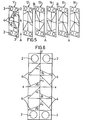
- Fig. 5 shows schematically and in an explosive view the placement of six heat exchanger plates in a plate heat exchanger
- Fig . 6 shows schematically another embodiment of a heat exchanger plate.
- a heat exchanger plate 1 in accordance with the invention is shown.
- the plate 1 is in conventional manner provided with openings or ports 2 and packing grooves 3 for edge packings and packings around two of the ports.
- the heat exchanger plate 1 is further provided with parallel, pressed-out ridges 4 forming the heating surface of the plate. It is understood that not all the ridges are drawn in the figure.
- the heating surface of the heat exchanger plate is divided into four area portions 5-8, the ridges 4 in the area portion 5 intersecting the Y-axis of the plate at an angle a 1 , in the area portion 6 the Y-ax.is at an angle ⁇ 1 , in the area portion 7 the Y-axis at an angle a 2 and in the area portion 8 the Y-axis at an angle ⁇ 2 .
- Fig. 2 shows a part section taken on line II-II in Fig. 1, three adjacent plates being drawn.
- the packing groove 9 has its bottom placed in the central plane of the heat exchanger plate 1, which is known per se. By this location of the packing groove 9 a plate can be turned 180 0 in three different directions relative to an adjacent plate. Thus, the plate can be turned in its own plane, around its longitudinal axis (Y-axis) and its width axis (X-axis). The sealing surfaces of the packing grooves in adjacent plates will be equal in all three cases.
- the plate patterns around the packing grooves are not shown in the figures and it is to be understood that the corrugations in these areas are so formed that the required support points between adjacent plates are obtained at a mutual turning of these.
- Figs. 1, 3 and 4 In order to describe the formation of different plate channels it is referred to Figs. 1, 3 and 4. Assuming that a similar plate is adapted close to a plate according to Fig. 1 and turned 180 about its X-axis. The arrow angles of the pressed-out ridges in the heating surface will then point in a direction contrary to the turned plate as compared with the starting plate according to Fig. 1. Is the plate, on the other hand, turned about its Y-axis, the arrow angles will have the same direction as the arrow angles in the original plate according to Fig. 1.
- a plate is shown as turned about the X-axis, the ridges intersecting each other at an angle (a+6).
- Fig. 4 shows the corresponding thing but with the plate turned 180° about the Y-axis, the angle between the ridges of the plates being (180 + ⁇ - a).
- the angles a and ⁇ should be selected with respect to the desired thermal length of the channel, the demand for a sufficient number of support points being considered. The angle between the intersecting ridges have a considerable influence on the flow properties of the plate channel.
- the plate 11 has the same orientation as the plate shown in Fig. 1.
- the adjacent plate 12 has been turned about its Y-axis.
- the arrow angles of the ridges will point in the same direction between plate 11 and plate 12.
- a flow passage is formed between the plates 11 and 12 for one medium, the medium A.
- the plate 13 is the plate according to Fig. 1 turned 180° in its own plane.
- a flow passage of the other medium, medium B, is then obtained, which passage has oppositely directed arrow angles.
- Plate 14 is a plate 1 turned 180 about the X-axis and the arrow angles between plate 13 and plate 14 will point in the same direction.
- Plate 15 has the same orientation as plate 11.
- the arrow angles of the ridges will be directed in opposite directions between plate 14 and plate 15.
- Plate 16 is turned 180° about its Y-axis and the arrow angles of the ridges point in the same direction as at plate 15.
- the plates 11, 13 and 15 have their sides - heating surfaces - in the same direction and in the example as shown in Fig.1. With respect to this side or heating surface the plates 12, 14 and 16 are turned in the other direction.
- the media will flow via selected ports 2 in every other plate channel, e.g. the medium A will flow in the plate channels formed between the plates 11 and 12, the plates 13 and 14 and the plates 15 and 16..
- the medium B will flow in the space between the plate 12 and 13 and the plates 14 and 15.
- the flow passages of the medium A have the arrow angles of the ridges in the same direction whereas the channels in which the medium B is flowing, have counterdirected arrow angles of the adjacent plates.
- Fig. 5 shows a plate heat exchanger where the medium A flows merely through one sort of flow passages and the medium B merely through another sort of flow passages.
- the plate can of course be designed in several ways within the scope of the invention maintaining only one type of heat exchanger plate with the economical advantages brought by this.
- Fig. 6 a plate having eight different area portions is shown.
- the four upper area portions agree in principle with each other as well as the four lower area portions, in principle the area portions of the plate according to Fig. 1. This means quite practically that the four upper portions are pressed in one step in the manufacture of the plate and in next step the four lower portions.
Landscapes
- Engineering & Computer Science (AREA)
- Physics & Mathematics (AREA)
- Thermal Sciences (AREA)
- Mechanical Engineering (AREA)
- General Engineering & Computer Science (AREA)
- Heat-Exchange Devices With Radiators And Conduit Assemblies (AREA)
Abstract
Description
- This invention relates to a plate heat exchanger in the form of several heat exchanger plates placed closed to anC sealed against each other, which are provided with pressed-out ridges to form the heating surface of the relative plate.
- It is intended by the invention to provide two different flow passages in the same plate heat exchanger, which passages can arbitrarily be selected for both the media flowing in the plate heat exchanger.
- Due to high manufacturing costs of pressing tools for heat exchanger plates and costs of storage of such plates it is neccessary for a manufacturer to restrict the plate assortment. However, at the same time it is desired to provide such a great number of variations or variants of plate channels as possible in a plate heat exchanger so that a heat exchanging task can be solved with the least possible heating surface which desideratum, however, is very difficult to satisfy due to the limited plate assortment.
- Thus, it is possible today to vary the plate channels in the same plate heat exchanger which, however, is done with different types of plates.
- It is possible by the present invention, such as it is apparent from the characterizing portions of the claims, to form two different flow passages using only one type of plate in the plate heat exchanger, the plates being turned in three different ways relative to one another.
- The invention will be described more in detail in the form of examples with reference to the drawing, wherein Fig. 1 shows schematically a heat exchanger plate according to the invention, F.ig. 2 a part section taken on line lI-II in Fig. 1, Figs. 3 and 4 show very schematically two examples of how the ridges of two adjacent heat exchanger plates extend relative to each other, Fig. 5 shows schematically and in an explosive view the placement of six heat exchanger plates in a plate heat exchanger and Fig. 6 shows schematically another embodiment of a heat exchanger plate.
- In Fig. 1 a
heat exchanger plate 1 in accordance with the invention is shown. Theplate 1 is in conventional manner provided with openings orports 2 and packinggrooves 3 for edge packings and packings around two of the ports. Theheat exchanger plate 1 is further provided with parallel, pressed-outridges 4 forming the heating surface of the plate. It is understood that not all the ridges are drawn in the figure. The heating surface of the heat exchanger plate is divided into four area portions 5-8, theridges 4 in thearea portion 5 intersecting the Y-axis of the plate at an angle a1, in thearea portion 6 the Y-ax.is at an angle β1, in thearea portion 7 the Y-axis at an angle a 2 and in thearea portion 8 the Y-axis at an angle β2. - Fig. 2 shows a part section taken on line II-II in Fig. 1, three adjacent plates being drawn. The
packing groove 9 has its bottom placed in the central plane of theheat exchanger plate 1, which is known per se. By this location of the packing groove 9 a plate can be turned 1800 in three different directions relative to an adjacent plate. Thus, the plate can be turned in its own plane, around its longitudinal axis (Y-axis) and its width axis (X-axis). The sealing surfaces of the packing grooves in adjacent plates will be equal in all three cases. - The plate patterns around the packing grooves are not shown in the figures and it is to be understood that the corrugations in these areas are so formed that the required support points between adjacent plates are obtained at a mutual turning of these.
- In order to describe the formation of different plate channels it is referred to Figs. 1, 3 and 4. Assuming that a similar plate is adapted close to a plate according to Fig. 1 and turned 180 about its X-axis. The arrow angles of the pressed-out ridges in the heating surface will then point in a direction contrary to the turned plate as compared with the starting plate according to Fig. 1. Is the plate, on the other hand, turned about its Y-axis, the arrow angles will have the same direction as the arrow angles in the original plate according to Fig. 1. In order to simplify the description of the invention it is assumed that the angles a 1 = α2 and β1 = 82 and only one of the four area portions of the heating surface is considered, because the ridges of two adjacent plates will intersect each other equally in all four portions of the heating surface. In Fig. 3 a plate is shown as turned about the X-axis, the ridges intersecting each other at an angle (a+6). Fig. 4 shows the corresponding thing but with the plate turned 180° about the Y-axis, the angle between the ridges of the plates being (180 +β - a). In the practical embodiment the angles a and β should be selected with respect to the desired thermal length of the channel, the demand for a sufficient number of support points being considered. The angle between the intersecting ridges have a considerable influence on the flow properties of the plate channel.
- One skilled in the art will realize from the above that several combination possibilities are present by means of the invention to form flow passages in the finished plate heat exchanger so that e.g. one of the media passes merely in one type of flow channel and the other medium merely in the other type of flow channel, i.e. quite asymmetrical channels can be obtained for the two media. The plate assembly can also be arranged for each of the media so that one medium flows in both types of flow channels. The combination possibilities of the different flow channels are described more closely in the form of an example of a quite asymmetrical plate assembly according to Fig. 5. All the plates are identical here and correspond to the plate shown in Fig. 1, the plates however being designated by the denominations 11-16. It is assumed that the plate 11 has the same orientation as the plate shown in Fig. 1. The
adjacent plate 12 has been turned about its Y-axis. The arrow angles of the ridges will point in the same direction between plate 11 andplate 12. A flow passage is formed between theplates 11 and 12 for one medium, the medium A. Theplate 13 is the plate according to Fig. 1 turned 180° in its own plane. A flow passage of the other medium, medium B, is then obtained, which passage has oppositely directed arrow angles. Plate 14 is aplate 1 turned 180 about the X-axis and the arrow angles betweenplate 13 and plate 14 will point in the same direction.Plate 15 has the same orientation as plate 11. The arrow angles of the ridges will be directed in opposite directions between plate 14 andplate 15.Plate 16 is turned 180° about its Y-axis and the arrow angles of the ridges point in the same direction as atplate 15. Theplates plates - As is well-known to one skilled in the art the media will flow via
selected ports 2 in every other plate channel, e.g. the medium A will flow in the plate channels formed between theplates 11 and 12, theplates 13 and 14 and theplates plate plates 14 and 15. The flow passages of the medium A have the arrow angles of the ridges in the same direction whereas the channels in which the medium B is flowing, have counterdirected arrow angles of the adjacent plates. Thus, Fig. 5 shows a plate heat exchanger where the medium A flows merely through one sort of flow passages and the medium B merely through another sort of flow passages. - It is clearly realized by one skilled in the art from the above that it is possible by means of only one type of heat exchanger plate to build a plate heat exchanger capable of satisfying approximately the demands that may be required.
- The plate can of course be designed in several ways within the scope of the invention maintaining only one type of heat exchanger plate with the economical advantages brought by this. In Fig. 6 a plate having eight different area portions is shown. In the example shown the four upper area portions agree in principle with each other as well as the four lower area portions, in principle the area portions of the plate according to Fig. 1. This means quite practically that the four upper portions are pressed in one step in the manufacture of the plate and in next step the four lower portions.
- The number of area portions and the size of arrow angles can of course be varied within the scope of the invention. It must however be presupposed that said area portions must not form mirror images about one of the symmetry axes lying in the plane of the plate.
Claims (4)
Applications Claiming Priority (2)
| Application Number | Priority Date | Filing Date | Title |
|---|---|---|---|
| SE8502802 | 1985-06-06 | ||
| SE8502802A SE458805B (en) | 1985-06-06 | 1985-06-06 | PLATE HEAT EXCHANGER, EVERY PLATE IS DIVIDED IN THE FOUR AREAS WITH SINCE BETWEEN DIFFERENT DIRECTIONS ON THE CORRUGATIONS |
Publications (3)
| Publication Number | Publication Date |
|---|---|
| EP0204880A2 true EP0204880A2 (en) | 1986-12-17 |
| EP0204880A3 EP0204880A3 (en) | 1987-09-02 |
| EP0204880B1 EP0204880B1 (en) | 1989-01-11 |
Family
ID=20360471
Family Applications (1)
| Application Number | Title | Priority Date | Filing Date |
|---|---|---|---|
| EP85850370A Expired EP0204880B1 (en) | 1985-06-06 | 1985-11-15 | Plate heat exchanger |
Country Status (5)
| Country | Link |
|---|---|
| US (1) | US4678030A (en) |
| EP (1) | EP0204880B1 (en) |
| JP (1) | JPS61285392A (en) |
| DE (1) | DE3567536D1 (en) |
| SE (1) | SE458805B (en) |
Cited By (6)
| Publication number | Priority date | Publication date | Assignee | Title |
|---|---|---|---|---|
| EP0463298A1 (en) * | 1990-06-29 | 1992-01-02 | W. Schmidt-Bretten GmbH | Plate heat exchanger |
| US5226474A (en) * | 1990-05-08 | 1993-07-13 | Alfa-Laval Thermal Ab | Plate evaporator |
| WO2009154543A1 (en) * | 2008-06-17 | 2009-12-23 | Alfa Laval Corporate Ab | Heat exchanger |
| WO2011133087A3 (en) * | 2010-04-21 | 2012-03-08 | Alfa Laval Corporate Ab | Plate heat exchanger plate and plate heat exchanger |
| WO2015082348A1 (en) * | 2013-12-05 | 2015-06-11 | Swep International Ab | Heat exchanging plate with varying pitch |
| US10837717B2 (en) * | 2013-12-10 | 2020-11-17 | Swep International Ab | Heat exchanger with improved flow |
Families Citing this family (12)
| Publication number | Priority date | Publication date | Assignee | Title |
|---|---|---|---|---|
| FI79409C (en) * | 1987-07-13 | 1989-12-11 | Pentti Raunio | Method for constructing a heat exchanger and according to method t designed heat exchanger. |
| SE466871B (en) * | 1990-04-17 | 1992-04-13 | Alfa Laval Thermal Ab | PLATFORMERS WITH CORRUGATED PLATES WHERE THE ORIENT'S ORIENTATION IS VARIABLE IN THE FLOW DIRECTION TO SUCCESSIVELY REDUCE THE FLOW RESISTANCE |
| GB9426208D0 (en) * | 1994-12-23 | 1995-02-22 | British Tech Group Usa | Plate heat exchanger |
| SE520703C2 (en) * | 2001-12-18 | 2003-08-12 | Alfa Laval Corp Ab | Heat exchanger plate with corrugated support area, plate package and plate heat exchanger |
| SE520702C2 (en) * | 2001-12-18 | 2003-08-12 | Alfa Laval Corp Ab | Heat exchanger plate with at least two corrugation areas, plate package and plate heat exchanger |
| FR2848292B1 (en) * | 2002-12-05 | 2005-03-04 | Packinox Sa | THERMAL EXCHANGER PLATE AND PLATE HEAT EXCHANGER |
| SE524938C2 (en) * | 2003-02-03 | 2004-10-26 | Ep Technology Ab | Heat exchanger and method for drying a moist medium |
| EA013716B1 (en) * | 2008-03-05 | 2010-06-30 | Общество С Ограниченной Ответственностью "Точка Излома" | Tabular heat exchanger |
| EA013717B1 (en) * | 2008-03-05 | 2010-06-30 | Общество С Ограниченной Ответственностью "Точка Излома" | A heat exchange plate of plate-type heat exchanger |
| JP5416451B2 (en) * | 2008-08-01 | 2014-02-12 | 福伸電機株式会社 | Plate heat exchanger |
| DE102011114905B4 (en) * | 2011-10-05 | 2020-12-03 | T.Rad Co., Ltd. | Heat exchanger |
| WO2017137054A1 (en) * | 2016-02-11 | 2017-08-17 | Klingenburg Gmbh | Cross-flow plate heat and/or moisture exchanger |
Citations (7)
| Publication number | Priority date | Publication date | Assignee | Title |
|---|---|---|---|---|
| DE1911728A1 (en) * | 1968-03-12 | 1970-01-08 | Alfa Laval Ab | Plate heat exchanger |
| DE2109346A1 (en) * | 1970-03-20 | 1971-10-14 | Apv Co Ltd | Plate for plate heat exchangers and tools for its manufacture |
| GB2025026A (en) * | 1978-07-10 | 1980-01-16 | Alfa Laval Ab | Plate heat exchanger |
| GB2067277A (en) * | 1980-01-09 | 1981-07-22 | Alfa Laval Ab | Plate heat exchanger |
| US4284135A (en) * | 1978-08-31 | 1981-08-18 | Reheat Ab | Device for mutually fixing plate elements of plate heat exchangers or plate filters |
| EP0088316A2 (en) * | 1982-03-04 | 1983-09-14 | Malte Skoog | Plate heat exchanger |
| WO1985002670A1 (en) * | 1983-12-08 | 1985-06-20 | Alfa-Laval Thermal Ab | Heat exchanger plate |
Family Cites Families (3)
| Publication number | Priority date | Publication date | Assignee | Title |
|---|---|---|---|---|
| IT1055235B (en) * | 1976-02-12 | 1981-12-21 | Fischer H | PLATE HEAT EXCHANGER FORMED BY PLATES HAVING DIFFERENT SHAPES |
| DE2948586A1 (en) * | 1979-12-03 | 1981-06-25 | Alfa-Laval AB, 14700 Tumba | HEAT EXCHANGER |
| JPS6060593U (en) * | 1983-09-28 | 1985-04-26 | 株式会社日阪製作所 | Plate heat exchanger |
-
1985
- 1985-06-06 SE SE8502802A patent/SE458805B/en not_active IP Right Cessation
- 1985-11-15 EP EP85850370A patent/EP0204880B1/en not_active Expired
- 1985-11-15 DE DE8585850370T patent/DE3567536D1/en not_active Expired
- 1985-11-29 US US06/802,823 patent/US4678030A/en not_active Expired - Lifetime
-
1986
- 1986-06-04 JP JP61131041A patent/JPS61285392A/en active Granted
Patent Citations (7)
| Publication number | Priority date | Publication date | Assignee | Title |
|---|---|---|---|---|
| DE1911728A1 (en) * | 1968-03-12 | 1970-01-08 | Alfa Laval Ab | Plate heat exchanger |
| DE2109346A1 (en) * | 1970-03-20 | 1971-10-14 | Apv Co Ltd | Plate for plate heat exchangers and tools for its manufacture |
| GB2025026A (en) * | 1978-07-10 | 1980-01-16 | Alfa Laval Ab | Plate heat exchanger |
| US4284135A (en) * | 1978-08-31 | 1981-08-18 | Reheat Ab | Device for mutually fixing plate elements of plate heat exchangers or plate filters |
| GB2067277A (en) * | 1980-01-09 | 1981-07-22 | Alfa Laval Ab | Plate heat exchanger |
| EP0088316A2 (en) * | 1982-03-04 | 1983-09-14 | Malte Skoog | Plate heat exchanger |
| WO1985002670A1 (en) * | 1983-12-08 | 1985-06-20 | Alfa-Laval Thermal Ab | Heat exchanger plate |
Cited By (11)
| Publication number | Priority date | Publication date | Assignee | Title |
|---|---|---|---|---|
| US5226474A (en) * | 1990-05-08 | 1993-07-13 | Alfa-Laval Thermal Ab | Plate evaporator |
| EP0463298A1 (en) * | 1990-06-29 | 1992-01-02 | W. Schmidt-Bretten GmbH | Plate heat exchanger |
| WO2009154543A1 (en) * | 2008-06-17 | 2009-12-23 | Alfa Laval Corporate Ab | Heat exchanger |
| CN102084204B (en) * | 2008-06-17 | 2013-03-13 | 阿尔法拉瓦尔股份有限公司 | Heat exchanger |
| US9518782B2 (en) | 2008-06-17 | 2016-12-13 | Alfa Laval Corporated Ab | Heat exchanger |
| WO2011133087A3 (en) * | 2010-04-21 | 2012-03-08 | Alfa Laval Corporate Ab | Plate heat exchanger plate and plate heat exchanger |
| KR101483837B1 (en) * | 2010-04-21 | 2015-01-16 | 알파 라발 코포레이트 에이비 | Plate heat exchanger plate and plate heat exchanger |
| WO2015082348A1 (en) * | 2013-12-05 | 2015-06-11 | Swep International Ab | Heat exchanging plate with varying pitch |
| US10775108B2 (en) | 2013-12-05 | 2020-09-15 | Swep International Ab | Heat exchanging plate with varying pitch |
| US11566850B2 (en) | 2013-12-05 | 2023-01-31 | Swep International Ab | Heat exchanging plate with varying pitch |
| US10837717B2 (en) * | 2013-12-10 | 2020-11-17 | Swep International Ab | Heat exchanger with improved flow |
Also Published As
| Publication number | Publication date |
|---|---|
| SE8502802D0 (en) | 1985-06-06 |
| SE8502802L (en) | 1986-12-07 |
| EP0204880A3 (en) | 1987-09-02 |
| SE458805B (en) | 1989-05-08 |
| US4678030A (en) | 1987-07-07 |
| DE3567536D1 (en) | 1989-02-16 |
| EP0204880B1 (en) | 1989-01-11 |
| JPH0468556B2 (en) | 1992-11-02 |
| JPS61285392A (en) | 1986-12-16 |
Similar Documents
| Publication | Publication Date | Title |
|---|---|---|
| EP0204880A2 (en) | Plate heat exchanger | |
| US4781248A (en) | Plate heat exchanger | |
| EP0047073B1 (en) | Plate heat exchanger | |
| US4307779A (en) | Plate heat exchanger | |
| US3661203A (en) | Plates for directing the flow of fluids | |
| KR940010979B1 (en) | Heat exchanger | |
| US4762172A (en) | Heat exchange device of the perforated plate exchanger type with improved sealing | |
| EP0311670B1 (en) | Plate heat exchanger | |
| EP0375691B1 (en) | Heat exchanger | |
| EP0183008B1 (en) | Plate - stacked heat exchanger | |
| US4489778A (en) | Plate heat exchanger | |
| US3498372A (en) | Heat exchangers | |
| US4470453A (en) | Primary surface for compact heat exchangers | |
| JPH06508426A (en) | plate heat exchanger | |
| WO1983001998A1 (en) | Heat exchanger plate | |
| KR20070001819A (en) | Heat exchange unit | |
| US4635714A (en) | Packing groove in plate member of plate heat exchanger | |
| US7044206B2 (en) | Heat exchanger plate and a plate heat exchanger | |
| US4470454A (en) | Primary surface for compact heat exchangers | |
| WO2019234756A1 (en) | A plate of plate heat exchangers | |
| EP0724127B1 (en) | Flat-plate heat and mass transfer exchanger | |
| EP0097726B1 (en) | A heat exchanger | |
| EP4141372A2 (en) | A plate of plate heat exchangers | |
| JPH07260384A (en) | Plate type heat exchanger | |
| KR20050073424A (en) | Plate for heat exchange and heat exchange unit |
Legal Events
| Date | Code | Title | Description |
|---|---|---|---|
| PUAI | Public reference made under article 153(3) epc to a published international application that has entered the european phase |
Free format text: ORIGINAL CODE: 0009012 |
|
| AK | Designated contracting states |
Kind code of ref document: A2 Designated state(s): DE FR GB IT SE |
|
| PUAL | Search report despatched |
Free format text: ORIGINAL CODE: 0009013 |
|
| AK | Designated contracting states |
Kind code of ref document: A3 Designated state(s): DE FR GB IT SE |
|
| 17P | Request for examination filed |
Effective date: 19870930 |
|
| 17Q | First examination report despatched |
Effective date: 19880122 |
|
| GRAA | (expected) grant |
Free format text: ORIGINAL CODE: 0009210 |
|
| AK | Designated contracting states |
Kind code of ref document: B1 Designated state(s): DE FR GB IT SE |
|
| ITF | It: translation for a ep patent filed | ||
| REF | Corresponds to: |
Ref document number: 3567536 Country of ref document: DE Date of ref document: 19890216 |
|
| ET | Fr: translation filed | ||
| PLBE | No opposition filed within time limit |
Free format text: ORIGINAL CODE: 0009261 |
|
| STAA | Information on the status of an ep patent application or granted ep patent |
Free format text: STATUS: NO OPPOSITION FILED WITHIN TIME LIMIT |
|
| 26N | No opposition filed | ||
| ITTA | It: last paid annual fee | ||
| EAL | Se: european patent in force in sweden |
Ref document number: 85850370.9 |
|
| REG | Reference to a national code |
Ref country code: GB Ref legal event code: IF02 |
|
| PGFP | Annual fee paid to national office [announced via postgrant information from national office to epo] |
Ref country code: GB Payment date: 20041020 Year of fee payment: 20 |
|
| PGFP | Annual fee paid to national office [announced via postgrant information from national office to epo] |
Ref country code: FR Payment date: 20041029 Year of fee payment: 20 |
|
| PGFP | Annual fee paid to national office [announced via postgrant information from national office to epo] |
Ref country code: SE Payment date: 20041125 Year of fee payment: 20 Ref country code: DE Payment date: 20041125 Year of fee payment: 20 |
|
| PG25 | Lapsed in a contracting state [announced via postgrant information from national office to epo] |
Ref country code: GB Free format text: LAPSE BECAUSE OF EXPIRATION OF PROTECTION Effective date: 20051114 |
|
| REG | Reference to a national code |
Ref country code: GB Ref legal event code: PE20 |
|
| EUG | Se: european patent has lapsed |