EP0097726B1 - A heat exchanger - Google Patents
A heat exchanger Download PDFInfo
- Publication number
- EP0097726B1 EP0097726B1 EP19820105574 EP82105574A EP0097726B1 EP 0097726 B1 EP0097726 B1 EP 0097726B1 EP 19820105574 EP19820105574 EP 19820105574 EP 82105574 A EP82105574 A EP 82105574A EP 0097726 B1 EP0097726 B1 EP 0097726B1
- Authority
- EP
- European Patent Office
- Prior art keywords
- manifold
- plate
- heat exchanger
- fin
- open
- Prior art date
- Legal status (The legal status is an assumption and is not a legal conclusion. Google has not performed a legal analysis and makes no representation as to the accuracy of the status listed.)
- Expired
Links
Images
Classifications
-
- F—MECHANICAL ENGINEERING; LIGHTING; HEATING; WEAPONS; BLASTING
- F28—HEAT EXCHANGE IN GENERAL
- F28D—HEAT-EXCHANGE APPARATUS, NOT PROVIDED FOR IN ANOTHER SUBCLASS, IN WHICH THE HEAT-EXCHANGE MEDIA DO NOT COME INTO DIRECT CONTACT
- F28D9/00—Heat-exchange apparatus having stationary plate-like or laminated conduit assemblies for both heat-exchange media, the media being in contact with different sides of a conduit wall
- F28D9/0012—Heat-exchange apparatus having stationary plate-like or laminated conduit assemblies for both heat-exchange media, the media being in contact with different sides of a conduit wall the apparatus having an annular form
- F28D9/0018—Heat-exchange apparatus having stationary plate-like or laminated conduit assemblies for both heat-exchange media, the media being in contact with different sides of a conduit wall the apparatus having an annular form without any annular circulation of the heat exchange media
-
- F—MECHANICAL ENGINEERING; LIGHTING; HEATING; WEAPONS; BLASTING
- F28—HEAT EXCHANGE IN GENERAL
- F28D—HEAT-EXCHANGE APPARATUS, NOT PROVIDED FOR IN ANOTHER SUBCLASS, IN WHICH THE HEAT-EXCHANGE MEDIA DO NOT COME INTO DIRECT CONTACT
- F28D9/00—Heat-exchange apparatus having stationary plate-like or laminated conduit assemblies for both heat-exchange media, the media being in contact with different sides of a conduit wall
- F28D9/0031—Heat-exchange apparatus having stationary plate-like or laminated conduit assemblies for both heat-exchange media, the media being in contact with different sides of a conduit wall the conduits for one heat-exchange medium being formed by paired plates touching each other
- F28D9/0043—Heat-exchange apparatus having stationary plate-like or laminated conduit assemblies for both heat-exchange media, the media being in contact with different sides of a conduit wall the conduits for one heat-exchange medium being formed by paired plates touching each other the plates having openings therein for circulation of at least one heat-exchange medium from one conduit to another
- F28D9/005—Heat-exchange apparatus having stationary plate-like or laminated conduit assemblies for both heat-exchange media, the media being in contact with different sides of a conduit wall the conduits for one heat-exchange medium being formed by paired plates touching each other the plates having openings therein for circulation of at least one heat-exchange medium from one conduit to another the plates having openings therein for both heat-exchange media
Definitions
- the present invention relates to a heat exchanger in accordance with the prior art portion of claim 1.
- a heat exchanger having the features indicated in the prior art portion of claim 1 is known by EP-A-44 561 (Fig. 10).
- This prior art heat exchanger requires complicated additional separate inlet and outlet means.
- the panel design comprises two different types of panels arranged alternatingly requiring the complicated inlet and outlet structure.
- the plate/fin type heat exchangers are mainly of the channel and rib type construction. Countercurrent flow can be achieved. however. manifolding a plate stack which must separate the fluids at entry and exit becomes extremely complex. In that manifolding of the crosscurrent heat exchangers is comparatively simple, this heat exchanger system is more widely used although it is less efficient than the countercurrent system and it induces serious thermal and mechanical stresses.
- Campbell et al One countercurrent system which has attempted to solve the manifolding problem of the countercurrent heat exchanger is taught by Campbell et al. U.S. Patent 3.305,010.
- Campbell et al teach a heat exchanger having superposed stacked plate and fin elements and complex manifolding means for introducing fluids of different temperatures into opposite ends of the assembly.
- Campbell et al do not teach a plate which serves as both the plate and the fin, nor does Campbell et al teach means for internally manifolding the plate within the plate's plane.
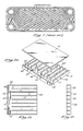
- FIG. 1 Another countercurrent system, Fig. 1, is that of Alfa-Laval described in the Proceedings of the 5th OTEC Conference, Miami, Florida (Feb. 1978) Pages VI 288-320.
- the Alfa-Laval concept consists mainly of a pack of thin metal plates, a frame and means of keeping the pieces together.
- the plates are suspended between horizontal carrying bars at top and bottom and compressed against the stationary frame plate by means of tightening bolts and a movable pressure plate.
- the frame plate is equipped with nozzles for inlet and outlet connections. Every plate is sealed around its perimeter with a gasket and cemented into a pressed track. Flow ports at each of the plate corners are individually gasketed and thus divide the interplate spaces into two systems of alternating flow channels.
- the plate which is the basic element of this concept, has a corrugated pattern stamped on it. These corrugations can be arranged to create an unlimited number of plate patterns. The specific pattern results from a careful trade-off between drop and convective heat transfer characteristics.
- the gaskets in the Alfa-Laval system are cemented to the plates in pressed tracks, and are generally made of elastomers like natural rubber, nitrile, butyl, neoprene, viton, etc.
- the material selection depends upon the working conditions, however, the upper limits are about 360 PSI and about 400°F.
- the present invention is based on the object of providing a heat exchanger of the above-mentioned type having a simple unitary design not requiring complicated inlet and outlet means.
- an internally manifolded fin plate for a plate/fin-type heat exchanger for a plate/fin-type heat exchanger.
- plate 10 be of unibody construction, a plurality of components may be connected to make up a single plate.
- Figs, 2a, 2b and 2c there is shown the basic unibody, one piece, fin plate 10 which comprises open-face 12, and side ports 14,14 transversely oriented through top edge 17 of fin plate 10.
- a schematic representation of an internally manifolded plate stack 30 comprising a plurality of internally manifolded fin plates 10.
- fin plates are stacked in a manner in alternating sequence. It should be noted, for each embodiment, that although the fins 22 are shown in a vertical line. they may be staggered, Fig. 7b. Also, although in the preferred operating conditions these fin plates are the same, the internal design on alternating fin plates may be varied to accomplish the desired thermodynamic effects.
- a first fluid is conveyed in through side ports 14 of alternating fin plates, into internal manifold 16, along channels 20 formed by fins 22, and exits through end ports 24.
- a second fluid of either higher or lower temperature is similarly introduced through the side ports 14 of the next alternating fin plate resulting in countercurrent flow.
- this is the preferred direction of flow, it is within the scope of this invention to have flow in a reverse manner wherein the fluid enters through end ports 24, flows down the channel 20 into the internal manifold 16, and exits through side port 14.
- the flow could also be parallel by introducing one fluid through the side port 14 and the other fluid through the end port 24 of the adjacent fin plate.
- the first and second fluids may be the same or different and that depending upon thermodynamic requirements, more than two fluids may be used.
- FIGs. 3a and 3b there is shown two additional embodiments of the internal manifolding means 16.
- Said manifolding means 16 may have a tapered geometery as defined by an angle 33.
- the internal manifold 16 has two side ports 14, 14 and the taper narrows as the fluid reaches mid-point 32. At mid-point 32 an optional barrier 34 can be inserted.
- the embodiment shows internal manifold 16 having one side port 14 and the taper goes across the full width of the fin plate narrowing as it reaches the closed side 23.
- FIG. 4a the fins 22 and channels 20 are randomly inserted within the main channel 20 of the basic fin plate 10.
- fin geometry in Figs. 4b and 4c shows inline intermittent fin geometries. Intermittent fin row can either be alternating as shown in Fig. 4b, or inline as shown in Fig. 4c.
- the channel surface may be either smooth or rough depending upon the specific design requirements, and it should be noted that no matter what fin geometry is used, the fins and channels are designed to enhance structural integrity as well as overall heat transfer performance. Also, channels may taper in both depth and width.
- a plurality of channel and fin shapes there is shown a plurality of channel and fin shapes.
- the most conventional channel and fin shape is that which is represented by channel 20 and fin 22.
- channels of different configurations such as those with rounded corners 36, U-shaped 38, V-shaped 40, and trapezoidal-shaped 42, along with their respective fin shapes are also within the scope of the invention.
- One critical feature of the present invention is that the channel and fins combine to enhance heat transfer and structural integrity while the channel itself is open-faced, thus allowing ease of manufacture.
- the channels themselves may be either smooth or rough, or corrugated or have any other surface goemetry which would enhance flow and heat transfer.
- Fin plate 62 is basically the same as fin plate 10, however, fin plate 62 additionally comprises closed end external manifold 64, open end external manifold 66, and two pairs of side manifolds 68, 70. Each pair of side manifolds comprise a side inlet manifold 68 and a diagonally located side closed manifold 70. All external manifolds are integral and contiguous with fin plate 10. Although external manifolds are shown with rectangular goemetries, any geometry capable of transferring fluid to and from the fin plate will work.
- FIG. 6b there is shown the top view of the internally and interiorly manifolded open-faced fin plate 63.
- Plate 63 is basically the same as fin 62, however, fin plate 63 additionally comprises closed end auxiliary manifold 64, open end auxiliarly manifold 66, two pairs of interior side manifolds 68, 70 and a pair of interior inlets 65.
- Each pair of interior side manifolds comprise a side inlet manifold 68 and a diagonally located side closed manifold 70.
- FIGs. 7a, 7b and 7c there is shown various views of an internally manifolded fin plate and plate stack assembly 72.
- fin plates are stacked in an opposed manner in alternating sequence.
- a first fluid is conveyed to inlet side manifold 68 wherein said fluid flows in through side port 14 along the internal manifolding means 16 and is turned to flow down channels 20 formed by fins 22.
- This first fluid then flows out end port 24 and into open end auxiliary manifold 66.
- From the auxiliary manifold 66 the first fluid is then conveyed to any appropriate location.
- a second fluid either warmer or cooler than the first fluid is conveyed into the adjacent fin plates through its respective side inlet manifold 68.
- the second fluid is conveyed in through entry port 14 along the internal manifold 16, down channels 20 and along fins 22. From there the second fluid exits into its respective open end secondary manifold 66 where it would be conveyed to any appropriate location.
- Closed end secondary manifolds 64 and side closed manifolds 70 are used to make continuous secondary manifolds between alternating fin plates. It should be noted that although the side and end manifolds are shown to be rectangular in shape, any functional shape will have the desired effect.
- heat exchanger fluids may be liquids or gases or combinations of liquids and gases.
- various plate thicknesses, channel and fin ratios, length and width ratios and various thermally conductive materials can be used.
- the following materials are. delineated by way of example; metals, ceramics polymers.
- the above design is the first real automated means for manufacturing heat exchangers. This will reduce the labor manhours involved in cutting, brazing, welding, leak checking, etc., compared to tube in shell and plate/fin heat exchangers. Moreover, the scaling of the design allowed provides a wide latitude of sizes, materials and fluids.
- each passage (cold or hot) has an adjacent passage (hot or cold) on each side.
- Bonded joint 11 between plates 10 permits the thermal conduction from plate to plate and thereby considerably enhances heat exchanger efficiency over a non-contacting joint design such as the Alfda-Laval concept.
- the tailoring of the coolant passages to provide variable flow area is allowed in the design, both in width and height with an appropriate change in wall and land thicknesses. In the basic heat exchange process, the best heat exchange efficiency is provided with a pure frictional flow process.
- the internal manifolding feature allows for both a minimum flow entrance loss and the internal manifold design provides for heat exchange within the manifold section, thus providing for the highest efficiency in a given length design.
Description
- The present invention relates to a heat exchanger in accordance with the prior art portion of
claim 1. - A heat exchanger having the features indicated in the prior art portion of
claim 1 is known by EP-A-44 561 (Fig. 10). This prior art heat exchanger requires complicated additional separate inlet and outlet means. The panel design comprises two different types of panels arranged alternatingly requiring the complicated inlet and outlet structure. - The plate/fin type heat exchangers are mainly of the channel and rib type construction. Countercurrent flow can be achieved. however. manifolding a plate stack which must separate the fluids at entry and exit becomes extremely complex. In that manifolding of the crosscurrent heat exchangers is comparatively simple, this heat exchanger system is more widely used although it is less efficient than the countercurrent system and it induces serious thermal and mechanical stresses.
- One countercurrent system which has attempted to solve the manifolding problem of the countercurrent heat exchanger is taught by Campbell et al. U.S. Patent 3.305,010. Campbell et al teach a heat exchanger having superposed stacked plate and fin elements and complex manifolding means for introducing fluids of different temperatures into opposite ends of the assembly. However, Campbell et al do not teach a plate which serves as both the plate and the fin, nor does Campbell et al teach means for internally manifolding the plate within the plate's plane.
- Another countercurrent system, Fig. 1, is that of Alfa-Laval described in the Proceedings of the 5th OTEC Conference, Miami, Florida (Feb. 1978) Pages VI 288-320. The Alfa-Laval concept consists mainly of a pack of thin metal plates, a frame and means of keeping the pieces together. The plates are suspended between horizontal carrying bars at top and bottom and compressed against the stationary frame plate by means of tightening bolts and a movable pressure plate. The frame plate is equipped with nozzles for inlet and outlet connections. Every plate is sealed around its perimeter with a gasket and cemented into a pressed track. Flow ports at each of the plate corners are individually gasketed and thus divide the interplate spaces into two systems of alternating flow channels. Through these, the two media pass, the warmer medium giving up heat to the cooler by conduction through the thin plates. This gasket arrangement eliminates the risk of media interleakage. The plate, which is the basic element of this concept, has a corrugated pattern stamped on it. These corrugations can be arranged to create an unlimited number of plate patterns. The specific pattern results from a careful trade-off between drop and convective heat transfer characteristics.
- The gaskets in the Alfa-Laval system are cemented to the plates in pressed tracks, and are generally made of elastomers like natural rubber, nitrile, butyl, neoprene, viton, etc. The material selection depends upon the working conditions, however, the upper limits are about 360 PSI and about 400°F.
- In view of this prior art, the present invention is based on the object of providing a heat exchanger of the above-mentioned type having a simple unitary design not requiring complicated inlet and outlet means.
- This object is achieved by a heat exchanger in accordance with the prior art portion of
claim 1 having the features indicated in the characterising portion thereof. -
- Fig. 1 is prior art. It is a top view of a prior art corrugated plate.
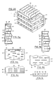
- Fig. 2a is a perspective schematic view of the open-faced internally manifolded fin plate.
- Fig. 2b is a top schematic view of the open-faced internally manifolded fin plate.
- Fig. 2c is an open-end schematic view of an open-faced internally manifolded plate.
- Fig. 2d is a prespective schematic view of an open-faced internally manifolded plate stack.
- Fig. 3a shows an additional schematic embodiment of the internal manifold for the open-faced internally manifolded plate.
- Fig. 3b shows another schematic embodiment of the internal manifold for the open-faced internally manifolded plate.
- Fig. 4a is the top view of another schematic embodiment of the fin-channel configuration.
- Fig. 4b is a top view of yet another schematic embodiment of the fin-channel configuration.
- Fig. 4c is a third schematic top view of a fin-channel configuration.
- Fig. 5 is a schematic end view of the open-faced internally manifolded fin plate showing various goemetries of channels and fins.
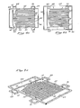
- Fig. 6a is a schematic top view of an open-faced internally manifolded fin plate having integral external side and end manifolds.
- Fig. 6b is another schematic top view of an open-faced internally manifolded fin plate having integral interior side and end manifolds.
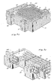
- Fig. 7a is a perspective view of a single internally and externally manifolded plate.
- Fig. 7b is a perspective view of the open-faced internally manifolded plate stack having side and end manifolds integrally connected with the open-faced internally manifolded plate.
- Fig. 7c is an enlarged fragmentary perspective showing relative proportions of fins, channels and manifolding means.
- In accordance with the present invention there is provided an internally manifolded fin plate for a plate/fin-type heat exchanger. Although it is preferred that
plate 10 be of unibody construction, a plurality of components may be connected to make up a single plate. Referring to Figs, 2a, 2b and 2c, there is shown the basic unibody, one piece,fin plate 10 which comprises open-face 12, andside ports fin plate 10. -
Side plates fin plate 10. Closedend 18 is adjacent to and lateral with the aft end of internal manifolding means 16.Channels 20 formed byfins 22 are contiguous with and transverse to the forward end of the manifolding means 16 and direct fluid flow to endports 24. Flat bottom 26 provides a heat transfer surface for connecting tofins 22 of an adjacent plate, means for separating fluids, as well as a means for sealably connecting thefin plates 10 in a plate stack. It should be noted that the plate stack can be used for high or low pressure situations and that internal leakage paths are non-critical.Plate cover 15 can either be solid, as shown, or merely anotherbasic fin plate 10. Additionally, Fig. 2b showsoptional manifold fins 28.Manifold fins 28 provide added support and additional means to transfer heat. - Referring now to Fig. 2d, there is shown a schematic representation of an internally manifolded plate stack 30 comprising a plurality of internally
manifolded fin plates 10. In the preferred operating condition, fin plates are stacked in a manner in alternating sequence. It should be noted, for each embodiment, that although thefins 22 are shown in a vertical line. they may be staggered, Fig. 7b. Also, although in the preferred operating conditions these fin plates are the same, the internal design on alternating fin plates may be varied to accomplish the desired thermodynamic effects. In the preferred operating sequence, a first fluid is conveyed in throughside ports 14 of alternating fin plates, intointernal manifold 16, alongchannels 20 formed byfins 22, and exits throughend ports 24. A second fluid of either higher or lower temperature is similarly introduced through theside ports 14 of the next alternating fin plate resulting in countercurrent flow. Although this is the preferred direction of flow, it is within the scope of this invention to have flow in a reverse manner wherein the fluid enters throughend ports 24, flows down thechannel 20 into theinternal manifold 16, and exits throughside port 14. The flow could also be parallel by introducing one fluid through theside port 14 and the other fluid through theend port 24 of the adjacent fin plate. It should be noted that the first and second fluids may be the same or different and that depending upon thermodynamic requirements, more than two fluids may be used. - Referring now to Figs. 3a and 3b, there is shown two additional embodiments of the internal manifolding means 16. Said manifolding means 16 may have a tapered geometery as defined by an
angle 33. In Fig. 3a, theinternal manifold 16 has twoside ports optional barrier 34 can be inserted. In Fig. 3b, the embodiment showsinternal manifold 16 having oneside port 14 and the taper goes across the full width of the fin plate narrowing as it reaches theclosed side 23. Although these are only three internal manifolding geometries displayed herein, any other internal manifold geometry which could channel the fluid from aside port 14 to thechannel 20 is within the scope of this invention. - Referring now to Figs. 4a, 4b and 4c, there is shown additional geometries for
fins 22 andchannels 20. In Fig. 4a, thefins 22 andchannels 20 are randomly inserted within themain channel 20 of thebasic fin plate 10. In contrast to that, fin geometry in Figs. 4b and 4c shows inline intermittent fin geometries. Intermittent fin row can either be alternating as shown in Fig. 4b, or inline as shown in Fig. 4c. The channel surface may be either smooth or rough depending upon the specific design requirements, and it should be noted that no matter what fin geometry is used, the fins and channels are designed to enhance structural integrity as well as overall heat transfer performance. Also, channels may taper in both depth and width. - Referring nowto Fig. 5, there is shown a plurality of channel and fin shapes. The most conventional channel and fin shape is that which is represented by
channel 20 andfin 22. However, channels of different configurations such as those withrounded corners 36, U-shaped 38, V-shaped 40, and trapezoidal-shaped 42, along with their respective fin shapes are also within the scope of the invention. One critical feature of the present invention is that the channel and fins combine to enhance heat transfer and structural integrity while the channel itself is open-faced, thus allowing ease of manufacture. Additionally, it should be noted that the channels themselves may be either smooth or rough, or corrugated or have any other surface goemetry which would enhance flow and heat transfer. - Referring now to Fig. 6a, there is shown the top view of the internally and auxiliary manifolded open-
faced fin plate 62.Fin plate 62 is basically the same asfin plate 10, however,fin plate 62 additionally comprises closed endexternal manifold 64, open endexternal manifold 66, and two pairs of side manifolds 68, 70. Each pair of side manifolds comprise aside inlet manifold 68 and a diagonally located side closedmanifold 70. All external manifolds are integral and contiguous withfin plate 10. Although external manifolds are shown with rectangular goemetries, any geometry capable of transferring fluid to and from the fin plate will work. - Referring now to Fig. 6b, there is shown the top view of the internally and interiorly manifolded open-
faced fin plate 63.Plate 63 is basically the same asfin 62, however,fin plate 63 additionally comprises closed endauxiliary manifold 64, openend auxiliarly manifold 66, two pairs of interior side manifolds 68, 70 and a pair ofinterior inlets 65. Each pair of interior side manifolds comprise aside inlet manifold 68 and a diagonally located side closedmanifold 70. - Referring now to Figs. 7a, 7b and 7c, there is shown various views of an internally manifolded fin plate and
plate stack assembly 72. In the preferred operating condition, fin plates are stacked in an opposed manner in alternating sequence. A first fluid is conveyed toinlet side manifold 68 wherein said fluid flows in throughside port 14 along the internal manifolding means 16 and is turned to flow downchannels 20 formed byfins 22. This first fluid then flows outend port 24 and into open endauxiliary manifold 66. From theauxiliary manifold 66 the first fluid is then conveyed to any appropriate location. A second fluid either warmer or cooler than the first fluid is conveyed into the adjacent fin plates through its respectiveside inlet manifold 68. Then, similarly to the flow of the first fluid, the second fluid is conveyed in throughentry port 14 along theinternal manifold 16, downchannels 20 and alongfins 22. From there the second fluid exits into its respective open endsecondary manifold 66 where it would be conveyed to any appropriate location. Closed endsecondary manifolds 64 and side closedmanifolds 70 are used to make continuous secondary manifolds between alternating fin plates. It should be noted that although the side and end manifolds are shown to be rectangular in shape, any functional shape will have the desired effect. Furthermore, heat exchanger fluids may be liquids or gases or combinations of liquids and gases. - Depending upon the ultimate use and desired heat transfer rate, various plate thicknesses, channel and fin ratios, length and width ratios and various thermally conductive materials can be used. The following materials are. delineated by way of example; metals, ceramics polymers.
- The above design is the first real automated means for manufacturing heat exchangers. This will reduce the labor manhours involved in cutting, brazing, welding, leak checking, etc., compared to tube in shell and plate/fin heat exchangers. Moreover, the scaling of the design allowed provides a wide latitude of sizes, materials and fluids.
- The basic technical merit provided by the design, presented in Fig. 7c, is that it allows a fundamental counterflow heat exchange design with all working surfaces having equal ΔT to the adjacent surface. As can be seen, each passage (cold or hot) has an adjacent passage (hot or cold) on each side. Bonded joint 11 between
plates 10, permits the thermal conduction from plate to plate and thereby considerably enhances heat exchanger efficiency over a non-contacting joint design such as the Alfda-Laval concept. The tailoring of the coolant passages to provide variable flow area is allowed in the design, both in width and height with an appropriate change in wall and land thicknesses. In the basic heat exchange process, the best heat exchange efficiency is provided with a pure frictional flow process. Any turbulence due to waviness, protuberances or roughness results in an inefficient pressure loss and an actual decrease in overall heat transfer. If heat exchanger compactness is basically desired, the heat exchange benefit of waviness, roughness, interrupted fins, etc., can be put into the IMPS design by coining, etching, milling, etc., at some expense to the flow pressure losses. The added advantage of a different groove size geometry with simple tooling changes becomes an added feature of the design. - The internal manifolding feature, as shown throughout the Figures, allows for both a minimum flow entrance loss and the internal manifold design provides for heat exchange within the manifold section, thus providing for the highest efficiency in a given length design.
Claims (5)
Priority Applications (2)
| Application Number | Priority Date | Filing Date | Title |
|---|---|---|---|
| EP19820105574 EP0097726B1 (en) | 1982-06-24 | 1982-06-24 | A heat exchanger |
| DE8282105574T DE3279938D1 (en) | 1982-06-24 | 1982-06-24 | A heat exchanger |
Applications Claiming Priority (1)
| Application Number | Priority Date | Filing Date | Title |
|---|---|---|---|
| EP19820105574 EP0097726B1 (en) | 1982-06-24 | 1982-06-24 | A heat exchanger |
Publications (2)
| Publication Number | Publication Date |
|---|---|
| EP0097726A1 EP0097726A1 (en) | 1984-01-11 |
| EP0097726B1 true EP0097726B1 (en) | 1989-09-13 |
Family
ID=8189100
Family Applications (1)
| Application Number | Title | Priority Date | Filing Date |
|---|---|---|---|
| EP19820105574 Expired EP0097726B1 (en) | 1982-06-24 | 1982-06-24 | A heat exchanger |
Country Status (2)
| Country | Link |
|---|---|
| EP (1) | EP0097726B1 (en) |
| DE (1) | DE3279938D1 (en) |
Families Citing this family (6)
| Publication number | Priority date | Publication date | Assignee | Title |
|---|---|---|---|---|
| FR2580794B1 (en) * | 1985-04-23 | 1989-05-19 | Inst Francais Du Petrole | THERMAL EXCHANGE DEVICE, ESPECIALLY FOR GAS EXCHANGES |
| DE3522095A1 (en) * | 1985-06-20 | 1987-01-02 | Stettner & Co | Apparatus for treating flowing media, and method for the manufacture thereof |
| EP0206067A1 (en) * | 1985-06-20 | 1986-12-30 | Stettner & Co. | Catalytic active structure comprising individual units and process for producing such units |
| DE19510847C2 (en) * | 1995-03-17 | 2002-11-21 | Michael Rehberg | Plate heat exchanger |
| SE534381C2 (en) * | 2009-12-08 | 2011-08-02 | Ny Kraft Sverige Ab | Heat exchanger with flow-controlling adhesive pattern and method of making it |
| CN115183611B (en) * | 2022-09-08 | 2022-11-18 | 中国核动力研究设计院 | Heat exchange component |
Family Cites Families (9)
| Publication number | Priority date | Publication date | Assignee | Title |
|---|---|---|---|---|
| DE143252C (en) * | ||||
| US1662870A (en) * | 1924-10-09 | 1928-03-20 | Stancliffe Engineering Corp | Grooved-plate heat interchanger |
| GB327377A (en) * | 1928-03-07 | 1930-04-03 | Richard Seligman | Improvements in or relating to plate heat exchange apparatus employing condensable gas or fluid |
| GB743201A (en) * | 1953-01-28 | 1956-01-11 | William Helmore | Improvements in or relating to heat exchangers |
| GB1048122A (en) * | 1966-08-12 | 1966-11-09 | Nicholson Terence Peter | Improvements in and relating to plate type heat exchangers |
| US3613782A (en) * | 1969-08-27 | 1971-10-19 | Garrett Corp | Counterflow heat exchanger |
| US3818984A (en) * | 1972-01-31 | 1974-06-25 | Nippon Denso Co | Heat exchanger |
| DE2706253A1 (en) * | 1977-02-15 | 1978-08-17 | Rosenthal Technik Ag | CERAMIC, RECUPERATIVE COUNTERFLOW HEAT EXCHANGER |
| EP0044561A3 (en) * | 1980-07-21 | 1982-07-14 | MüANYAGIPARI KUTATO INTEZET | Heat exchanger, in particular for heat exchange between gaseous fluids |
-
1982
- 1982-06-24 EP EP19820105574 patent/EP0097726B1/en not_active Expired
- 1982-06-24 DE DE8282105574T patent/DE3279938D1/en not_active Expired
Also Published As
| Publication number | Publication date |
|---|---|
| EP0097726A1 (en) | 1984-01-11 |
| DE3279938D1 (en) | 1989-10-19 |
Similar Documents
| Publication | Publication Date | Title |
|---|---|---|
| US4749032A (en) | Internally manifolded unibody plate for a plate/fin-type heat exchanger | |
| US4347896A (en) | Internally manifolded unibody plate for a plate/fin-type heat exchanger | |
| US4503908A (en) | Internally manifolded unibody plate for a plate/fin-type heat exchanger | |
| US4523638A (en) | Internally manifolded unibody plate for a plate/fin-type heat exchanger | |
| CN108700387B (en) | Battery cooling plate heat exchanger and plate assembly | |
| US4815534A (en) | Plate type heat exchanger | |
| US4804041A (en) | Heat-exchanger of plate fin type | |
| US4401155A (en) | Heat exchanger with extruded flow channels | |
| US8033326B2 (en) | Heat exchanger | |
| US20010054499A1 (en) | Corrugated fin with partial offset for a plate-type heat exchanger and corresponding plate-type heat exchanger | |
| US4893673A (en) | Entry port inserts for internally manifolded stacked, finned-plate heat exchanger | |
| CN100383485C (en) | Louvered fins for heat exchanger | |
| US4535840A (en) | Internally manifolded unibody plate for a plate/fin-type heat exchanger | |
| US4307779A (en) | Plate heat exchanger | |
| US4934455A (en) | Plate-fin heat exchanger | |
| EP0503080B1 (en) | Laminated heat exchanger | |
| US10436156B2 (en) | Air fin for a heat exchanger, and method of making the same | |
| US3759322A (en) | Heat exchanger | |
| EP0136481A2 (en) | Stacked plate/fin-type heat exchanger | |
| EP0097726B1 (en) | A heat exchanger | |
| US4475587A (en) | Heat exchanger | |
| EP0759139A1 (en) | Heat exchanger and method for its manufacture | |
| US20070235174A1 (en) | Heat exchanger | |
| JPH0372910B2 (en) | ||
| EP0203458A1 (en) | Heat-exchanger of plate fin type |
Legal Events
| Date | Code | Title | Description |
|---|---|---|---|
| PUAI | Public reference made under article 153(3) epc to a published international application that has entered the european phase |
Free format text: ORIGINAL CODE: 0009012 |
|
| AK | Designated contracting states |
Designated state(s): BE CH DE FR GB LI NL SE |
|
| 17P | Request for examination filed |
Effective date: 19840711 |
|
| GRAA | (expected) grant |
Free format text: ORIGINAL CODE: 0009210 |
|
| AK | Designated contracting states |
Kind code of ref document: B1 Designated state(s): BE CH DE FR GB LI NL SE |
|
| REF | Corresponds to: |
Ref document number: 3279938 Country of ref document: DE Date of ref document: 19891019 |
|
| ET | Fr: translation filed | ||
| PLBE | No opposition filed within time limit |
Free format text: ORIGINAL CODE: 0009261 |
|
| STAA | Information on the status of an ep patent application or granted ep patent |
Free format text: STATUS: NO OPPOSITION FILED WITHIN TIME LIMIT |
|
| 26N | No opposition filed | ||
| PGFP | Annual fee paid to national office [announced via postgrant information from national office to epo] |
Ref country code: FR Payment date: 19930517 Year of fee payment: 12 Ref country code: CH Payment date: 19930517 Year of fee payment: 12 |
|
| PGFP | Annual fee paid to national office [announced via postgrant information from national office to epo] |
Ref country code: SE Payment date: 19930521 Year of fee payment: 12 |
|
| PGFP | Annual fee paid to national office [announced via postgrant information from national office to epo] |
Ref country code: DE Payment date: 19930525 Year of fee payment: 12 Ref country code: BE Payment date: 19930525 Year of fee payment: 12 |
|
| PGFP | Annual fee paid to national office [announced via postgrant information from national office to epo] |
Ref country code: GB Payment date: 19930527 Year of fee payment: 12 |
|
| PGFP | Annual fee paid to national office [announced via postgrant information from national office to epo] |
Ref country code: NL Payment date: 19930630 Year of fee payment: 12 |
|
| PG25 | Lapsed in a contracting state [announced via postgrant information from national office to epo] |
Ref country code: GB Effective date: 19940624 |
|
| PG25 | Lapsed in a contracting state [announced via postgrant information from national office to epo] |
Ref country code: SE Effective date: 19940625 |
|
| PG25 | Lapsed in a contracting state [announced via postgrant information from national office to epo] |
Ref country code: LI Effective date: 19940630 Ref country code: CH Effective date: 19940630 Ref country code: BE Effective date: 19940630 |
|
| BERE | Be: lapsed |
Owner name: ROCKWELL INTERNATIONAL CORP. Effective date: 19940630 |
|
| PG25 | Lapsed in a contracting state [announced via postgrant information from national office to epo] |
Ref country code: NL Effective date: 19950101 |
|
| EUG | Se: european patent has lapsed |
Ref document number: 82105574.6 Effective date: 19950110 |
|
| NLV4 | Nl: lapsed or anulled due to non-payment of the annual fee | ||
| GBPC | Gb: european patent ceased through non-payment of renewal fee |
Effective date: 19940624 |
|
| PG25 | Lapsed in a contracting state [announced via postgrant information from national office to epo] |
Ref country code: FR Effective date: 19950228 |
|
| REG | Reference to a national code |
Ref country code: CH Ref legal event code: PL |
|
| PG25 | Lapsed in a contracting state [announced via postgrant information from national office to epo] |
Ref country code: DE Effective date: 19950301 |
|
| EUG | Se: european patent has lapsed |
Ref document number: 82105574.6 |
|
| REG | Reference to a national code |
Ref country code: FR Ref legal event code: ST |