EP0204501A2 - Golfschwungsimulator - Google Patents
Golfschwungsimulator Download PDFInfo
- Publication number
- EP0204501A2 EP0204501A2 EP86304049A EP86304049A EP0204501A2 EP 0204501 A2 EP0204501 A2 EP 0204501A2 EP 86304049 A EP86304049 A EP 86304049A EP 86304049 A EP86304049 A EP 86304049A EP 0204501 A2 EP0204501 A2 EP 0204501A2
- Authority
- EP
- European Patent Office
- Prior art keywords
- golf swing
- attachment means
- apertures
- arm
- axis
- Prior art date
- Legal status (The legal status is an assumption and is not a legal conclusion. Google has not performed a legal analysis and makes no representation as to the accuracy of the status listed.)
- Granted
Links
- 238000005266 casting Methods 0.000 claims abstract description 20
- 238000000465 moulding Methods 0.000 claims description 2
- 239000011343 solid material Substances 0.000 claims description 2
- 239000007787 solid Substances 0.000 abstract description 3
- 238000010276 construction Methods 0.000 description 1
- 238000006073 displacement reaction Methods 0.000 description 1
- 238000002474 experimental method Methods 0.000 description 1
- 238000003754 machining Methods 0.000 description 1
- 239000000463 material Substances 0.000 description 1
- 239000002184 metal Substances 0.000 description 1
- 230000000717 retained effect Effects 0.000 description 1
- 239000002023 wood Substances 0.000 description 1
- 210000000707 wrist Anatomy 0.000 description 1
Images
Classifications
-
- A—HUMAN NECESSITIES
- A63—SPORTS; GAMES; AMUSEMENTS
- A63B—APPARATUS FOR PHYSICAL TRAINING, GYMNASTICS, SWIMMING, CLIMBING, OR FENCING; BALL GAMES; TRAINING EQUIPMENT
- A63B69/00—Training appliances or apparatus for special sports
- A63B69/36—Training appliances or apparatus for special sports for golf
- A63B69/3621—Contacting or non-contacting mechanical means for guiding the swing
- A63B69/36211—Mechanical guides guiding the club head end during the complete swing, e.g. rails
- A63B69/36213—Mechanical guides guiding the club head end during the complete swing, e.g. rails with arm or rod fixed on the club and rotating around a fixed supporting point
Definitions
- This invention relates to equipment for practising the game of golf. More particularly it relates to the golf swing simulator disclosed in GB 2039221 and GB 2081107.
- a golf swing simulator device comprising a handle or mounting for a handle representing that of a golf club, attachment means for mounting the device to a stationary support, and a linkage connecting the handle with the attachment means, the linkage comprising an arm pivotally mounted at one end to the attachment means about a first axis, the arm extending away from said axis so that on pivoting the other end of the arm describes a circle about said first pivot axis, a crank one end of which is connected with said other end of the arm through a pivotal connection having a second axis of rotation preferably coplanar with but spaced from said first axis and the other end of which is rotatably mounted to the handle about the longitudinal axis of the handle so that the handle projecting from the crank is spaced from said pivotal connection in line with said second axis.
- That equipment further provides means for adjusting the effective length of the arm, means for adjustment of the angle that the first pivot axis makes with the horizontal, and means whereby the angle between the first and second axes can be adjusted.
- the simulator device provides three rotational axes; said first extending from the attachment means of the arm and about which the arm swings thereby establishing a swing plane; said second pivot axis acting between the free end of the arm and the handle to allow the wrists to pivot or "cock" during the stroke; and a third pivot axis extending longitudinally of the handle itself. It is believed that these three types of movement are essential for establishing a correct swing action.
- the equipment can also provide adjustment in the height of the attachment to the stationary support, and the angles which the first and second pivot axes make with the horizontal.
- the adjustment of the attachment height adapts to different users' arm length and different club standing heights, and also compensates for different swing plane angle settings; the setting of the first pivot axis allows the swing plane angle to be adjusted; and the setting of the second pivot axis allows the lie angle of the club to be set, or maintained when the first pivot axis is adjusted.
- Equipment of the type described above will obviously be useful in golf clubhouses, gymnasia and the like, where it would be used by many people.
- an individual once he has determined his optimum or preferred settings, might not need to adjust them thereafter, so that a market could arise for a somewhat simplified version of the equipment in which some or all of the adjustments were preset to suit the individual user.
- the user would still need to have initial access to the fully adjustable equipment so as to determine his parameters, but for this purpose he could use equipment owned by the golf club or a shop or the like.
- the height at which the attachment means has to be mounted on the support will be determined by the radius of swing, which is related to the user's arm length and which is in turn reflected by the effective length of the arm of the equipment and the club standing height.
- the support will not normally form part of the equipment, but could for example be a wall in a building, and once the attachment means is mounted to the wall, no further settting need be made. Consequently, such simplified equipment need not have any scale to indicate the height at which the mounting means has to be set; this could be determined merely by a conventional ruler.
- the attachment means itself would be connected to the arm by means of a pivotal joint articulating about the first pivot axis which makes a fixed angle with the horizontal, thereby determining the swing plane. It is likely, but in principle not essential, that the effective length of the arm will still be adjustable, thereby determining the radius of swing; and the angle made by the second pivot axis to the horizontal, which determines the lie angle, will also still be adjustable. There may be little or no merit in attempting to make these fixed; the arrangement shown in Fig. 5 of the drawings accompanying GB 2081107 representing a particularly advantageous arrangement for this region of the equipment. However, equipment could be offered with these settings also fixed according to predetermined values; so that the user armed with his particular parameters as determined on the variable simulator could buy a fixed setting simulator with those particular settings.
- the present invention provides a golf swing simulator device as described above having the three types of pivotal movement, but at least the angle which the first pivot axis makes with the horizontal being fixed.
- the present invention provides a golf swing simulator, wherein the attachment means comprises an integral moulding or casting having a rear face adapted for attachment to a support, and a body portion projecting forwardly from the rear face, the body having a central part of solid material extending rearwardly towards said rear face and through which a passage can be formed to accommodate a bearing for the pivotal joint with the arm within a range of possible angles which said first pivot axis can make with the horizontal.
- the range of angles suitably comprises 10 to 30° from the horizontal.
- it has a lower value which is at least 10° from the horizontal and an upper value which is not more than 30° from the horizontal.
- the attachment means is preferably provided with a marking to indicate the point from which the vertical height for mounting the attachment means to the support should be measured.
- the attachment means has a rear face for attachment to a support, with a plurality of apertures extending through the attachment means to said rear face to take securing screws or the like, at least two of said apertures being shaped to provide a relatively close fit for a screw of suitable size, and at least one of said apertures being vertically elongate so that the position of the screw in the aperture is adjustable.
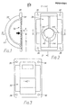
- the attachment means for pivotally mounting the arm of the device to a fixed support takes the form of an integral casting of suitable metal having a backing portion 30 and a body portion 32 projecting forwardly therefrom.
- the backing portion has a planar rear surface 34 to abut the surface of the support, for example a wall of a building, and the corners of the backing portion are provided with apertures 36 to take mounting screws or bolts for securing the casting to the supporting surface.
- the rear of the body portion is hollow, as shown at 38 in Figs 2, 4 and 5.
- the body portion is substantially rectangular in plan view (Fig. 4) but arcuate in side view (Figs 1, 5 and 6).
- the body portion has a solid central region 40 extending from a slightly downwardly sloping front face 42 and projecting into the hollow interior 38 of the body as far as the planar rear surface 34. Within the hollow region 38 the inwardly projecting portion of the central region is reinforced by webs 44.
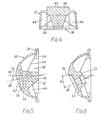
- the casting thus produced is then machined to accommodate a bearing for the pivotal joint with the arm (not shown).
- the pivot axis will be the axis 26 of the swing plane of the device, and makes an angle «with the horizontal, shown at 46.
- the angle ⁇ therefore has to be selected for the particular mounting in question, and Fig. 5 shows in broken lines the nature of the machining which has to be done.
- On the front surface of the body portion a new angled face 50 is machined normal to the pivot axis 26, and the rearwardly projecting part of the central portion is also cut back to a rear face 52 parallel to the plane 50 and spaced from it by the length of the bearing.
- a passage 54 for the bearing is then drilled between the two faces on the desired axis 26.
- Fig. 6 shows a cross- section through the finished casting prior to fitting the bearing, except that it is shown as having been formed with a greater angle cCthan shown in broken lines in Fig. 5, thereby illustrating that a range of angles is possible within the area of material provided by the solid central region 40 of the body.
- a greater angle @ will require the attachment means to be mounted at a greater height above the ground, it is convenient to mark the outside of the body with a datum point, the position of which varies according to the angle «, so that the user does not have to calculate a different height above the ground, but rather the deviation of the height from a given vertical setting will be compensated for by the positioning of the datum point.
- a series of graduations 56 are provided down one side of the body, and these are marked downwardly over the range 10 to 25, representing variations in the angle a from 10° to 25° from the horizontal.
- the body can be marked to show the actual angle ⁇ of its pivot axis 26, either by means of a separate marking on the body, or by putting a mark opposite the particular graduation on the scale 56. Alternatively, all the numerals on the scale 56 could be omitted except the one corresponding to the angled.
- the angle e is to be 17°
- the nominal height at which the device has to be mounted above the ground is h
- the attachment means is mounted to the support with the graduation 17 at that height h above the ground.
- the attachment means would have been mounted correspondingly lower, and had it been greater than 17°, the attachment means would have been mounted correspondingly higher.
- the body could be provided with a single mark as a datum point for setting its height on the support, according to what is determined to be the appropriate height from the fully variable simulator referred to above.
- the body having a fixed mark can be adjustably mounted on a wall plate which is fixed to the support, the wall plate having a scale, such as for example shown in Fig. 1 of EP 45660, against which the mark can register.
- the wall plate can have a similar construction to that shown in EP 45660, with a pair of restricted-mouth channels in which the heads of bolts are slidably retained, the bolts passing through the corner apertures 36 in the body 32 of the attachment means. When nuts are tightened onto thee bolts the body will be locked to the wall plate, but can be slid up and down by slackening the nuts.
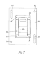
- Fig. 7 the casting of Figs. 1 to 6 is shown associated with a projecting plate 60.
- the casting can be integral with the plate, or the plate can be made for example of wood and the casting screwed to it through the corner apertures 36.
- the plate is provided with two circular apertures 62 in diagonally opposite corners, and two vertically elongate apertures 64 in the other two diagonally opposite corner regions.
- the plate is mounted to the wall or other support in the following manner.
- the plate is placed against the wall at the correct height, and marks are made on the wall through the elongate apertures 64, at about the middle of each aperture. Screws are inserted through the apertures at these points and into the wall and temporarily tightened so that the plate is held firm at. that position.
- the rest of the golf swing simulator is mounted to the attachment means 32 (unless it is already attached to it), and the standing height of the club is then checked relative to the ground.
- the screws in the elongate apertures 64 are slackened and the height of the plate 60 adjusted so that the club handle is at the correct standing height.
- the screws in the apertures 64 are then retightened and the screws are passed through the smaller apertures 62 into the wall and tightened so as to secure the plate at the correct position without the possibility of displacement.
Landscapes
- Engineering & Computer Science (AREA)
- Mechanical Engineering (AREA)
- Health & Medical Sciences (AREA)
- General Health & Medical Sciences (AREA)
- Physical Education & Sports Medicine (AREA)
- Golf Clubs (AREA)
- A Measuring Device Byusing Mechanical Method (AREA)
Applications Claiming Priority (2)
| Application Number | Priority Date | Filing Date | Title |
|---|---|---|---|
| GB858513478A GB8513478D0 (en) | 1985-05-29 | 1985-05-29 | Golf swing indicator device |
| GB8513478 | 1985-05-29 |
Publications (3)
| Publication Number | Publication Date |
|---|---|
| EP0204501A2 true EP0204501A2 (de) | 1986-12-10 |
| EP0204501A3 EP0204501A3 (en) | 1987-11-11 |
| EP0204501B1 EP0204501B1 (de) | 1990-08-22 |
Family
ID=10579808
Family Applications (1)
| Application Number | Title | Priority Date | Filing Date |
|---|---|---|---|
| EP86304049A Expired - Lifetime EP0204501B1 (de) | 1985-05-29 | 1986-05-28 | Golfschwungsimulator |
Country Status (3)
| Country | Link |
|---|---|
| EP (1) | EP0204501B1 (de) |
| DE (1) | DE3673569D1 (de) |
| GB (2) | GB8513478D0 (de) |
Family Cites Families (7)
| Publication number | Priority date | Publication date | Assignee | Title |
|---|---|---|---|---|
| US1500183A (en) * | 1923-05-31 | 1924-07-08 | Dall David Dewar | Golf-practice device |
| GB1009090A (en) * | 1962-11-16 | 1965-11-03 | David Hamilton Cockburn | Improvements in golf practice machines |
| GB1104085A (en) * | 1966-02-11 | 1968-02-21 | Reginald Valentine Wilks | Improvements in or relating to golf practice apparatus |
| GB1104203A (en) * | 1966-02-11 | 1968-02-21 | Reginald Valentine Wilks | Improvements in or relating to golf practice apparatus |
| GB1144180A (en) * | 1966-12-05 | 1969-03-05 | Reginald Valentine Wilks | Golf practice apparatus |
| GB2039221B (en) * | 1978-11-17 | 1982-09-22 | Richards R | Golf swing simulator |
| GB2081107B (en) * | 1980-08-06 | 1984-03-14 | Richards Ralph Henry Arthur | Golf swing simulator |
-
1985
- 1985-05-29 GB GB858513478A patent/GB8513478D0/en active Pending
-
1986
- 1986-05-28 GB GB8612932A patent/GB2175809B/en not_active Expired
- 1986-05-28 EP EP86304049A patent/EP0204501B1/de not_active Expired - Lifetime
- 1986-05-28 DE DE8686304049T patent/DE3673569D1/de not_active Expired - Lifetime
Also Published As
| Publication number | Publication date |
|---|---|
| EP0204501A3 (en) | 1987-11-11 |
| DE3673569D1 (de) | 1990-09-27 |
| GB2175809A (en) | 1986-12-10 |
| GB8513478D0 (en) | 1985-07-03 |
| GB8612932D0 (en) | 1986-07-02 |
| EP0204501B1 (de) | 1990-08-22 |
| GB2175809B (en) | 1989-07-05 |
Similar Documents
| Publication | Publication Date | Title |
|---|---|---|
| US5421098A (en) | Apparatus for adjusting golf club loft and lie | |
| US4194739A (en) | Adjustable golf putter | |
| US5762565A (en) | Golf swing training device | |
| US5244205A (en) | Adjustable lie angle golf club putter | |
| US4245392A (en) | Device for measuring and adjusting the lie and face of golf club | |
| US5722177A (en) | Golf club putter fitting apparatus and method | |
| US4261573A (en) | Golf swing simulator device | |
| US5154000A (en) | Conduit bending plane and bend angle indicator | |
| CA1216870A (en) | Device for controlling golf swing | |
| JPH0781805B2 (ja) | ゴルフクラブの測定装置 | |
| US5330179A (en) | Golfer's putting aid | |
| US4817294A (en) | Club head angle measuring instrument | |
| US4885847A (en) | Golf club measuring and fitting apparatus | |
| US4875293A (en) | Golf club measuring device | |
| EP0204501B1 (de) | Golfschwungsimulator | |
| US3727919A (en) | Golf club including image reflector attachment | |
| US4381111A (en) | Golf swing simulator device | |
| US3727920A (en) | Golf club attachment | |
| US4575090A (en) | Putting aid | |
| US4617820A (en) | Level calibrating device | |
| US4788774A (en) | Golf club measuring apparatus | |
| GB2081107A (en) | Golf swing simulator | |
| JPH02193001A (ja) | ゴルフクラブゲージ | |
| US4151650A (en) | Level assembly | |
| JP2795402B2 (ja) | ゴルフ用クラブの測定器 |
Legal Events
| Date | Code | Title | Description |
|---|---|---|---|
| PUAI | Public reference made under article 153(3) epc to a published international application that has entered the european phase |
Free format text: ORIGINAL CODE: 0009012 |
|
| AK | Designated contracting states |
Kind code of ref document: A2 Designated state(s): DE FR IT SE |
|
| PUAL | Search report despatched |
Free format text: ORIGINAL CODE: 0009013 |
|
| AK | Designated contracting states |
Kind code of ref document: A3 Designated state(s): DE FR IT SE |
|
| 17P | Request for examination filed |
Effective date: 19880312 |
|
| 17Q | First examination report despatched |
Effective date: 19881117 |
|
| GRAA | (expected) grant |
Free format text: ORIGINAL CODE: 0009210 |
|
| AK | Designated contracting states |
Kind code of ref document: B1 Designated state(s): DE FR IT SE |
|
| REF | Corresponds to: |
Ref document number: 3673569 Country of ref document: DE Date of ref document: 19900927 |
|
| ITF | It: translation for a ep patent filed | ||
| ET | Fr: translation filed | ||
| ITTA | It: last paid annual fee | ||
| PLBE | No opposition filed within time limit |
Free format text: ORIGINAL CODE: 0009261 |
|
| STAA | Information on the status of an ep patent application or granted ep patent |
Free format text: STATUS: NO OPPOSITION FILED WITHIN TIME LIMIT |
|
| 26N | No opposition filed | ||
| EAL | Se: european patent in force in sweden |
Ref document number: 86304049.9 |
|
| PGFP | Annual fee paid to national office [announced via postgrant information from national office to epo] |
Ref country code: FR Payment date: 19980514 Year of fee payment: 13 |
|
| PGFP | Annual fee paid to national office [announced via postgrant information from national office to epo] |
Ref country code: SE Payment date: 19980518 Year of fee payment: 13 |
|
| PGFP | Annual fee paid to national office [announced via postgrant information from national office to epo] |
Ref country code: DE Payment date: 19980520 Year of fee payment: 13 |
|
| PG25 | Lapsed in a contracting state [announced via postgrant information from national office to epo] |
Ref country code: SE Free format text: LAPSE BECAUSE OF NON-PAYMENT OF DUE FEES Effective date: 19990529 |
|
| EUG | Se: european patent has lapsed |
Ref document number: 86304049.9 |
|
| PG25 | Lapsed in a contracting state [announced via postgrant information from national office to epo] |
Ref country code: FR Free format text: LAPSE BECAUSE OF NON-PAYMENT OF DUE FEES Effective date: 20000131 |
|
| PG25 | Lapsed in a contracting state [announced via postgrant information from national office to epo] |
Ref country code: DE Free format text: LAPSE BECAUSE OF NON-PAYMENT OF DUE FEES Effective date: 20000301 |
|
| REG | Reference to a national code |
Ref country code: FR Ref legal event code: ST |
|
| PG25 | Lapsed in a contracting state [announced via postgrant information from national office to epo] |
Ref country code: IT Free format text: LAPSE BECAUSE OF NON-PAYMENT OF DUE FEES;WARNING: LAPSES OF ITALIAN PATENTS WITH EFFECTIVE DATE BEFORE 2007 MAY HAVE OCCURRED AT ANY TIME BEFORE 2007. THE CORRECT EFFECTIVE DATE MAY BE DIFFERENT FROM THE ONE RECORDED. Effective date: 20050528 |