EP0203241A1 - Multi-purpose pliers and their use in fastening, crimping, punching and similar operations - Google Patents
Multi-purpose pliers and their use in fastening, crimping, punching and similar operations Download PDFInfo
- Publication number
- EP0203241A1 EP0203241A1 EP85401005A EP85401005A EP0203241A1 EP 0203241 A1 EP0203241 A1 EP 0203241A1 EP 85401005 A EP85401005 A EP 85401005A EP 85401005 A EP85401005 A EP 85401005A EP 0203241 A1 EP0203241 A1 EP 0203241A1
- Authority
- EP
- European Patent Office
- Prior art keywords
- axis
- lever
- pliers
- blade
- sliding blade
- Prior art date
- Legal status (The legal status is an assumption and is not a legal conclusion. Google has not performed a legal analysis and makes no representation as to the accuracy of the status listed.)
- Ceased
Links
Images


Classifications
-
- B—PERFORMING OPERATIONS; TRANSPORTING
- B21—MECHANICAL METAL-WORKING WITHOUT ESSENTIALLY REMOVING MATERIAL; PUNCHING METAL
- B21D—WORKING OR PROCESSING OF SHEET METAL OR METAL TUBES, RODS OR PROFILES WITHOUT ESSENTIALLY REMOVING MATERIAL; PUNCHING METAL
- B21D39/00—Application of procedures in order to connect objects or parts, e.g. coating with sheet metal otherwise than by plating; Tube expanders
- B21D39/03—Application of procedures in order to connect objects or parts, e.g. coating with sheet metal otherwise than by plating; Tube expanders of sheet metal otherwise than by folding
- B21D39/034—Joining superposed plates by piercing
-
- B—PERFORMING OPERATIONS; TRANSPORTING
- B25—HAND TOOLS; PORTABLE POWER-DRIVEN TOOLS; MANIPULATORS
- B25B—TOOLS OR BENCH DEVICES NOT OTHERWISE PROVIDED FOR, FOR FASTENING, CONNECTING, DISENGAGING OR HOLDING
- B25B7/00—Pliers; Other hand-held gripping tools with jaws on pivoted limbs; Details applicable generally to pivoted-limb hand tools
- B25B7/12—Pliers; Other hand-held gripping tools with jaws on pivoted limbs; Details applicable generally to pivoted-limb hand tools involving special transmission means between the handles and the jaws, e.g. toggle levers, gears
- B25B7/123—Pliers; Other hand-held gripping tools with jaws on pivoted limbs; Details applicable generally to pivoted-limb hand tools involving special transmission means between the handles and the jaws, e.g. toggle levers, gears with self-locking toggle levers
-
- B—PERFORMING OPERATIONS; TRANSPORTING
- B25—HAND TOOLS; PORTABLE POWER-DRIVEN TOOLS; MANIPULATORS
- B25F—COMBINATION OR MULTI-PURPOSE TOOLS NOT OTHERWISE PROVIDED FOR; DETAILS OR COMPONENTS OF PORTABLE POWER-DRIVEN TOOLS NOT PARTICULARLY RELATED TO THE OPERATIONS PERFORMED AND NOT OTHERWISE PROVIDED FOR
- B25F1/00—Combination or multi-purpose hand tools
- B25F1/003—Combination or multi-purpose hand tools of pliers'-, scissors'- or wrench-type with at least one movable jaw
-
- B—PERFORMING OPERATIONS; TRANSPORTING
- B26—HAND CUTTING TOOLS; CUTTING; SEVERING
- B26B—HAND-HELD CUTTING TOOLS NOT OTHERWISE PROVIDED FOR
- B26B17/00—Hand cutting tools, i.e. with the cutting action actuated by muscle power with two jaws which come into abutting contact
- B26B17/02—Hand cutting tools, i.e. with the cutting action actuated by muscle power with two jaws which come into abutting contact with jaws operated indirectly by the handles, e.g. through cams or toggle levers
Landscapes
- Engineering & Computer Science (AREA)
- Mechanical Engineering (AREA)
- Life Sciences & Earth Sciences (AREA)
- Forests & Forestry (AREA)
- Gripping Jigs, Holding Jigs, And Positioning Jigs (AREA)
Abstract
Description
La présente invention concerne une nouvelle pince à fonctions multiples qui est destinée à permettre l'exécution de travaux d'usinage divers.The present invention relates to a new multi-function pliers which is intended to allow the execution of various machining jobs.
Dans de nombreux domaines de la technique, il est nécessaire de réaliser des assemblages ou de petits usinages directement sur un chantier.In many fields of technology, it is necessary to carry out assemblies or small machining directly on a site.
C'est le cas, notamment lors de travaux d'isolation de bâtiments anciens ou nouveaux, lorsqu'il est nécessaire de monter une armature métallique, constituée par des profilés en U, contre des murs qui doivent être revêtus à distance de panneaux isolants, par exemple de panneaux composites de plâtre et de mousse de résine synthétique.This is the case, especially when insulating old or new buildings, when it is necessary to mount a metal frame, made up of U-shaped profiles, against walls which must be coated at a distance from insulating panels, for example composite panels of plaster and synthetic resin foam.
Jusqu'à présent pour réunir ces profilés constitués en tôle mince, on est amené à les percer et à passer des vis et écrous. Il s'agit là d'opérations lentes, donc onéreuses, et il y a toujours un risque que les vis et écrous soient mal serrés ou se desserrent sous l'influence de vibrations diverses alors qu'elles sont devenues inaccessibles.Until now, to join these profiles made of thin sheet metal, we have to drill them and pass screws and nuts. These are slow operations, therefore expensive, and there is always a risk that the screws and nuts are loosely tightened or loosen under the influence of various vibrations while they have become inaccessible.
La pince de l'invention permet de réaliser des assemblages par agrafage et, le cas échéant, de réaliser lesdits agrafages de façon que les deux pièces assemblées ne puissent ni être glissées ni tournées l'une par rapport à l'autre.The pliers of the invention makes it possible to produce assemblies by stapling and, if necessary, to produce said staples so that the two assembled parts can neither be slid nor turned relative to one another.
Dans d'autres cas, il est nécessaire de pouvoir sertir un manchon, par exemple pour réunir deux câbles ou un câble à un ridoir.In other cases, it is necessary to be able to crimp a sleeve, for example to join two cables or a cable to a turnbuckle.
Dans d'autres cas également, on doit pouvoir pratiquer des trous dans des pièces métalliques pour le passage de goujons, de chevilles ou d'autres pièces. Des coupes peuvent devoir aussi être exécutées.In other cases also, we must be able to practice holes in metal parts for the passage of studs, dowels or other parts. Cuts may also need to be made.
La pince de l'invention permet d'exécuter ces différentes opérations de façon simple, extrêmement rapide, et cela par des opérateurs même non spécialisés.The clamp of the invention makes it possible to execute these various operations in a simple, extremely fast manner, and this by operators, even non-specialized.
Conformément à l'invention, la pince à fonctions multiples et son application à des opérations d'usinage du genre agrafage, sertissage, poinçonnage et analogue est caractérisée en ce qu'elle comporte un corps formant un manche muni d'une poignée, ledit corps supportant un levier muni d'une poignée, ledit levier formant une partie d'une genouillère pour la commande d'une lame coulissante guidée par le corps et disposée en regard d'une partie de travail d'une matrice également portée par le corps.According to the invention, the multi-function pliers and its application to machining operations of the stapling, crimping, punching and the like type is characterized in that it comprises a body forming a handle provided with a handle, said body supporting a lever provided with a handle, said lever forming a part of a toggle lever for controlling a sliding blade guided by the body and arranged opposite a working part of a matrix also carried by the body.
Diverses autres caractéristiques de l'invention ressortent d'ailleurs de la description détaillée qui suit.Various other characteristics of the invention will also emerge from the detailed description which follows.
Une forme de réalisation de l'objet de l'invention est représentée, à titre d'exemple non limitatif, au dessin annexé.An embodiment of the object of the invention is shown, by way of nonlimiting example, in the accompanying drawing.
La fig. 1 est une élévation, en partie arrachée, de la pince à fonctions multiples de l'invention.Fig. 1 is an elevation, partially broken away, of the multifunction pliers of the invention.
La fig. 2 est une vue de dessous correspondant à la fig. 1.Fig. 2 is a bottom view corresponding to FIG. 1.
La fig. 3 est une perspective, à plus grande échelle, de la partie antérieure de la pince.Fig. 3 is a perspective, on a larger scale, of the front part of the clamp.
La fig. 4 est une coupe, à plus grande échelle, vue suivant la ligne IV-IV de la fig. 1.Fig. 4 is a section, on a larger scale, seen along the line IV-IV of FIG. 1.
La fig. 5 est une élévation partielle très agrandie, illustrant un détail de réalisation de la pince lorsqu'elle est conçue en tant que pince à agrafer.Fig. 5 is a very enlarged partial elevation, illustrating a detail of embodiment of the pliers when it is designed as stapling pliers.
La fig. 6 est une coupe d'une agrafe réalisée par la pince.Fig. 6 is a section through a clip produced by the pliers.
La fig. 7 illustre l'application des agrafes réalisées par la pince à la réunion de pièces métalliques.Fig. 7 illustrates the application of the staples produced by the pliers to the meeting of metal parts.
La fig. 8 est une élévation analogue à la fig. 5, montrant la pince munie d'un outil de sertissage.Fig. 8 is an elevation similar to FIG. 5, showing the pliers provided with a crimping tool.
La fig. 9 illustre un sertissage réalisé par la pince dans sa configuration de la fig. 8.Fig. 9 illustrates a crimping performed by the pliers in its configuration of FIG. 8.
La fig. 10 est une élévation analogue aux fig. 5 ou 8, montrant la pince munie d'un outil de poinçonnage.Fig. 10 is an elevation similar to FIGS. 5 or 8, showing the pliers provided with a punching tool.
La pince comporte un corps 1 constitué par exemple en tôle pliée pour présenter en section sensiblement la forme de la lettre U.The clamp comprises a body 1 made for example of folded sheet metal to present in section substantially the shape of the letter U.
Le corps forme un manche 2 à l'extrémité duquel est montée une poignée 3. A sa partie antérieure, le corps délimite une semelle plane 4 présentant éventuellement une lumière 5 pouvant faciliter le montage et le démontage d'un outil.The body forms a
A sa partie avant, le corps 1 délimite deux côtés 6, 7 présentant des boutonnières 8 dans lesquelles peut être déplacé un axe 9 porté par l'extrémité d'un levier 10 muni d'une poignée 11. L'axe 9 traverse une lame coulissante 12 dont l'extrémité 13 forme ou supporte un outil fixe ou amovible.At its front part, the body 1 delimits two
Le levier 10 supporte, par un axe 14 maintenu entre les côtés 6, 7 du corps 1, une extrémité de deux biellettes 15,16 dont l'autre extrémité est articulée sur un axe 17 porté par les côtés 6, 7. L'axe 17 est passé dans une lumière 18 que présente la lame 12.The
Pour que les biellettes 15, 16 soient bien maintenues parallèles, une bague entretoise 19, fig. 4, est enfilée sur l'axe 14 entre lesdites deux biellettes et des bagues entretoises 20, 21 sont enfilées sur l'axe 9 entres les biellettes et les deux côtés 10a, 10b du levier 10 qui présente, en section, la forme de la lettre U.So that the
Comme cela ressort de ce qui précède, le levier 10 forme avec les biellettes 15, 16 une genouillère qui permet de déplacer la lame 12 dans un mouvement alternatif.As is apparent from the above, the
Lorsque le levier 10 est pivoté dans le sens de la flèche f1, il prend appui contre le corps 1 par l'axe 17 de sorte que l'amplitude du mouvement d'avance, suivant la flèche f2 de la lame 12, est tout d'abord relativement importante pour un faible angle de pivotement du levier 10, cette amplitude décroissant au fur et à mesure du pivotement pour devenir très faible en fin de course, c'est-à-dire lorsque le levier 10 est rapproché du manche 2. La force exercée en fin de course est donc très importante.When the
A leur partie antérieure, les côtés 6, 7 du corps 1 sont conformés pour délimiter des platines 6a, 7a, par exemple percées de trous 22 pour le passage de vis ou autres organes de fixation également passés dans des trous 23 d'une matrice 24.At their front part, the
La matrice 24 est constituée par une ferrure en U conformée en col de cygne et pouvant emboîter les platines 6a, 7a pour être fixée solidement au corps 1. La matrice 24 forme à sa partie inférieure un outil 25 complémentaire à l'outil 26 formé ou rapporté sur l'extrémité 13 de la lame coulissante 12. Pour permettre le changement rapide de la lame coulissante 12, il est avantageux de constituer les axes 9 et 17 par des boulons et écrous, comme cela est illustré par les fig. 2 et 4.The
Dans le mode de réalisation des fig. 1 à 5, l'outil 26 forme une pointe de découpe 27 puis des bords de cambrage 28. L'outil 25 de la matrice 24 est complémentaire, c'est-à-dire qu'il délimite deux contre-lames d'appui entre lesquelles l'outil 26 peut être inséré.In the embodiment of FIGS. 1 to 5, the
Comme le montrent les fig. 5 et 6 lorsqu'on actionne la pince pour faire avancer l'outil 26 après avoir introduit deux tôles métalliques superposées 29, 30, celles-ci prennent appui contre la partie formant outil de la matrice, puis la pointe 27 de la lame 12 sectionne les deux tôles en formant un crevé 31 dont les côtés sont cambrés ensuite par les bords de cambrage 28 pour former des picots arrondis 32, 33.As shown in fig. 5 and 6 when the clamp is actuated to advance the
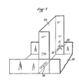
La fig. 7 illustre l'application du travail décrit ci-dessus à la réunion de deux profilés en U 34, 35, les picots 32 étant par exemple formés à l'intérieur des ailes du profilé 34 pour ne pas faire saillie en dehors des ailes du profilé 35.Fig. 7 illustrates the application of the work described above to the meeting of two U-shaped
En utilisant une lame coulissante 12 dont l'extrémité formant outil est plane, le crevé 31 à picots cambrés est rectangulaire, ce qui a pour effet que la liaison réalisée par les picots empêche tout déplacement, non seulement en translation des tôles assemblées mais aussi en rotation.By using a
Les fig. 8 et 9 montrent une réalisation dans laquelle la lame 12 délimite une encoche 36 et il est en est de même des extrémités de la matrice qui délimitent des encoches 37. Il devient ainsi possible, comme l'illustre la fig. 9, de sertir un manchon 38 sur deux extrémités de câbles 39, 40 ou d'autres pièces.Figs. 8 and 9 show an embodiment in which the
Si on le désire, la matrice 24 peut être conformée pour délimiter un trou 41 tandis que la lame 12 forme un emporte-pièce 42. D'autres types d'outils peuvent éventuellement être réalisés.If desired, the
L'invention n'est pas limitée à l'exemple de réalisation représenté et décrit en détail, car diverses modifications peuvent y être apportées sans sortir de son cadre.The invention is not limited to the embodiment shown and described in detail, since various modifications can be made without departing from its scope.
Claims (15)
Priority Applications (1)
| Application Number | Priority Date | Filing Date | Title |
|---|---|---|---|
| EP85401005A EP0203241A1 (en) | 1985-05-21 | 1985-05-21 | Multi-purpose pliers and their use in fastening, crimping, punching and similar operations |
Applications Claiming Priority (1)
| Application Number | Priority Date | Filing Date | Title |
|---|---|---|---|
| EP85401005A EP0203241A1 (en) | 1985-05-21 | 1985-05-21 | Multi-purpose pliers and their use in fastening, crimping, punching and similar operations |
Publications (1)
| Publication Number | Publication Date |
|---|---|
| EP0203241A1 true EP0203241A1 (en) | 1986-12-03 |
Family
ID=8194519
Family Applications (1)
| Application Number | Title | Priority Date | Filing Date |
|---|---|---|---|
| EP85401005A Ceased EP0203241A1 (en) | 1985-05-21 | 1985-05-21 | Multi-purpose pliers and their use in fastening, crimping, punching and similar operations |
Country Status (1)
| Country | Link |
|---|---|
| EP (1) | EP0203241A1 (en) |
Cited By (7)
| Publication number | Priority date | Publication date | Assignee | Title |
|---|---|---|---|---|
| FR2741830A1 (en) * | 1995-12-05 | 1997-06-06 | Pierre Grehal Et Compagnie Sa | Multi-function pliers used in sheet metal working |
| EP0865880A1 (en) | 1996-12-09 | 1998-09-23 | Etablissements Pierre Grehal Et Compagnie Sa | Multifunctional pliers |
| DE19807737A1 (en) * | 1998-02-24 | 1999-09-02 | Wezag Gmbh | Pliers for compressing workpieces, especially for producing solderless crimped connections |
| WO2000054903A1 (en) * | 1999-03-17 | 2000-09-21 | Andrzej Szulc | A method of joining metal sheet elements and a tool for joining metal sheet elements |
| DE102006006992B3 (en) * | 2006-02-15 | 2007-05-31 | Karl Jung Gmbh | Nipper for sheet metal processing in dry construction, has toggle lever arrangement which comprises connecting lever for direct transmission of the pivoting of moving arm on punch |
| FR3012056A1 (en) * | 2013-10-21 | 2015-04-24 | Grehal Pierre Ets Cie Sa | PUSH-PUSH MECHANISM FOR HAND TOOL, CRIMPING CLIPPER PROVIDED WITH SUCH A MECHANISM AND CRIMPING METHOD |
| FR3017553A1 (en) * | 2014-02-19 | 2015-08-21 | Grehal Pierre Ets Cie Sa | PUNCH FOR A CRIMPING TOOL AND CRIMPING TOOL PROVIDED WITH SUCH PUNCH. |
Citations (8)
| Publication number | Priority date | Publication date | Assignee | Title |
|---|---|---|---|---|
| FR502048A (en) * | 1919-05-22 | 1920-05-01 | William Louis Bessolo | Quick adjustment wrench |
| US2417013A (en) * | 1945-05-21 | 1947-03-04 | Petersen William | Toggle actuated sliding jaw wrench |
| US2481435A (en) * | 1945-10-09 | 1949-09-06 | Meunier Charles | Leverage wrench |
| US2519630A (en) * | 1946-08-12 | 1950-08-22 | Elizabeth M Boyer | Plier wrench |
| US3261073A (en) * | 1965-06-02 | 1966-07-19 | Karl J Klenk | Clinching punch |
| DE2559656A1 (en) * | 1975-12-06 | 1977-06-08 | Pressmaster Ag | ARRANGEMENT WITH AN ADJUSTABLE KNEE LEVER MECHANISM, IN PARTICULAR FOR PLIERS AND THE LIKE. |
| DE2902344A1 (en) * | 1979-01-22 | 1980-08-07 | Amphenol Tuchel Elect | Compression tool for forming crimped conductor connection - has moving shank with toggle lever one end of which slides in long bore of shank with stop |
| EP0103912A1 (en) * | 1982-08-26 | 1984-03-28 | C.A. Weidmüller GmbH & Co. | Pliers device |
-
1985
- 1985-05-21 EP EP85401005A patent/EP0203241A1/en not_active Ceased
Patent Citations (8)
| Publication number | Priority date | Publication date | Assignee | Title |
|---|---|---|---|---|
| FR502048A (en) * | 1919-05-22 | 1920-05-01 | William Louis Bessolo | Quick adjustment wrench |
| US2417013A (en) * | 1945-05-21 | 1947-03-04 | Petersen William | Toggle actuated sliding jaw wrench |
| US2481435A (en) * | 1945-10-09 | 1949-09-06 | Meunier Charles | Leverage wrench |
| US2519630A (en) * | 1946-08-12 | 1950-08-22 | Elizabeth M Boyer | Plier wrench |
| US3261073A (en) * | 1965-06-02 | 1966-07-19 | Karl J Klenk | Clinching punch |
| DE2559656A1 (en) * | 1975-12-06 | 1977-06-08 | Pressmaster Ag | ARRANGEMENT WITH AN ADJUSTABLE KNEE LEVER MECHANISM, IN PARTICULAR FOR PLIERS AND THE LIKE. |
| DE2902344A1 (en) * | 1979-01-22 | 1980-08-07 | Amphenol Tuchel Elect | Compression tool for forming crimped conductor connection - has moving shank with toggle lever one end of which slides in long bore of shank with stop |
| EP0103912A1 (en) * | 1982-08-26 | 1984-03-28 | C.A. Weidmüller GmbH & Co. | Pliers device |
Cited By (14)
| Publication number | Priority date | Publication date | Assignee | Title |
|---|---|---|---|---|
| FR2741830A1 (en) * | 1995-12-05 | 1997-06-06 | Pierre Grehal Et Compagnie Sa | Multi-function pliers used in sheet metal working |
| EP0865880A1 (en) | 1996-12-09 | 1998-09-23 | Etablissements Pierre Grehal Et Compagnie Sa | Multifunctional pliers |
| DE19807737A1 (en) * | 1998-02-24 | 1999-09-02 | Wezag Gmbh | Pliers for compressing workpieces, especially for producing solderless crimped connections |
| US6026671A (en) * | 1998-02-24 | 2000-02-22 | Wezag Gmbh Werkzeugfabrik | Pliers for crimping workpieces |
| DE19807737C2 (en) * | 1998-02-24 | 2000-06-21 | Wezag Gmbh | Pliers for pressing workpieces |
| WO2000054903A1 (en) * | 1999-03-17 | 2000-09-21 | Andrzej Szulc | A method of joining metal sheet elements and a tool for joining metal sheet elements |
| DE102006006992B3 (en) * | 2006-02-15 | 2007-05-31 | Karl Jung Gmbh | Nipper for sheet metal processing in dry construction, has toggle lever arrangement which comprises connecting lever for direct transmission of the pivoting of moving arm on punch |
| FR3012056A1 (en) * | 2013-10-21 | 2015-04-24 | Grehal Pierre Ets Cie Sa | PUSH-PUSH MECHANISM FOR HAND TOOL, CRIMPING CLIPPER PROVIDED WITH SUCH A MECHANISM AND CRIMPING METHOD |
| WO2015059635A1 (en) * | 2013-10-21 | 2015-04-30 | Etablissements Pierre Grehal Et Cie Sa | Hand tool step drive mechanism, crimping pliers provided with such a mechanism, and crimping method |
| US20160279765A1 (en) * | 2013-10-21 | 2016-09-29 | Etablissements Pierre Grehal Et Cie Sa | Hand tool step drive mechanism, crimping pliers provided with such a mechanism and crimping method |
| US10195721B2 (en) | 2013-10-21 | 2019-02-05 | Etablissements Pierre Grehal Et Cie Sa | Hand tool step drive mechanism and crimping method |
| FR3017553A1 (en) * | 2014-02-19 | 2015-08-21 | Grehal Pierre Ets Cie Sa | PUNCH FOR A CRIMPING TOOL AND CRIMPING TOOL PROVIDED WITH SUCH PUNCH. |
| WO2015124849A1 (en) * | 2014-02-19 | 2015-08-27 | Établissements Pierre Gréhal Et Cie Sa | Punch for crimping tool, and crimping tool provided with such a punch |
| US9999914B2 (en) | 2014-02-19 | 2018-06-19 | Etablissements Pierre Grehal Et Cie Sa | Punch for crimping tool and crimping tool provided with such a punch |
Similar Documents
| Publication | Publication Date | Title |
|---|---|---|
| CA2630958C (en) | Adjustable roller frame | |
| EP0698450B2 (en) | Cutting pliers for plastic profiles, rubber gaskets and the like | |
| EP0203241A1 (en) | Multi-purpose pliers and their use in fastening, crimping, punching and similar operations | |
| FR2535913A1 (en) | DRIPPER CLAMP FOR END OF CONDUCTORS | |
| EP0090773A1 (en) | Saw chain cutter link | |
| KR100971033B1 (en) | Quick adjustable pipe wrench | |
| EP0792704A1 (en) | Method of making wiper blades | |
| EP1065771B1 (en) | Rung or rail for cable ladder, cable ladder and mounting method | |
| EP1728568B1 (en) | Crimping pliers | |
| EP0159255B1 (en) | Plug grip for fitting expansion plugs comprising two articulated arms | |
| KR100919768B1 (en) | Tool for removing tip of spot welder | |
| FR2747955A1 (en) | TILE CUTTING DEVICE OF THE ROUND CUT TYPE | |
| EP1916063B1 (en) | Pliers | |
| JP2014100007A (en) | Wire cutting tool | |
| WO2008071750A1 (en) | Tweezers with interchangeable tips | |
| FR2674461A1 (en) | TIGHTENING PLIERS FOR PIPES AND THE LIKE. | |
| FR2893340A1 (en) | Suspension component, especially for suspended ceiling supporting frame, has one end shaped to engage with timber support and other receiving frame bracket | |
| EP0555443A1 (en) | Vise-grip wrench | |
| EP0317462B1 (en) | Staple-removing device, and method for its manufacture | |
| FR2669508A1 (en) | Safety device for scoring bread dough | |
| KR200465294Y1 (en) | Plier | |
| JP5631132B2 (en) | Operation chain connection tool | |
| FR2707539A1 (en) | Hand-held punch | |
| US6073922A (en) | Clamp apparatus | |
| JP3066572B2 (en) | Rod support structure for remote control device |
Legal Events
| Date | Code | Title | Description |
|---|---|---|---|
| PUAI | Public reference made under article 153(3) epc to a published international application that has entered the european phase |
Free format text: ORIGINAL CODE: 0009012 |
|
| 17P | Request for examination filed |
Effective date: 19850524 |
|
| AK | Designated contracting states |
Kind code of ref document: A1 Designated state(s): AT BE CH DE FR GB IT LI LU NL SE |
|
| 17Q | First examination report despatched |
Effective date: 19870320 |
|
| STAA | Information on the status of an ep patent application or granted ep patent |
Free format text: STATUS: THE APPLICATION HAS BEEN REFUSED |
|
| 18R | Application refused |
Effective date: 19880314 |
|
| RIN1 | Information on inventor provided before grant (corrected) |
Inventor name: MALAGNOUX, ROGER |