EP0202970B1 - Dispositif à piston pour la mesure très précise des pressions de fluide - Google Patents
Dispositif à piston pour la mesure très précise des pressions de fluide Download PDFInfo
- Publication number
- EP0202970B1 EP0202970B1 EP86400778A EP86400778A EP0202970B1 EP 0202970 B1 EP0202970 B1 EP 0202970B1 EP 86400778 A EP86400778 A EP 86400778A EP 86400778 A EP86400778 A EP 86400778A EP 0202970 B1 EP0202970 B1 EP 0202970B1
- Authority
- EP
- European Patent Office
- Prior art keywords
- piston
- pressure
- cylinder
- measured
- fluid
- Prior art date
- Legal status (The legal status is an assumption and is not a legal conclusion. Google has not performed a legal analysis and makes no representation as to the accuracy of the status listed.)
- Expired
Links
- 239000012530 fluid Substances 0.000 title claims abstract description 24
- 238000005259 measurement Methods 0.000 title abstract description 29
- 230000008878 coupling Effects 0.000 claims description 11
- 238000010168 coupling process Methods 0.000 claims description 11
- 238000005859 coupling reaction Methods 0.000 claims description 11
- 238000004891 communication Methods 0.000 claims description 2
- 239000012535 impurity Substances 0.000 claims description 2
- 238000009530 blood pressure measurement Methods 0.000 description 10
- 230000005540 biological transmission Effects 0.000 description 8
- 239000000523 sample Substances 0.000 description 8
- 238000013519 translation Methods 0.000 description 7
- 230000007423 decrease Effects 0.000 description 4
- 238000007789 sealing Methods 0.000 description 4
- 238000006243 chemical reaction Methods 0.000 description 3
- 208000031968 Cadaver Diseases 0.000 description 2
- 238000004140 cleaning Methods 0.000 description 2
- 230000006866 deterioration Effects 0.000 description 2
- 238000006073 displacement reaction Methods 0.000 description 2
- 230000000694 effects Effects 0.000 description 2
- 239000011521 glass Substances 0.000 description 2
- 238000005461 lubrication Methods 0.000 description 2
- -1 polytetrafluoroethylene Polymers 0.000 description 2
- UONOETXJSWQNOL-UHFFFAOYSA-N tungsten carbide Chemical compound [W+]#[C-] UONOETXJSWQNOL-UHFFFAOYSA-N 0.000 description 2
- RYGMFSIKBFXOCR-UHFFFAOYSA-N Copper Chemical compound [Cu] RYGMFSIKBFXOCR-UHFFFAOYSA-N 0.000 description 1
- 230000000712 assembly Effects 0.000 description 1
- 238000000429 assembly Methods 0.000 description 1
- 230000000903 blocking effect Effects 0.000 description 1
- 230000008859 change Effects 0.000 description 1
- 230000001143 conditioned effect Effects 0.000 description 1
- 238000010276 construction Methods 0.000 description 1
- 229910052802 copper Inorganic materials 0.000 description 1
- 239000010949 copper Substances 0.000 description 1
- 239000013078 crystal Substances 0.000 description 1
- 238000007872 degassing Methods 0.000 description 1
- 239000002274 desiccant Substances 0.000 description 1
- 239000006185 dispersion Substances 0.000 description 1
- 230000009977 dual effect Effects 0.000 description 1
- 230000005484 gravity Effects 0.000 description 1
- 239000004519 grease Substances 0.000 description 1
- 238000002513 implantation Methods 0.000 description 1
- 230000006698 induction Effects 0.000 description 1
- 239000011810 insulating material Substances 0.000 description 1
- 238000002955 isolation Methods 0.000 description 1
- 239000000314 lubricant Substances 0.000 description 1
- 238000003754 machining Methods 0.000 description 1
- 230000005415 magnetization Effects 0.000 description 1
- 210000000056 organ Anatomy 0.000 description 1
- 230000008520 organization Effects 0.000 description 1
- 229920001296 polysiloxane Polymers 0.000 description 1
- 229920001343 polytetrafluoroethylene Polymers 0.000 description 1
- 239000004810 polytetrafluoroethylene Substances 0.000 description 1
- 230000036316 preload Effects 0.000 description 1
- 230000009467 reduction Effects 0.000 description 1
- 238000012552 review Methods 0.000 description 1
- 230000035945 sensitivity Effects 0.000 description 1
- 229910001220 stainless steel Inorganic materials 0.000 description 1
- 239000010935 stainless steel Substances 0.000 description 1
- 239000013589 supplement Substances 0.000 description 1
- 230000009466 transformation Effects 0.000 description 1
- 238000012795 verification Methods 0.000 description 1
Images

Classifications
-
- G—PHYSICS
- G01—MEASURING; TESTING
- G01L—MEASURING FORCE, STRESS, TORQUE, WORK, MECHANICAL POWER, MECHANICAL EFFICIENCY, OR FLUID PRESSURE
- G01L27/00—Testing or calibrating of apparatus for measuring fluid pressure
- G01L27/002—Calibrating, i.e. establishing true relation between transducer output value and value to be measured, zeroing, linearising or span error determination
- G01L27/005—Apparatus for calibrating pressure sensors
Definitions
- the present invention relates to the measurement of fluid pressures, in particular of gas, with very high precision.
- Its purpose is to produce a device which makes it possible to perform very precise measurement of both an absolute pressure and a relative pressure (relative to atmospheric pressure), or even a difference in pressures (difference between the pressures of two fluids).
- the apparatus according to the invention may in particular constitute a pressure standard, capable of carrying out the verification and calibration of the manometers, or a pressure sensor or transmitter.
- the device according to this prior French patent actually measured a relative pressure, namely that of a fluid applied to the upper face of said piston, with respect to the atmospheric pressure which acted on the lower face of this piston.
- European application EP-AI 0 112 647 published on July 4, 1984 describes a pressure measurement device comprising a piston, one end of which is applied the pressure to be measured and the other end of which is applied against the movable part. a precision balance, said piston being able to move longitudinally in a sleeve which is driven in rotation, the piston being itself fixed in rotation.
- Such a device is actually a variant of device described in the aforementioned French patent No. 2,481,801, rotation of the piston into the cylinder provided in this Patent No. 2,481,801 is replaced by the rotation of the sleeve (cylinder making office ) around the piston in the European application No. 0 112 647.
- the present invention aims to achieve a standard for measuring a fluid pressure, in particular the absolute pressure of a gas, by providing for the application on the upper face of a piston for measuring the pressure, rotating in a cylinder, the pressure to be measured while making it possible to apply to the underside of the pressure measuring piston, according to the desired use, either the vacuum (to perform an absolute pressure measurement), or the atmospheric pressure (to perform a relative pressure measurement, compared to this atmospheric pressure), or another desired pressure (to perform a pressure difference measurement).
- the subject of the invention is a device for very precise measurement of the fluid pressures with display of the measured pressure, comprising a vertical cylinder, a piston able to slide in this viscous friction cylinder, the pressure to be measured being applied to the upper face of the piston in an upper enclosure, means for rotating said piston in said cylinder, a precision electromagnetic dynamometric balance with display and comprising a part intended to be applied the force to be measured and means for transmitting to the part of the balance the force applied to the piston by the pressure to be measured, with limitation of the maximum forces, device characterized in that it comprises, in combination with the cylinder-piston assembly: a sealed enclosure lower than the part lower of the cylinder-piston assembly, this lower enclosure being able to be put under vacuum or put under a desired pressure in particular the pressio n atmospheric or that of a fluid; and means for permanently supplying, in a fluid, the clearance between the piston and the cylinder in order to ensure correct centering of the piston in the cylinder, even if the above-
- said means consist of an annular groove provided in particular at mid-height of the cylinder and supplied with clean and dry gas at atmospheric pressure.
- the device also advantageously comprises means for measuring the temperature at the level of the cylinder-piston assembly and means for correcting, as a function of this temperature, the value of the pressure measured.
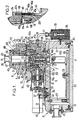
- the device comprises three main parts, namely: a part A essentially comprising the measuring element with a piston 1 and a cylinder 2; a part B constituting an electromagnetic balance with a part 3 intended to receive the force to be measured; and a connecting part C transmitting the force of the piston 1 of the assembly A to the part 3 of the balance B.
- Part A firstly comprises, as indicated above, a vertical cylinder 2 and a piston 1 sliding in the cylinder 2, the assembly of which constitutes the actual measuring element, ensuring the transformation of a pressure or of a pressure difference in a force, force transmitted by part C to the electromagnetic balance B.
- the electromagnetic balance is constituted by an electromagnetic re-balancing dynamometer, for example of the digital or digital type, providing a quantity proportional to the force transmitted by the piston 1, with digital display allowing direct and immediate reading and / or transmission by a interface to a computer.
- FIG. 1 is shown schematically the coil of the dynamometer designated under the reference 4.
- connection in translation, along a vertical axis XX, of the part 3 of the dynamometer (part B) with the piston 1 (of the part A) is provided by a connecting rod 5 housed in a coupling block 6; an O-ring 7, sandwiched between the connecting rod 5 and a socket 5b, provides a flexible connection between the connecting rod 5 and the block 6, while allowing a slight angular movement of the connecting rod in this block.
- the lower end of the coupling block 6 is provided with a conical recess of axis XX (the narrowed part of the truncated cone being directed upwards) into which enters a frustoconical part 8 forming connecting part C and terminated by a threaded rod 9 screwed into part 3 of the dynamometer.
- the upper part of the coupling block 6 cooperates with the head 6a of the piston 1 in which is provided a housing 10 followed by a recess 10a which encloses the lower end of the piston 1.
- a ball 11 of tungsten carbide is in contact with the upper end of the rod 5a of the connecting rod 5, but not with the piston 1.
- This ball 11 is disposed between an upper ball stop 12a, which separates it from the piston 1 and which is mounted free radially so as to center on the ball 1, and a lower ball bearing 12b which centers the ball 11 relative to the axis of the piston 1.
- Such an arrangement ensures the transmission of forces, even significant, between piston 1 and connecting rod 5 without risk of deterioration, or of induction of axial noise.
- a washer 13 retains the ball stop 12a in the piston head 6a, while the ball bearing 12b centers the ball 11 relative to the piston head 6a.
- This bearing 12b except its inner ring, is movable in rotation, with the piston head 6a and the piston 1 itself, around the inner ring of this bearing which is itself fixed in rotation, as is the ball 11 that this inner ring surrounds.
- the piston 1 turns freely while ensuring the transmission of the forces in vertical translation to the connecting rod 5 first and, through it, from the frustoconical part 8 and the threaded rod 9 to the part 3 of the dynamometer.
- each finger 15a, 15b is equipped with a bearing 16a, 16b , each finger, integral in rotation, about the axis XX, with the piston head 6a, capable of sliding freely in a housing 17 formed in a pulley 18; this sliding ensures freedom of movement in translation of the fingers 15 along the axis XX of the piston 1.
- the pulley 18 on which is fixed a toothed ring 19, is bored to receive an inner ring 18a, the play between the parts 18 and 18a being sufficient to allow the radial displacement of the crown 18a relative to its housing; four springs 18b, arranged in a cross, keep the crown 18a centered in the pulley 18.
- Each spring 18b is positioned, on the side of the pulley 18, on a stud 18c and is centered, on the side of the crown 18a, in the bore made in a screw 18d which allows the adjustment of the spring preload.
- the crown 18a rests on four pads 18th (made of polytetrafluoroethylene for example).
- Two shouldered screws 18f define the axial functional clearance between the crown 18a and the pulley 18, without hampering the relative radial displacement of the two parts.
- An 18g polyfluorethylene washer is placed under the head of each 18f screw.
- the system thus defined ensures a symmetrical double contact between the inner ring 18a and the piston head 6a, independently of the machining dispersions.
- the washers 18g and the pads 18e limit the contact friction between the crown 18a and the pulley 18.
- the tilting torque applied by the fingers 15a, 15b for rotation is canceled, or at least limited.
- connection rod 5 to exert the force, which reaches it from the piston 1, on a bush 5b guided by a double bore. in the coupling block 6.
- a washer 5c stopped by a circlip 5d, limits the upward translation of the sleeve 5b and the connecting rod 5.
- a spring 5e, surrounding the socket 5b, is supported, at one end, on the coupling block 6 and, at the other end, on a shoulder of the socket 5b. It prohibits the translation of the latter downward for a force defined by the stiffness and the pre-stress of the spring 5e.
- the sleeve compresses the spring 5e.
- the bearings of the drive fingers 15a, 15b abut on the pulley 18.
- the ring gear 19 meshes with a bevel gear 20 driven in rotation from an electric motor 21, a reduction in the speed of rotation of the motor 21 being transmitted by the assembly 20-19 to the pulley 18 and therefore to the piston 1
- Two bearings 18 1 , 18 2 are provided to ensure easy rotation of the pulley 18.
- the structure which has just been described compensates for any misalignment between the part 3 of the dynamometer and the piston 1 for measuring the pressure while ensuring the rotation of this piston at a rotation speed lower than that of the engine. 21; such a structure further isolates the piston 1 from the effects, in particular vibrations, generated by the moving parts.
- the part 3 the coupling block 6, the connecting rod 5, the ball 11 and the inner ring of the bearing 12b (ring which guides the ball) constitute the fixed parts in rotation, but movable in vertical translation, of the assembly parts transmitting the force of the piston to the dynamometer; on the other hand the piston 1, its head 6a and the bearing 12b, with the exception of its inner ring, constitute the mobile parts in rotation of this assembly transmitting the force of the piston to the coil.
- the pressure to be measured (absolute pressure by relative to vacuum or relative pressure) is applied to the upper enclosure 22 above the upper face 23 of the piston 1, a flange 24 allowing connection with the pressure source to be measured.
- the lower enclosure defined below, into which the lower part of the piston 1 plunges with its lower face 25, receives the reference pressure which can be either vacuum, or atmospheric pressure, or a second pressure in the case where the 'We want to measure the difference between the pressures applied on the upper face 23 and on the lower face 25 of the piston 1.
- the lower enclosure which must be able to be evacuated or under a desired well-determined pressure is sealed.
- the assembly 3-4 is mounted "in the air" on a base plate 28 fixed by three columns 29 (arranged in a triangle) to the main body 27.
- a bottom 30 comes to close the main body 27, an O-ring 31 ensuring the seal between the main body 27 and the bottom 30; Likewise an O-ring 32 seals between the intermediate body 26 and the main body 27.
- the removable mounting of the bottom 30 allows good accessibility to the dynamometer coil, an adjustment screw 33 ensuring the fixing in correct position of the coil 4 on plate 28.
- the electrical connection between the coil 4 of the dyna-meter and the electronics of the dynamometer is ensured by means of a glass cup 34 crossed by pins 35 on which the connecting wires 36 and 37 are fixed between the coil of the dynamometer and the electronics of it.
- a flange 38 covers the glass dish 34, an O-ring 39 sealing the passage of the electrical connections which finally come out in the form of a layer of wires 40.
- the external electric motor 21 drives the toothed pinion 20 by means of a magnetic coupling 41 having a purely radial magnetization effect therefore not causing any axial reaction on said pinion, which limits friction losses; the magnetic coupling also performs the function of the torque limiter and therefore of protection of the electric motor 21 in the event of overload.
- the magnetic coupling 41 is housed in a housing 42, an O-ring 43 ensuring sealing between the housing 42 and the intermediate body 26.
- the volume of the lower enclosure in rooms 26 and 27 has been reduced to a minimum; it is essentially constituted by spaces 44a, 44b, 44c and 44d. This facilitates the vacuuming of the reference enclosure when it is desired to carry out absolute pressure measurements.
- all the screws and the columns are drilled which, if they trapped gas, slowed down the evacuation of the lower enclosure.
- the O-rings ensuring the sealing of the enclosure they are coated with a silicone grease which, by perfecting the sealing, exhibits excellent behavior under vacuum due to its low vapor pressure.
- connection of the lower enclosure 22a, 44a-44d is done by means of two flanges, of which only one 45 is visible in FIG. 1, this flange 45, fixed on the main body 27, exiting towards the exterior and being intended for connection to a vacuum pump, to atmospheric pressure or to a pressure with respect to which it is desired to measure a pressure applied by the upper flange 24, while the other flange 45 (shown in FIG. 30 is connected to a vacuum gauge, the indications of which are displayed by a vacuum indicator visible on the front face of the housing (see below, with reference to Figure 3).
- piston-cylinder assemblies are preferably made of tungsten carbide.
- piston-cylinder clearances are provided, these clearances being differentiated between them by the value of the piston cross-section and therefore the bore of the cylinder.
- These piston-cylinder assemblies define pressure ranges of different ranges, the increase in the pressure range naturally leading to a decrease in the sensitivity of the digital display of the pressure or pressure difference measured. Against by the external dimensions of the cylinder of the different games are identical, which allows the exchangeability of the different games in the part 2a of the device which receives the cylinder.
- the change of a piston-cylinder assembly can be carried out without having to disassemble the two parts of this assembly, which is very advantageous, because otherwise their cleaning would pose difficult problems.
- This assembly is therefore unitary and the cylinder 2 is held in its housing in the part 2a by means of two lower flanges 46 and upper 47 fixed by captive screws 48. These flanges each include an O-ring 46a, 47a.
- the upper flange 47 which comprises the connection 24 is preferably made of stainless steel in order to withstand the numerous stresses to which it is subjected.
- the temperature of the measurement is advantageously taken into account, since a variation in temperature more or less expands the piston-cylinder assembly, which modifies the value of the actual effective cross-section of the piston.
- the temperature is measured by means of a temperature probe 49 (FIG. 2) which is as close as possible to the assembly of the 1-cylinder piston 2, without being integral with this assembly.
- the probe 49 is introduced into a copper tip 49a, itself fitted into a tube 49b.
- a heat-shrinkable sheath 49c protects the probe wires and encloses the free end of the tube 49b.
- the assembly is mounted glued in a support bar 49d which allows, by captive screws, a mounting in the air under the flange 49e of the intermediate body 46. A light allows the exit of the probe.
- This temperature probe 49 makes it possible to correct the pressure value by calculation using a computer which receives on the one hand the digital measurements of the dynamometer using the interface mentioned above, and on the other hand by another interface. (possibly integrated into the first interface) the digital indications of a digital voltmeter, not shown, connected by a cable 50 to the temperature probe 49.
- the computer therefore therefore gives at all times the digital value corrected for the relative or differential absolute pressure that l 'we want to measure.
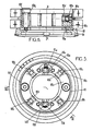
- FIG. 3 we will describe the general assembly of the device which has just been described with reference to FIGS. 1 and 2.
- the device is suspended in a casing 52 by three screws, the vibration isolation being ensured by a washer made of an insulating material from the vibration point of view, for example in "Klingerit” disposed between the intermediate body 26 and the casing 52, thus only by three shouldered rings, for example in “Rylsan”, mounted on the three fixing screws.
- the vacuum gauge is illustrated at 53 and is connected directly to the flange 45a (which is carried like the flange 45 by the main body 27).
- a control plate 54 is carried by the inclined front face 55 of the housing 52.
- the control plate 54 carries a vacuum indicator 56 with a dial 56a on the one hand, and a series of switches and indicators on the other go; it is a light 58 and a switch 59 for controlling the start-up of the device, a light 60 and a switch 61 for controlling the power on of the indicator vacuum 56 and finally a switch 62 to trigger the reset of the display, this switch being used during the taring of the device.
- the rear face 63 of the device comprises a closure plate which snaps onto the housing itself 52; this closing plate frames a bracket carrying the electrical connections, namely the output 50a for reading the temperature probe and for reading the residual pressure, a fuse 64 for protecting the electrical system of the device, an output 65 for the connection to the mains and finally a dual interface 66 allowing the connection of the device with a computer determining the value of the pressure corrected for the influence of the temperature digitally displayed in window 57.
- a printed circuit placed under the main body, provides the connection between the various electrical elements.
- Four clamping screws 67 allow the verticality of the piston axis to be adjusted, based on the indications of a spirit level 68 placed on the top of the device.
- Two handles 52a allow the grip. They are placed so that the mass of the device is evenly distributed.
- the piston 1 which is movable in translation vertically (along the axis XX) in the bore of cylinder 2 and which is driven in rotation about its axis XX by the motor 21, is subjected on its two faces, upper 23 and lower 25, to the pressures which prevail respectively in the upper enclosure 22 and in the lower enclosure 44a, 44b, 44c, 44d.
- the pressure prevailing in the enclosure 22 is the pressure which must be measured either absolutely when the vacuum prevails in the lower enclosure, or in a relative manner when the atmospheric pressure prevails in the lower enclosure; in addition, it is also possible to measure a pressure difference, namely between the pressure of a first fluid arriving in the enclosure 22 by the flange 24 and that of a second fluid arriving in the lower enclosure 44a-44d by the flange 45.
- the pressure (zero, atmospheric or of a second fluid) prevailing in the lower enclosure 44a-44d will henceforth be called reference pressure P i
- the pressure prevailing in the enclosure 22 will be called the pressure to be measured P 2
- the measurement enclosure will be called enclosure 22 and the reference enclosure enclosure 44a-44d.
- the bore of the cylinder 2 has a circular groove 69 for example halfway up the cylinder 2, as well as an annular groove 71 in the part 2a at the same level as the groove 69.
- These two grooves communicate by one or more (in particular two) channels 70 drilled in the cylinder 2.
- Channels 72 and 73 perpendicular to each other, bring the annular groove 71 - and therefore the annular groove 69 (due to the channels 70) into communication - with a threaded outlet 74 formed in the intermediate body 26.
- a glued plug 75 is provided for for possible cleaning, while an O-ring 76 seals the channel 73 when the part 2a passes to the intermediate body 26.
- a flexible tube 77 is fixed to the outlet 74; this flexible tube 77 ends in a filter 78 which plunges into a bottle 79 containing crystals of a desiccant.
- the bottle 79 is fixed by bolts 80 to the main body 27 and has orifices for the admission of atmospheric air.
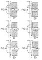
- the flow in this clearance is proportional to the difference between the pressure of the gas in the groove 69, namely the atmospheric pressure P a and that of the upper or lower end concerned.
- Q 1 the flow in the lower part of the game and Q 2 the flow in the upper part of the game, that is to say respectively below and above the groove 69 and each channel 70
- Q 1 is proportional to P i - P a
- Q is proportional to P 2 - Pa
- P 1 and P 2 can be larger or smaller than atmospheric pressure P a .
- This figure concerns the calibration of the dynamometer for which the measurement enclosure 22 and the reference enclosure 44a-44d are both at zero pressure by being connected together and placed under vacuum.
- the flow rate Q z in the case of FIG. 4B, decreases with respect to the flow rate Q 2 , in the case of FIG. 4A, in proportion to the difference between the pressure P 2 and the zero pressure.
- the flow rate Q 1 it remains unchanged compared to the flow rate Q 1 of FIGS. 4A and 4B, since P a and P 1 have not changed.
- the pressure difference at which the upper half-clearance is subjected is equal to atmospheric pressure and therefore the flow Q 2 is equal to the flow Q 1 .
- the feed rate is zero in each channel 70.
- the pressure P 2 continuing to increase is now greater than twice the atmospheric pressure.
- the disturbance created by this flow at the reference pressure is constant. It can be determined and can be taken into account.
- the measurement pressure P 2 is greater than several times the atmospheric pressure, for example more than ten times greater than the atmospheric pressure, it is advantageous to carry out a relative measurement (with respect to the atmospheric pressure) and to determine the exact value of this atmospheric pressure.
Landscapes
- Chemical & Material Sciences (AREA)
- Analytical Chemistry (AREA)
- Physics & Mathematics (AREA)
- General Physics & Mathematics (AREA)
- Measuring Fluid Pressure (AREA)
Priority Applications (1)
| Application Number | Priority Date | Filing Date | Title |
|---|---|---|---|
| AT86400778T ATE44616T1 (de) | 1985-04-22 | 1986-04-11 | Vorrichtung mit kolben fuer die sehr genaue messung von fluidumdrucken. |
Applications Claiming Priority (2)
| Application Number | Priority Date | Filing Date | Title |
|---|---|---|---|
| FR8506063 | 1985-04-22 | ||
| FR8506063A FR2580807B1 (fr) | 1985-04-22 | 1985-04-22 | Perfectionnements aux dispositifs pour la mesure tres precise des pressions de fluide |
Publications (2)
| Publication Number | Publication Date |
|---|---|
| EP0202970A1 EP0202970A1 (fr) | 1986-11-26 |
| EP0202970B1 true EP0202970B1 (fr) | 1989-07-12 |
Family
ID=9318501
Family Applications (1)
| Application Number | Title | Priority Date | Filing Date |
|---|---|---|---|
| EP86400778A Expired EP0202970B1 (fr) | 1985-04-22 | 1986-04-11 | Dispositif à piston pour la mesure très précise des pressions de fluide |
Country Status (6)
| Country | Link |
|---|---|
| US (1) | US4669317A (OSRAM) |
| EP (1) | EP0202970B1 (OSRAM) |
| JP (1) | JPS61292031A (OSRAM) |
| AT (1) | ATE44616T1 (OSRAM) |
| DE (1) | DE3664383D1 (OSRAM) |
| FR (1) | FR2580807B1 (OSRAM) |
Families Citing this family (4)
| Publication number | Priority date | Publication date | Assignee | Title |
|---|---|---|---|---|
| GB8616157D0 (en) * | 1986-07-02 | 1986-08-06 | Furness Controls Ltd | Calibrated gas pressure |
| US5257640A (en) * | 1991-10-18 | 1993-11-02 | Delajoud Pierre R | Fine pressure control system for high pressure gas |
| US5325707A (en) * | 1993-03-08 | 1994-07-05 | Slater Harry F | Air filter condition indicator |
| JP3498665B2 (ja) * | 1999-03-12 | 2004-02-16 | 株式会社デンソー | 圧力検出装置およびその製造方法 |
Family Cites Families (7)
| Publication number | Priority date | Publication date | Assignee | Title |
|---|---|---|---|---|
| JPS5319231B2 (OSRAM) * | 1972-11-28 | 1978-06-20 | ||
| JPS54163980U (OSRAM) * | 1978-05-10 | 1979-11-16 | ||
| FR2481801A1 (fr) * | 1980-04-30 | 1981-11-06 | Delajoud Pierre | Dispositif pour la mesure tres precise des pressions de fluide avec affichage de la pression mesuree |
| US4491016A (en) * | 1981-11-05 | 1985-01-01 | Pfister Gmbh | Method and apparatus for measuring the pressure of a fluid |
| DE3143919A1 (de) * | 1981-11-05 | 1983-05-11 | Pfister Gmbh, 8900 Augsburg | Verfahren und vorrichtung zum messen eines druckes, insbesondere eines fuids |
| CA1201608A (en) * | 1982-11-22 | 1986-03-11 | Yoshiteru Sonoda | Precision pressure gauge |
| DE3302175A1 (de) * | 1983-01-24 | 1984-07-26 | Pfister Gmbh, 8900 Augsburg | Verfahren und vorrichtung zum messen eines druckes, insbesondere einer fluessigkeit |
-
1985
- 1985-04-22 FR FR8506063A patent/FR2580807B1/fr not_active Expired
-
1986
- 1986-04-11 DE DE8686400778T patent/DE3664383D1/de not_active Expired
- 1986-04-11 EP EP86400778A patent/EP0202970B1/fr not_active Expired
- 1986-04-11 AT AT86400778T patent/ATE44616T1/de not_active IP Right Cessation
- 1986-04-17 US US06/853,031 patent/US4669317A/en not_active Expired - Lifetime
- 1986-04-22 JP JP61091414A patent/JPS61292031A/ja active Granted
Also Published As
| Publication number | Publication date |
|---|---|
| FR2580807A1 (fr) | 1986-10-24 |
| JPS61292031A (ja) | 1986-12-22 |
| DE3664383D1 (en) | 1989-08-17 |
| EP0202970A1 (fr) | 1986-11-26 |
| US4669317A (en) | 1987-06-02 |
| ATE44616T1 (de) | 1989-07-15 |
| JPH0529051B2 (OSRAM) | 1993-04-28 |
| FR2580807B1 (fr) | 1987-12-24 |
Similar Documents
| Publication | Publication Date | Title |
|---|---|---|
| FR2580401A1 (fr) | Appareil et procede pour mesurer les proprietes visco-elastiques de materiaux | |
| FR2563906A1 (fr) | Dispositif de controle du fonctionnement d'une installation de pompage de puits et dispositif de detection de variations du mouvement d'une piece | |
| FR2587114A1 (fr) | Viscosimetre perfectionne destine notamment a la mesure de viscosite des huiles minerales | |
| EP0202970B1 (fr) | Dispositif à piston pour la mesure très précise des pressions de fluide | |
| EP0847520B1 (fr) | Dispositif de mesure de couple de torsion d'un arbre tournant | |
| EP0579961B1 (fr) | Appareil de mesure de grandeurs linéaires | |
| EP0039293B1 (fr) | Dispositif pour la mesure très précise des pressions de fluide avec affichage de la pression mesurée | |
| EP0032098A1 (fr) | Dispositif de prélèvement et de distribution de volumes réglables de liquides, à affichage numérique | |
| LU84283A1 (fr) | Capteur de pression differentielle | |
| FR2459462A1 (fr) | Dynanometre a diaphragmes | |
| FR2515822A1 (fr) | Appareil d'essais dynamiques de torsion, notamment pour arbres et essieux | |
| FR2580402A1 (fr) | Permeametre | |
| EP0208820A1 (fr) | Manomètre à capsule fermée par une membrane élastique | |
| FR2695794A1 (fr) | Transmission pour l'entraînement d'appareils agricoles ou dans de tels appareils. | |
| FR2500623A1 (fr) | Debitmetre a vortex a detection exterieure | |
| EP0237386A1 (fr) | Dispositif de transmission à deux degrés de liberté en entrée et un seul en sortie | |
| EP1554554B1 (fr) | Capteur de pression a reseau de bragg. | |
| FR2754342A1 (fr) | Cellule de conversion d'une pression differentielle en signal electrique | |
| EP0517592A1 (fr) | Procédé et dispositif d'étalonnage de couplemètre et couplemètre compact adapté au dispositif | |
| EP3306420B1 (fr) | Pièce d'horlogerie comportant un capteur de pression | |
| EP0320387B1 (fr) | Capteur de mesure de pressions élevées à grande distance | |
| EP0194188B1 (fr) | Capteur de pression à membrane comportant des moyens de compensation en température | |
| FR2685774A1 (fr) | Tribometre bidisque permettant notamment des vitesses elevees en environnements extremes. | |
| FR2652646A1 (fr) | Installation pour la mesure du niveau ou de la densite d'un liquide. | |
| EP0039255A1 (fr) | Capteur de pression pour organe rotatif |
Legal Events
| Date | Code | Title | Description |
|---|---|---|---|
| PUAI | Public reference made under article 153(3) epc to a published international application that has entered the european phase |
Free format text: ORIGINAL CODE: 0009012 |
|
| AK | Designated contracting states |
Kind code of ref document: A1 Designated state(s): AT BE CH DE GB IT LI LU NL SE |
|
| 17P | Request for examination filed |
Effective date: 19870515 |
|
| 17Q | First examination report despatched |
Effective date: 19880921 |
|
| RAP3 | Party data changed (applicant data changed or rights of an application transferred) |
Owner name: DESGRANGES & HUOT Owner name: DELAJOUD, PIERRE |
|
| GRAA | (expected) grant |
Free format text: ORIGINAL CODE: 0009210 |
|
| AK | Designated contracting states |
Kind code of ref document: B1 Designated state(s): AT BE CH DE GB IT LI LU NL SE |
|
| PG25 | Lapsed in a contracting state [announced via postgrant information from national office to epo] |
Ref country code: NL Effective date: 19890712 Ref country code: AT Effective date: 19890712 |
|
| REF | Corresponds to: |
Ref document number: 44616 Country of ref document: AT Date of ref document: 19890715 Kind code of ref document: T |
|
| REF | Corresponds to: |
Ref document number: 3664383 Country of ref document: DE Date of ref document: 19890817 |
|
| ITF | It: translation for a ep patent filed | ||
| GBT | Gb: translation of ep patent filed (gb section 77(6)(a)/1977) | ||
| NLV1 | Nl: lapsed or annulled due to failure to fulfill the requirements of art. 29p and 29m of the patents act | ||
| PG25 | Lapsed in a contracting state [announced via postgrant information from national office to epo] |
Ref country code: SE Effective date: 19900201 |
|
| PG25 | Lapsed in a contracting state [announced via postgrant information from national office to epo] |
Ref country code: LU Free format text: LAPSE BECAUSE OF NON-PAYMENT OF DUE FEES Effective date: 19900430 Ref country code: BE Effective date: 19900430 |
|
| PLBE | No opposition filed within time limit |
Free format text: ORIGINAL CODE: 0009261 |
|
| STAA | Information on the status of an ep patent application or granted ep patent |
Free format text: STATUS: NO OPPOSITION FILED WITHIN TIME LIMIT |
|
| 26N | No opposition filed | ||
| BERE | Be: lapsed |
Owner name: DESGRANGES & HUOT Effective date: 19900430 Owner name: DELAJOUD PIERRE Effective date: 19900430 |
|
| REG | Reference to a national code |
Ref country code: CH Ref legal event code: PUE Owner name: DESGRANGES & HUOT |
|
| REG | Reference to a national code |
Ref country code: GB Ref legal event code: 732E |
|
| ITTA | It: last paid annual fee | ||
| ITPR | It: changes in ownership of a european patent |
Owner name: CESSIONE;DESGRANGES & HUOT |
|
| PGFP | Annual fee paid to national office [announced via postgrant information from national office to epo] |
Ref country code: CH Payment date: 20010329 Year of fee payment: 16 |
|
| PGFP | Annual fee paid to national office [announced via postgrant information from national office to epo] |
Ref country code: GB Payment date: 20010330 Year of fee payment: 16 |
|
| PGFP | Annual fee paid to national office [announced via postgrant information from national office to epo] |
Ref country code: DE Payment date: 20010406 Year of fee payment: 16 |
|
| REG | Reference to a national code |
Ref country code: GB Ref legal event code: IF02 |
|
| PG25 | Lapsed in a contracting state [announced via postgrant information from national office to epo] |
Ref country code: GB Free format text: LAPSE BECAUSE OF NON-PAYMENT OF DUE FEES Effective date: 20020411 |
|
| PG25 | Lapsed in a contracting state [announced via postgrant information from national office to epo] |
Ref country code: LI Free format text: LAPSE BECAUSE OF NON-PAYMENT OF DUE FEES Effective date: 20020430 Ref country code: CH Free format text: LAPSE BECAUSE OF NON-PAYMENT OF DUE FEES Effective date: 20020430 |
|
| PG25 | Lapsed in a contracting state [announced via postgrant information from national office to epo] |
Ref country code: DE Free format text: LAPSE BECAUSE OF NON-PAYMENT OF DUE FEES Effective date: 20021101 |
|
| GBPC | Gb: european patent ceased through non-payment of renewal fee |
Effective date: 20020411 |
|
| REG | Reference to a national code |
Ref country code: CH Ref legal event code: PL |
|
| PG25 | Lapsed in a contracting state [announced via postgrant information from national office to epo] |
Ref country code: IT Free format text: LAPSE BECAUSE OF NON-PAYMENT OF DUE FEES;WARNING: LAPSES OF ITALIAN PATENTS WITH EFFECTIVE DATE BEFORE 2007 MAY HAVE OCCURRED AT ANY TIME BEFORE 2007. THE CORRECT EFFECTIVE DATE MAY BE DIFFERENT FROM THE ONE RECORDED. Effective date: 20050411 |