EP0202843A2 - Air separation method and apparatus - Google Patents
Air separation method and apparatus Download PDFInfo
- Publication number
- EP0202843A2 EP0202843A2 EP86303609A EP86303609A EP0202843A2 EP 0202843 A2 EP0202843 A2 EP 0202843A2 EP 86303609 A EP86303609 A EP 86303609A EP 86303609 A EP86303609 A EP 86303609A EP 0202843 A2 EP0202843 A2 EP 0202843A2
- Authority
- EP
- European Patent Office
- Prior art keywords
- nitrogen
- enriched
- column
- liquid
- stream
- Prior art date
- Legal status (The legal status is an assumption and is not a legal conclusion. Google has not performed a legal analysis and makes no representation as to the accuracy of the status listed.)
- Granted
Links
- 238000000926 separation method Methods 0.000 title description 9
- IJGRMHOSHXDMSA-UHFFFAOYSA-N Atomic nitrogen Chemical compound N#N IJGRMHOSHXDMSA-UHFFFAOYSA-N 0.000 claims abstract description 104
- 229910052757 nitrogen Inorganic materials 0.000 claims abstract description 52
- XKRFYHLGVUSROY-UHFFFAOYSA-N Argon Chemical compound [Ar] XKRFYHLGVUSROY-UHFFFAOYSA-N 0.000 claims abstract description 34
- 238000004821 distillation Methods 0.000 claims abstract description 27
- QVGXLLKOCUKJST-UHFFFAOYSA-N atomic oxygen Chemical compound [O] QVGXLLKOCUKJST-UHFFFAOYSA-N 0.000 claims abstract description 19
- 239000001301 oxygen Substances 0.000 claims abstract description 19
- 229910052760 oxygen Inorganic materials 0.000 claims abstract description 19
- 229910052786 argon Inorganic materials 0.000 claims abstract description 17
- 238000002156 mixing Methods 0.000 claims abstract description 10
- 239000000203 mixture Substances 0.000 claims abstract description 10
- 238000010992 reflux Methods 0.000 claims abstract description 10
- 239000007788 liquid Substances 0.000 claims description 35
- 238000000034 method Methods 0.000 claims description 12
- 238000005057 refrigeration Methods 0.000 claims description 8
- 239000011369 resultant mixture Substances 0.000 claims description 5
- 238000011144 upstream manufacturing Methods 0.000 claims description 4
- 239000002826 coolant Substances 0.000 claims description 3
- MYMOFIZGZYHOMD-UHFFFAOYSA-N Dioxygen Chemical compound O=O MYMOFIZGZYHOMD-UHFFFAOYSA-N 0.000 abstract description 5
- 238000001816 cooling Methods 0.000 description 4
- 230000000694 effects Effects 0.000 description 3
- 238000004508 fractional distillation Methods 0.000 description 3
- CURLTUGMZLYLDI-UHFFFAOYSA-N Carbon dioxide Chemical compound O=C=O CURLTUGMZLYLDI-UHFFFAOYSA-N 0.000 description 2
- 239000007789 gas Substances 0.000 description 2
- 238000010438 heat treatment Methods 0.000 description 2
- 239000012071 phase Substances 0.000 description 2
- 238000005086 pumping Methods 0.000 description 2
- OLBVUFHMDRJKTK-UHFFFAOYSA-N [N].[O] Chemical compound [N].[O] OLBVUFHMDRJKTK-UHFFFAOYSA-N 0.000 description 1
- 230000005587 bubbling Effects 0.000 description 1
- 229910002092 carbon dioxide Inorganic materials 0.000 description 1
- 239000001569 carbon dioxide Substances 0.000 description 1
- 238000010586 diagram Methods 0.000 description 1
- 239000012530 fluid Substances 0.000 description 1
- 238000005194 fractionation Methods 0.000 description 1
- 229930195733 hydrocarbon Natural products 0.000 description 1
- 150000002430 hydrocarbons Chemical class 0.000 description 1
- 239000007791 liquid phase Substances 0.000 description 1
- 238000000746 purification Methods 0.000 description 1
- XLYOFNOQVPJJNP-UHFFFAOYSA-N water Substances O XLYOFNOQVPJJNP-UHFFFAOYSA-N 0.000 description 1
Images
Classifications
-
- F—MECHANICAL ENGINEERING; LIGHTING; HEATING; WEAPONS; BLASTING
- F25—REFRIGERATION OR COOLING; COMBINED HEATING AND REFRIGERATION SYSTEMS; HEAT PUMP SYSTEMS; MANUFACTURE OR STORAGE OF ICE; LIQUEFACTION SOLIDIFICATION OF GASES
- F25J—LIQUEFACTION, SOLIDIFICATION OR SEPARATION OF GASES OR GASEOUS OR LIQUEFIED GASEOUS MIXTURES BY PRESSURE AND COLD TREATMENT OR BY BRINGING THEM INTO THE SUPERCRITICAL STATE
- F25J3/00—Processes or apparatus for separating the constituents of gaseous or liquefied gaseous mixtures involving the use of liquefaction or solidification
- F25J3/02—Processes or apparatus for separating the constituents of gaseous or liquefied gaseous mixtures involving the use of liquefaction or solidification by rectification, i.e. by continuous interchange of heat and material between a vapour stream and a liquid stream
- F25J3/04—Processes or apparatus for separating the constituents of gaseous or liquefied gaseous mixtures involving the use of liquefaction or solidification by rectification, i.e. by continuous interchange of heat and material between a vapour stream and a liquid stream for air
- F25J3/0446—Processes or apparatus for separating the constituents of gaseous or liquefied gaseous mixtures involving the use of liquefaction or solidification by rectification, i.e. by continuous interchange of heat and material between a vapour stream and a liquid stream for air using the heat generated by mixing two different phases
-
- F—MECHANICAL ENGINEERING; LIGHTING; HEATING; WEAPONS; BLASTING
- F25—REFRIGERATION OR COOLING; COMBINED HEATING AND REFRIGERATION SYSTEMS; HEAT PUMP SYSTEMS; MANUFACTURE OR STORAGE OF ICE; LIQUEFACTION SOLIDIFICATION OF GASES
- F25J—LIQUEFACTION, SOLIDIFICATION OR SEPARATION OF GASES OR GASEOUS OR LIQUEFIED GASEOUS MIXTURES BY PRESSURE AND COLD TREATMENT OR BY BRINGING THEM INTO THE SUPERCRITICAL STATE
- F25J3/00—Processes or apparatus for separating the constituents of gaseous or liquefied gaseous mixtures involving the use of liquefaction or solidification
- F25J3/02—Processes or apparatus for separating the constituents of gaseous or liquefied gaseous mixtures involving the use of liquefaction or solidification by rectification, i.e. by continuous interchange of heat and material between a vapour stream and a liquid stream
- F25J3/04—Processes or apparatus for separating the constituents of gaseous or liquefied gaseous mixtures involving the use of liquefaction or solidification by rectification, i.e. by continuous interchange of heat and material between a vapour stream and a liquid stream for air
- F25J3/04642—Recovering noble gases from air
- F25J3/04648—Recovering noble gases from air argon
- F25J3/04654—Producing crude argon in a crude argon column
- F25J3/0466—Producing crude argon in a crude argon column as a parallel working rectification column or auxiliary column system in a single pressure main column system
-
- F—MECHANICAL ENGINEERING; LIGHTING; HEATING; WEAPONS; BLASTING
- F25—REFRIGERATION OR COOLING; COMBINED HEATING AND REFRIGERATION SYSTEMS; HEAT PUMP SYSTEMS; MANUFACTURE OR STORAGE OF ICE; LIQUEFACTION SOLIDIFICATION OF GASES
- F25J—LIQUEFACTION, SOLIDIFICATION OR SEPARATION OF GASES OR GASEOUS OR LIQUEFIED GASEOUS MIXTURES BY PRESSURE AND COLD TREATMENT OR BY BRINGING THEM INTO THE SUPERCRITICAL STATE
- F25J2200/00—Processes or apparatus using separation by rectification
- F25J2200/02—Processes or apparatus using separation by rectification in a single pressure main column system
-
- F—MECHANICAL ENGINEERING; LIGHTING; HEATING; WEAPONS; BLASTING
- F25—REFRIGERATION OR COOLING; COMBINED HEATING AND REFRIGERATION SYSTEMS; HEAT PUMP SYSTEMS; MANUFACTURE OR STORAGE OF ICE; LIQUEFACTION SOLIDIFICATION OF GASES
- F25J—LIQUEFACTION, SOLIDIFICATION OR SEPARATION OF GASES OR GASEOUS OR LIQUEFIED GASEOUS MIXTURES BY PRESSURE AND COLD TREATMENT OR BY BRINGING THEM INTO THE SUPERCRITICAL STATE
- F25J2200/00—Processes or apparatus using separation by rectification
- F25J2200/50—Processes or apparatus using separation by rectification using multiple (re-)boiler-condensers at different heights of the column
-
- F—MECHANICAL ENGINEERING; LIGHTING; HEATING; WEAPONS; BLASTING
- F25—REFRIGERATION OR COOLING; COMBINED HEATING AND REFRIGERATION SYSTEMS; HEAT PUMP SYSTEMS; MANUFACTURE OR STORAGE OF ICE; LIQUEFACTION SOLIDIFICATION OF GASES
- F25J—LIQUEFACTION, SOLIDIFICATION OR SEPARATION OF GASES OR GASEOUS OR LIQUEFIED GASEOUS MIXTURES BY PRESSURE AND COLD TREATMENT OR BY BRINGING THEM INTO THE SUPERCRITICAL STATE
- F25J2205/00—Processes or apparatus using other separation and/or other processing means
- F25J2205/90—Mixing of components
-
- F—MECHANICAL ENGINEERING; LIGHTING; HEATING; WEAPONS; BLASTING
- F25—REFRIGERATION OR COOLING; COMBINED HEATING AND REFRIGERATION SYSTEMS; HEAT PUMP SYSTEMS; MANUFACTURE OR STORAGE OF ICE; LIQUEFACTION SOLIDIFICATION OF GASES
- F25J—LIQUEFACTION, SOLIDIFICATION OR SEPARATION OF GASES OR GASEOUS OR LIQUEFIED GASEOUS MIXTURES BY PRESSURE AND COLD TREATMENT OR BY BRINGING THEM INTO THE SUPERCRITICAL STATE
- F25J2250/00—Details related to the use of reboiler-condensers
- F25J2250/20—Boiler-condenser with multiple exchanger cores in parallel or with multiple re-boiling or condensing streams
Abstract
Description
- This invention relates to a method and apparatus for the separation of air.
- It is particularly concerned with the separation by fractional distillation of one or both of a nitrogen product and an argon product from air.
- It is well known that by purifying and liquefying air and then subjecting the resulting liquid to fractional distillation, relatively pure oxygen and nitrogen fractions can be obtained. Moreover, in one intermediate region in the distillation system the concentration of argon in the vapour phase will be greater than its concentration in the incoming air for separation. Accordingly, it is also well known that an argon-rich product can be formed by subjecting the argon-enriched vapour to further fractionation in a separate column.
- In order to enable the fractional distillation to take place, it is necessary to provide refrigeration to the distillation system. Moreover, if nitrogen is required as a product in the liquid phase it is necessary to provide refrigeration in order to liquefy the nitrogen.
- When the vapour of a first component at a cryogenic temperature is mixed with the liquid of a second less volatile component at a cryogenic temperature, a net cooling effect is produced. Although this phenomenon has been observed previously, there has been no appreciation in the art that the phenomenon may be used with advantage in cryogenic air separation.
- According to the present invention, there is provided a method of separating air including the steps of separating air in a distillation zone into an oxygen-enriched liquid fraction and a nitrogen-enriched vapour fraction, taking a first stream from said nitrogen-enriched vapour fraction and mixing it with a stream of oxygen-enriched liquid taken from said liquid fraction, and employing at least a part of the resultant mixture to perform a refrigeration duty.
- The invention also provides apparatus for separating air, including a distillation system having an inlet for air, liquid-vapour means adapted to separate the air into an oxygen-enriched liquid fraction and a nitrogen-enriched vapour fraction, means for withdrawing a stream of the oxygen-enriched fraction from distillation system, means for withdrawing first and second nitrogen-enriched vapour streams from the nitrogen-enriched vapour fraction in the distillation system, means for mixing the oxygen-enriched liquid stream with the first nitrogen-enriched vapour stream, and means for employing at least part of the resultant mixture to perform a refrigeration duty.
- Preferably, at least part of the resultant mixture is heat exchanged with a second stream of nitrogen-enriched vapour to form liquid nitrogen.
- At least some of the liquid nitrogen is preferably re-introduced into the distillation zone or system to provide reflux for such system. Such liquid nitrogen is preferably introduced directly into the liquid flowing through the distillation system, or alternatively may be employed as a coolant in a condenser associated with the distillation system to provide reflux for such system. In addition or alternatively, liquid nitrogen may be taken as product, and in such examples it can be seen that the cold generated by mixing of the oxygen-enriched liquid stream with the first nitrogen-enriched vapour stream to provide refrigeration for the column or to form a liquid nitrogen product, or both.
- Another alternative is to condense at least part of said mixture and to employ the condensate as reflux in the distillation zone.
- The distillation zone or system typically comprises a single distillation column, a double distillation column or a plurality of columns. If desired, a nitrogen product may be taken from such column. In addition, an oxygen product may also be taken from the column.
- The distillation system preferably also includes an auxiliary column communicating with said single or double column, in which a fluid fraction, preferably vapour, relatively richer in argon than the incoming air for separation is separated to produce an argon-rich gas as product. In such an example of the method and apparatus according to the invention, only the argon-rich gas may if desired be taken as product. This offers the advantage of significantly increasing the efficiency with which argon can be separated from air in comparison with conventional processes.
- The mixture that is formed by mixing the oxygen-enriched liquid stream with the first nitrogen-enriched vapour stream, is preferably passed through an expansion valve upstream of said heat exchange with the second nitrogen-enriched vapour stream.
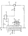
- The method and apparatus according to the present invention will now be described by way of example with reference to the accompanying drawing which is a schematic diagram illustrating a plant for separating argon and nitrogen from air.
- The drawing shows in a simplified form for the purposes of clarity of illustration an air separation plant adapted to produce gaseous argon and gaseous nitrogen products. A single distillation column 2 operating at a pressure of three atmospheres absolute has an inlet 4 compressed for air that has been purified (the purification including removal of water vapour, carbon dioxide and any hydrocarbons present in the air taken from the atmosphere) and at least partially liquefied by conventional means. The column 2 has a
condenser 8 towards its top and areboiler 10 towards its bottom. A plurality of liquid-vapour contact trays 9 are arranged intermediate thecondenser 8 and thereboiler 10 whereby liquid from the condenser is caused to flow down the column in mass exchange with vapour formed by thereboiler 10. In operation, air is separated into a nitrogen-rich vapour fraction that collects at the top of the column 2 and a oxygen-rich liquid fraction that collects at the bottom of the column 2. Nitrogen vapour is condensed by thecondenser 8 and liquid oxygen is vaporised by thereboiler 10. The necessary cooling for thecondenser 8 and heating for thereboiler 10 is provided by a conventional heat pump cycle (not shown). - The distillation system illustrated in the drawing additionally includes an
auxiliary column 12 provided with acondenser 14 and typically areboiler 16 with liquid-vapour contact trays 17 disposed therebetween whereby vapour whose concentration of argon is greater than that in the incdming air for separation withdrawn from the column 2 throughconduit 18 is separated into an oxygen-rich liquid that is returned viaconduit 20 to the column, 2 and an argon-rich vapour fraction that is taken as product from thecolumn 12 through theoutlet 22 above the uppermost tray thereof. - Liquid oxygen is withdrawn from the bottom of the column 2 at a temperature of approximately 102K through a
conduit 22 and is passed into achamber 26 where it is mixed with a first portion of a gaseous nitrogen stream at a temperature of 88K withdrawn from the top of the column 2 and passed through aconduit 24 into thechamber 26. Mixing is typically effected by bubbling the nitrogen vapour through the liquid oxygen in thechamber 26 and thechamber 26 is in effect a phase separator operated in reverse. The resulting mixture is withdrawn as a vapour-liquid mixture at a temperature of about 91K and a pressure of about 3 atmospheres from thechamber 26 and expanded throughexpansion valve 30 into one pass of aheat exchanger 32 at a pressure of about 1.5 atmospheres and a temperature of about 85.5K where it is employed to condense a second portion of the stream of vaporous nitrogen taken from the top of the column 2 and passed into theheat exchanger 32 via aconduit 34. The resulting liquid nitrogen condensate passes from theheat exchanger 32 throughconduit 36 into the top of the chamber 2 where it augments the reflux provided by thecondenser 8. After passage through theheat exchanger 32 the mixed oxygen-nitrogen stream is typically employed to provide cooling for the incoming air so as to assist in its liquefaction prior to its introduction into the column 2. - A third portion of the stream of vaporous nitrogen taken from the top of the column 2 is typically passed to an
outlet 38 from which it is taken from the plant as product nitrogen. - Cooling for the
condenser 14 of theauxiliary column 12 and heating for thereboiler 16 of the column may for example be provided by a conventional heat pump circuit which is not shown for purposes of clarity of illustration. - The mixing of the oxygen stream with the nitrogen stream in the
chamber 26 produces a net reduction in the temperature and this refrigeration effect by being employed to produce liquid nitrogen reflux for the column 2 reduces the heat pumping duty that the heat pumping circuit for the column 2 needs to perform. Accordingly, the overall separation efficiency of the argon is increased without there being any loss of argon yield. - If desired, the temperature of one or both of the first nitrogen- rich vapour stream and the oxygen-rich liquid stream that are mixed in the
chamber 26 may be adjusted by heat exchange upstream of thechamber 26. The mixture produced in thechamber 26 may if desired be sub-cooled upstream of theexpansion valve 30. - An oxygen product may if desired be taken from the oxygen-rich liquid stream.
Claims (13)
Applications Claiming Priority (2)
| Application Number | Priority Date | Filing Date | Title |
|---|---|---|---|
| GB8512563 | 1985-05-17 | ||
| GB858512563A GB8512563D0 (en) | 1985-05-17 | 1985-05-17 | Air separation method |
Publications (3)
| Publication Number | Publication Date |
|---|---|
| EP0202843A2 true EP0202843A2 (en) | 1986-11-26 |
| EP0202843A3 EP0202843A3 (en) | 1987-11-19 |
| EP0202843B1 EP0202843B1 (en) | 1990-07-18 |
Family
ID=10579314
Family Applications (1)
| Application Number | Title | Priority Date | Filing Date |
|---|---|---|---|
| EP86303609A Expired - Lifetime EP0202843B1 (en) | 1985-05-17 | 1986-05-12 | Air separation method and apparatus |
Country Status (6)
| Country | Link |
|---|---|
| US (1) | US4723975A (en) |
| EP (1) | EP0202843B1 (en) |
| JP (1) | JPH0792325B2 (en) |
| DE (1) | DE3672693D1 (en) |
| GB (2) | GB8512563D0 (en) |
| ZA (1) | ZA863538B (en) |
Cited By (2)
| Publication number | Priority date | Publication date | Assignee | Title |
|---|---|---|---|---|
| EP0269343A2 (en) * | 1986-11-24 | 1988-06-01 | The BOC Group plc | Air separation |
| EP0269342A2 (en) * | 1986-11-24 | 1988-06-01 | The BOC Group plc | Air separation |
Families Citing this family (2)
| Publication number | Priority date | Publication date | Assignee | Title |
|---|---|---|---|---|
| US5238670A (en) * | 1990-04-20 | 1993-08-24 | L'air Liquide, Societe Anonyme Pour L'etude Et L'exploitation Des Procedes Georges Claude | Process for preparing ultra-pure nitrogen |
| JP6440232B1 (en) * | 2018-03-20 | 2018-12-19 | レール・リキード−ソシエテ・アノニム・プール・レテュード・エ・レクスプロワタシオン・デ・プロセデ・ジョルジュ・クロード | Product nitrogen gas and product argon production method and production apparatus thereof |
Citations (3)
| Publication number | Priority date | Publication date | Assignee | Title |
|---|---|---|---|---|
| US2667764A (en) * | 1950-01-18 | 1954-02-02 | Hudson Engineering Corp | Refrigeration method, system, and apparatus |
| US4022030A (en) * | 1971-02-01 | 1977-05-10 | L'air Liquide, Societe Anonyme Pour L'etude Et L'exploitation Des Procedes Georges Claude | Thermal cycle for the compression of a fluid by the expansion of another fluid |
| EP0136926A1 (en) * | 1983-08-05 | 1985-04-10 | L'air Liquide, Societe Anonyme Pour L'etude Et L'exploitation Des Procedes Georges Claude | Process and apparatus for air distillation in a double column |
Family Cites Families (11)
| Publication number | Priority date | Publication date | Assignee | Title |
|---|---|---|---|---|
| US3127260A (en) * | 1964-03-31 | Separation of air into nitrogen | ||
| US3760596A (en) * | 1968-10-23 | 1973-09-25 | M Lemberg | Method of liberation of pure nitrogen and oxygen from air |
| DE1907525A1 (en) * | 1969-02-14 | 1970-08-20 | Vnii Kriogennogo Masinostrojen | Process for separating nitrogen and oxygen from the air |
| DE1922956B1 (en) * | 1969-05-06 | 1970-11-26 | Hoechst Ag | Process for the production of argon-free oxygen by the rectification of air |
| DE2135235A1 (en) * | 1971-07-14 | 1973-08-16 | Balabaew | PROCESS FOR AIR SEPARATION WITH EXTRACTION OF OXYGEN AND ARGON |
| US3756053A (en) * | 1972-05-01 | 1973-09-04 | Teledyne Inc | Method for bending tubes |
| US4137056A (en) * | 1974-04-26 | 1979-01-30 | Golovko Georgy A | Process for low-temperature separation of air |
| JPS5599571A (en) * | 1979-01-24 | 1980-07-29 | Hitachi Ltd | Method and device for picking up argon |
| JPS56124879A (en) * | 1980-02-26 | 1981-09-30 | Kobe Steel Ltd | Air liquefying and separating method and apparatus |
| JPS59150286A (en) * | 1983-02-15 | 1984-08-28 | 日本酸素株式会社 | Manufacture of argon |
| US4578095A (en) * | 1984-08-20 | 1986-03-25 | Erickson Donald C | Low energy high purity oxygen plus argon |
-
1985
- 1985-05-17 GB GB858512563A patent/GB8512563D0/en active Pending
-
1986
- 1986-05-12 DE DE8686303609T patent/DE3672693D1/en not_active Expired - Fee Related
- 1986-05-12 US US06/861,951 patent/US4723975A/en not_active Expired - Fee Related
- 1986-05-12 GB GB8611537A patent/GB2174917B/en not_active Expired
- 1986-05-12 EP EP86303609A patent/EP0202843B1/en not_active Expired - Lifetime
- 1986-05-13 ZA ZA863538A patent/ZA863538B/en unknown
- 1986-05-17 JP JP61113415A patent/JPH0792325B2/en not_active Expired - Lifetime
Patent Citations (3)
| Publication number | Priority date | Publication date | Assignee | Title |
|---|---|---|---|---|
| US2667764A (en) * | 1950-01-18 | 1954-02-02 | Hudson Engineering Corp | Refrigeration method, system, and apparatus |
| US4022030A (en) * | 1971-02-01 | 1977-05-10 | L'air Liquide, Societe Anonyme Pour L'etude Et L'exploitation Des Procedes Georges Claude | Thermal cycle for the compression of a fluid by the expansion of another fluid |
| EP0136926A1 (en) * | 1983-08-05 | 1985-04-10 | L'air Liquide, Societe Anonyme Pour L'etude Et L'exploitation Des Procedes Georges Claude | Process and apparatus for air distillation in a double column |
Cited By (4)
| Publication number | Priority date | Publication date | Assignee | Title |
|---|---|---|---|---|
| EP0269343A2 (en) * | 1986-11-24 | 1988-06-01 | The BOC Group plc | Air separation |
| EP0269342A2 (en) * | 1986-11-24 | 1988-06-01 | The BOC Group plc | Air separation |
| EP0269342A3 (en) * | 1986-11-24 | 1989-03-01 | The Boc Group Plc | Air separation |
| EP0269343A3 (en) * | 1986-11-24 | 1989-03-01 | The Boc Group Plc | Air separation |
Also Published As
| Publication number | Publication date |
|---|---|
| JPS61289284A (en) | 1986-12-19 |
| JPH0792325B2 (en) | 1995-10-09 |
| EP0202843A3 (en) | 1987-11-19 |
| GB8512563D0 (en) | 1985-06-19 |
| GB2174917A (en) | 1986-11-19 |
| GB2174917B (en) | 1989-07-05 |
| US4723975A (en) | 1988-02-09 |
| ZA863538B (en) | 1986-12-30 |
| DE3672693D1 (en) | 1990-08-23 |
| EP0202843B1 (en) | 1990-07-18 |
| GB8611537D0 (en) | 1986-06-18 |
Similar Documents
| Publication | Publication Date | Title |
|---|---|---|
| EP0633438B1 (en) | Air separation | |
| EP0173168B1 (en) | Process to produce ultrahigh purity oxygen | |
| EP0674144B1 (en) | Cryogenic rectification system for producing elevated pressure nitrogen | |
| US5228296A (en) | Cryogenic rectification system with argon heat pump | |
| US5533339A (en) | Air separation | |
| EP0684438B1 (en) | Air separation | |
| EP0687876B1 (en) | Air separation | |
| US5485729A (en) | Air separation | |
| EP0971188A1 (en) | Cryogenic rectification system with modular cold boxes | |
| US5657644A (en) | Air separation | |
| US5893276A (en) | Air separation | |
| US6279345B1 (en) | Cryogenic air separation system with split kettle recycle | |
| EP0752565B1 (en) | Production of Argon | |
| US5660059A (en) | Air separation | |
| US5144808A (en) | Cryogenic air separation process and apparatus | |
| EP0721094A2 (en) | Air separation | |
| EP0660058B1 (en) | Air separation | |
| US5092132A (en) | Separation of air: improved heylandt cycle | |
| JPH08247647A (en) | Separation of gas mixture | |
| EP0418139A1 (en) | Cryogenic air separation process and apparatus | |
| US5689975A (en) | Air separation | |
| EP0202843B1 (en) | Air separation method and apparatus | |
| US5809802A (en) | Air seperation | |
| EP0833118A2 (en) | Air separation | |
| US6170291B1 (en) | Separation of air |
Legal Events
| Date | Code | Title | Description |
|---|---|---|---|
| PUAI | Public reference made under article 153(3) epc to a published international application that has entered the european phase |
Free format text: ORIGINAL CODE: 0009012 |
|
| AK | Designated contracting states |
Kind code of ref document: A2 Designated state(s): BE DE FR IT NL SE |
|
| PUAL | Search report despatched |
Free format text: ORIGINAL CODE: 0009013 |
|
| AK | Designated contracting states |
Kind code of ref document: A3 Designated state(s): BE DE FR IT NL SE |
|
| 17P | Request for examination filed |
Effective date: 19880511 |
|
| 17Q | First examination report despatched |
Effective date: 19890118 |
|
| GRAA | (expected) grant |
Free format text: ORIGINAL CODE: 0009210 |
|
| AK | Designated contracting states |
Kind code of ref document: B1 Designated state(s): BE DE FR IT NL SE |
|
| PG25 | Lapsed in a contracting state [announced via postgrant information from national office to epo] |
Ref country code: IT Free format text: LAPSE BECAUSE OF FAILURE TO SUBMIT A TRANSLATION OF THE DESCRIPTION OR TO PAY THE FEE WITHIN THE PRE;WARNING: LAPSES OF ITALIAN PATENTS WITH EFFECTIVE DATE BEFORE 2007 MAY HAVE OCCURRED AT ANY TIME BEFORE 2007. THE CORRECT EFFECTIVE DATE MAY BE DIFFERENT FROM THE ONE RECORDED.SCRIBED TIME-LIMIT Effective date: 19900718 Ref country code: NL Effective date: 19900718 Ref country code: SE Effective date: 19900718 |
|
| ET | Fr: translation filed | ||
| REF | Corresponds to: |
Ref document number: 3672693 Country of ref document: DE Date of ref document: 19900823 |
|
| NLV1 | Nl: lapsed or annulled due to failure to fulfill the requirements of art. 29p and 29m of the patents act | ||
| PLBE | No opposition filed within time limit |
Free format text: ORIGINAL CODE: 0009261 |
|
| STAA | Information on the status of an ep patent application or granted ep patent |
Free format text: STATUS: NO OPPOSITION FILED WITHIN TIME LIMIT |
|
| 26N | No opposition filed | ||
| PGFP | Annual fee paid to national office [announced via postgrant information from national office to epo] |
Ref country code: FR Payment date: 19930409 Year of fee payment: 8 |
|
| PGFP | Annual fee paid to national office [announced via postgrant information from national office to epo] |
Ref country code: DE Payment date: 19930414 Year of fee payment: 8 |
|
| PGFP | Annual fee paid to national office [announced via postgrant information from national office to epo] |
Ref country code: BE Payment date: 19930422 Year of fee payment: 8 |
|
| PG25 | Lapsed in a contracting state [announced via postgrant information from national office to epo] |
Ref country code: BE Effective date: 19940531 |
|
| BERE | Be: lapsed |
Owner name: THE BOC GROUP P.L.C. Effective date: 19940531 |
|
| PG25 | Lapsed in a contracting state [announced via postgrant information from national office to epo] |
Ref country code: FR Effective date: 19950131 |
|
| PG25 | Lapsed in a contracting state [announced via postgrant information from national office to epo] |
Ref country code: DE Effective date: 19950201 |
|
| REG | Reference to a national code |
Ref country code: FR Ref legal event code: ST |